This is a simplified C++ class for handling microcontroller peripheral procedures.
TWENETmwf - Peripheral C++ Library
This is a simplified C++ class for handling microcontroller peripheral procedures.
Pre-defined objects are available (e.g., mwf::the_i2c0 for I2C0), and you access their functions through these objects. The pre-defined objects are smart pointers using std::unique_ptr<>, and their actual instances are created upon first initialization.
This library’s pre-defined objects include procedures for before and after sleep, allowing you to perform pre-sleep and wake-up processing in a single step.
About Peripheral Objects
Many peripherals have integrated initialization and other procedures. This library manages them as class objects, from their creation to their destruction.
All class objects are smart pointers using std::unique_ptr<>. Before an object is created, it’s a nullptr, so no access is possible (it will likely cause a hang-up from a null pointer access). Always check for nullptr before using an object.
if (the_adc) { // Check for nullptr first
the_adc->enable((1UL<<0) | (1UL<<1));
the_adc->start();
}
Pre-defined Peripheral Class Objects
Object Name
Description
the_adc
Use the Analog-to-Digital Converter (ADC)
the_gpio
Use General Purpose IO (GPIO) interrupts. (The class object is not used if you don’t need interrupts)
In principle, classes and functions are defined within the following namespaces:
mwf::
mwf::periph::
1 - mwf_common
mwf common definitions
Defines common definitions and base classes for peripheral classes.
mwf_common
Defines common definitions and base classes for peripheral classes.
Macros
BEGIN_CRITICAL, END_CRITICAL (Disable Interrupts)
#define BEGIN_CRITICAL { uint32_t __TWENET_regPrimask = DisableGlobalIRQ();
#define END_CRITICAL() EnableGlobalIRQ(__TWENET_regPrimask); }
// Example
externvolatileint critical_value;
voidsome_func() {
...
// The following is a critical section
BEGIN_CRITICAL
{
critical_value++;
}
END_CRITICAL();
}
These macros are used to set a disabled interrupt section. While they simply call DisableGlobalIRQ() and EnableGlobalIRQ(), they are defined as a macro similar to the do {...} while() construct to simplify the syntax, which can seem complex due to the need for a local variable.
In the example above, if critical_value is a value that might be changed by an interrupt handler, this procedure safely updates the value within the application’s processing.
This macro can only be used in C++ code.
Constants, Enumerations, etc.
enum class ID_SYSHAND
Defines IDs to identify peripheral class objects.
class sys_ev_handler
A high-level (abstract) class that defines an interface to standardize procedures for sleep and wake-up.
on_sleep()
Describes the peripheral’s procedures before sleep.
on_wakeup(bool init_2nd)
Describes the peripheral’s procedures to restore its pre-sleep state upon wake-up. This function is expected to be called twice.
When init_end is false, it is called at a very early stage after wake-up. It is primarily used for variable initialization, but no device re-initialization is performed here. The second time it is called, with true, it re-initializes devices and restores the pre-sleep state.
In TWENET, this is handled during the vAHI_OnWakeup_MW() call. The call order is as follows. For details, refer to twenet_main.c in TWENETmcu.
Call of the WarmMain() function (the first function called upon wake-up)
vAHI_OnWakeup_MW(FALSE)
The on_wakeup(false) of the mwf library object is called here
ToCoNet_vInit_Warm_Pre()
cbAppWarmStart(FALSE) (or init_warm() in mwx)
ToCoNet_vBoard_Init()
Initialization of the wireless microcontroller hardware (clock, etc.)
vAHI_OnWakeup_MW(TRUE)
The on_wakeup(true) of the mwf library object is called here
ToCoNet_vInit_Warm()
cbAppWarmStart(TRUE) (or setup() in mwx)
TWENET initialization
TWENET application loop
class sys_global_resource_handler<T>
A high-level class for managing initialization and destruction procedures when multiple instances of the same function are defined, such as I2C and PWM.
It is used when there are procedures that need to be performed only once upon initialization and procedures that need to be destroyed only after all instances have been used. (Even with these peripherals, this class may or may not be used depending on the implementation.)
The initialization and destruction procedures are performed based on a reference counter (passed from the constructor) that is updated whenever an object is created or destroyed.
sys_ev_handler is an abstract class, but this class uses CRTP.
init()
When the reference counter becomes 1 (i.e., when initialization is needed), T::global_init() is called.
This member function must be explicitly called from the peripheral class constructor.
deinit()
When the reference counter becomes 0, T::global_deinit() is called.
This member function must be explicitly called from the peripheral class destructor.
class sys_ev_manager
A collection class for managing peripheral class objects in a single place. However, it does not own the objects; it stores sys_ev_handler class pointers in a fixed array, using the ID specified by the ID_SYSHAND enumeration as an index.
Its main purpose is to perform on_sleep() and on_wake() procedures in a batch.
Since which peripheral class objects are created depends on the user’s program, calling if(the_pwm1) the_pwm1->on_sleep(); for every class object would be inefficient and link unnecessary code. Instead, it stores them as abstract objects of type sys_ev_handler and calls their virtual methods.
global_init_sysevmgr()
Creates the the_sys_ev_manager instance.
global_deinit_sysevmgr()
Destroys the the_sys_ev_manager instance.
reg_obj()
Registers a peripheral class object.
unreg_obj()
Deregisters a peripheral class object.
on_wakeup(bool init_2nd)
Executes on_wake() for all registered objects.
void on_sleep()
Executes on_sleep() for all registered objects.
Peripheral Class Definition Example
class timer_n_pwm :
public mwf::sys_ev_handler // Base class
, public mwf::sys_global_resource_handler<timer_n_pwm>// Base class (only if needed)
{
using global_hdr = mwf::sys_global_resource_handler<timer_n_pwm>;
// Define a shorthand because the name is long
staticuint32_t _global_init_ct;
// Reference counter for sys_global_resource_handler
public:
staticvoidglobal_init_pwm(uint8_t u8_pwm_id, ...) { ... }
staticvoidglobal_deinit_pwm_manager(uint8_t u8_pwm_id) { ... }
// Procedures for creating and destroying the actual instance of the_pwm?.
public:
// Constructor
timer_n_pwm(/* Constructor arguments */)
: mwf::sys_ev_handler(/*ID*/ ,static_cast<sys_ev_handler*>(this))
, mwf::sys_global_resource_handler<timer_n_pwm>(_global_init_ct)
{
global_hdr::init(); // Procedure for creating sys_global_resource_handler<>
}
// Destructor (defined as virtual because it inherits from an abstract class)
virtual ~timer_n_pwm()
{
global_hdr::deinit(); // Procedure for destroying sys_global_resource_handler<>
}
// Implementation of the sys_ev_handler class
virtual voidon_sleep() { ... } // Called before sleep
virtual voidon_wakeup() { ... } // Called after waking up from sleep
// Implementation of sys_global_resource_handler<>. Static member function.
staticvoidglobal_init(); // The very first initialization procedure
staticvoidglobal_deinit(); // The very last destruction procedure
};
...
uint32_t mwf::periph::timer_n_pwm::_global_init_ct; // The actual reference counter
The above is an excerpt from the definition of the PWM (mwf_periph_pwm.hpp) peripheral class. Most other classes do not use sys_global_resource_handler<>.
2 - mwf_periph_common - Peripheral common
mwf_periph_common - Peripheral common
Defines common peripheral definitions and pin operations.
mwf_periph_common - Peripheral common
include
#include "mwf_periph_common.hpp"
GPIO Operation Functions
These are static (inline) functions defined within struct pin that you can call.
If PORTOUT_INITSTATE_HIGH is specified for param, the pin will be set to a HIGH state when this function is called.
set_output()
void set_output(uint8_t pin, uint8_t value)
Changes the output state of pin. If value is PORT_HIGH (1), it sets the pin to HIGH; if PORT_LOW (0), it sets it to LOW.
get_input()
staticuint8_t get_input(uint8_t pin)
Reads the state of pin when it is in an input state. The return value is PORT_HIGH (1) for HIGH and PORT_LOW (0) for LOW.
get_input_bm()
staticuint32_tget_input_bm(uint32_t u32mask =0x3FFFFF)
// Example
uint32_t bm = get_input_bm((1ul<<0) | (1ul<<3));
if (bm & (1ul<<3)) { ... } // If PIO3 is HIGH
else { ... } // If PIO3 is LOW
Reads the input state of all pins as a bitmap.
The value of PIOn corresponds to the bit (1UL << n).
The values of pins not in an input state are undefined.
In the example, you specify a pin bitmap (u32mask) to get the state of input pins at once. For example, if you need the values for PIO0 and PIO3, you would specify (1ul << 0) | (1ul << 3).
The return value is also a bitmap of the input states. A HIGH level is represented by 1, and a LOW level by 0. For example, if PIO3 is HIGH, the 4th bit from the LSB will be 1.
set_output_bm()
staticvoidset_output_bm(uint32_t u32mask, uint8_t value)
// Example
set_output_bm((1ul<<0) | (1ul<<3), 0); // Sets PIO0 and 3 to LOW
Changes the output state for the pins corresponding to the bitmap specified by u32mask.
The value of PIOn corresponds to the bit (1UL << n).
If value is PORT_HIGH (1), it sets the output to HIGH; if PORT_LOW (0), it sets it to LOW.
In the example, you specify a pin bitmap (u32mask) to set the output state of multiple pins at once. For example, to set PIO0 and PIO3, you would specify (1ul << 0) | (1ul << 3). The value is 1 for a HIGH level and 0 for a LOW level.
PIN Operation Functions
These are static (inline) functions defined within struct pin that you can call.
This is for internal use. It sets pin pin as a GPIO output. If b_init_high is true, the initial output is a HIGH (Vcc) level; if false, it’s a LOW (GND) level.
The user program should use set_pin_as_output().
static void set_pullup()
staticvoid set_pullup(uint8_t pin, uint8_t mode)
This function sets IOCON_PIO_MODE(mode) for the PIO register of the specified pin pin. This bit controls the pull-up behavior.
This function uses __conf_digital() to set IOCON_PIO_FUNC(0x04) for the PIO register of the specified pin pin. This typically configures the pin for PWM output.
static void conf_adc_input()
staticvoid conf_adc_input(uint8_t pin)
For pins PIO14..19, this function makes the following settings to configure them for ADC:
This is for internal use. It manages the processes and necessary data for retaining the GPIO output state during sleep.
static bool __b_check_swdbg_port(uint8_t pin)
staticbool __b_check_swdbg_port(uint8_t pin)
This is for internal use. It determines whether a pin is used by the debugger during a debug session.
Behavior during Sleep
For pins whose GPIO output state has been set using set_pin_as_output(), the output state is maintained even during sleep. However, retention_on_sleep() and retention_on_wake() must be called appropriately. In TWENET, these functions are called during the pre-sleep and wake-from-sleep processes handled within the TWENETmcu and TWENETcmpt libraries.
3 - mwf_periph_adc - ADC
mwf_periph_adc - ADC
This is a peripheral object that summarizes the procedures for using the Analog-to-Digital Converter (ADC).
mwf_periph_adc - ADC
This is a peripheral object that summarizes the procedures for using the Analog-to-Digital Converter (ADC).
Code Example
The following example explicitly specifies the mwf:: namespace. To omit this, please write using namespace mwf;.
include
#include"mwf_periph_adc.hpp"
Initialization Procedure
// Create the the_adc class object
mwf::the_adc->global_init_adc_manager();

// Specify ADC input pins
mwf::pin::conf_adc_input(14);
mwf::pin::conf_adc_input(15);

// Initialization
mwf::the_adc->init();
int32_t i32temp;
int16_t i16volt;
// Executes the process of turning on the internal sensor, waiting for stabilization, and performing ADC measurement (one time only).
mwf::the_adc->temp_capture(i32temp, i16volt, 0);
// i32temp is the temperature in degrees Celsius multiplied by 128. i16volt is in millivolts.
Serial << format("%dC %dmV", i32temp >>7, i16volt);
class mwf::periph::adc
This section describes the main definitions for the the_adc class object.
These are the configuration definitions for the ADC channels.
struct config
structconfig {
uint8_t prescale;
};
This is a structure for setting configurations. It is passed as a parameter to init().
prescale: (Current version only supports DEFAULT_PRESCALE=6) A prescale value that determines the ADC conversion time. It sets (1ul << .prescale) to adc_config_t::clockDividerNumber defined in the fsl library and calls ::ADC_Init().
These functions create and destroy the the_adc class object.
set_pin_as_adc()
staticvoid set_pin_as_adc(uint8_t pin)
This function sets the specified pin number pin as an ADC input.
init()deinit()
voidinit(bool b_wait_init = true);
voiddeinit();
Initializes the ADC.
Setting b_wait_init to FALSE omits the ADC stabilization wait time (300ms). For details on handling the wait time, please refer to is_periph_enabled().
To initialize or re-initialize the ADC for internal temperature sensor acquisition, call init_for_temp_volt().
is_periph_enabled() returns true when the ADC has been initialized and the necessary waiting period has elapsed.
If the FRWT (Free Running Wake Timer) provided by the_wtimer is running, is_periph_enabled() will return false until the appropriate time has passed. You can get the tick count value at the time init() was called by calling get_init_freerun_tick().
If the FRWT is not running, the first call to is_periph_enabled() will incur a wait time of approximately 300 microseconds. To avoid this waiting process, you can call force_periph_enabled() immediately after calling init(). This forces the internal state to be treated as if the waiting period has already passed.
enable()
voidenable(uint32_t chmask);
This function sets the ADC to an operational state. chmask is a bitmask of the channels to be converted. For example, if you want to target ADC0, ADC1, and VCC, you would specify (1ul << CH_0) | (1ul << CH_1) | (1ul << CH_VCC).
start()stop()
voidstart(bool b_cont = false);
voidstop();
After calling enable(), you can start the ADC by calling start(). If b_cont is set to true, it will perform continuous conversion. Do not call start() if the ADC is already running.
To stop the conversion during continuous mode, call stop().
When the conversion is complete, a read of the_adc->available() will return true.
available()
boolavailable();
Returns true after the conversion is complete. After true is read, it returns false again.
is_started()
boolis_started();
Returns true if the ADC is currently running due to a call to start().
get_value()
uint16_tget_value(uint8_t ch);
Gets the 12-bit AD converted value for the channel specified by ch. Call this after the AD conversion is complete.
get_value_mv()
int16_tget_value_mv(uint8_t ch);
Gets the AD converted value in millivolts (mv) for the channel specified by ch. Call this after the AD conversion is complete.
Acquires the value of the on-chip temperature sensor. It also secondarily measures the supply voltage.
temp128th: Specifies the variable to store the temperature measurement result. The value is 128 times the value in degrees Celsius. The integer part can be calculated with temp128th >> 7, and the first decimal place with (10 * temp128th) >> 7.
volt_mv: Specifies the variable to store the voltage measurement result. The value is in millivolts [mV].
times_adc_scaler: Specifies a scaler value corresponding to the number of ADC repetitions. A value from 0 to 3 can be specified; 0 performs 1 AD conversion, 1 performs 2, 2 performs 4, and 3 performs 8, after which the values are averaged.
The return value is true on success and false on failure.
The following processes are performed implicitly:
If the temperature sensor is not ON, it is set to ON and the necessary waiting process is performed (see temp_power_on()).
The temperature sensor is turned OFF after execution.
It will fail if the ADC has not been initialized (init()).
If the device is not available after ADC initialization, it performs a waiting process (see is_periph_enabled()).
temp_get_capt_tick()
uint32_t temp_get_capt_tick()
This function returns the FRWT counter value from the last time the temperature was acquired.
temp_power_on(), temp_power_off()
void temp_power_on()
void temp_power_off()
These functions explicitly turn the temperature sensor ON/OFF.
If FRWT is enabled, you can shorten the waiting time by calling temp_power_on() in advance, as the function determines if the wait is complete based on the counter value.
This is for internal use. It calculates the temperature from the ADC measurement values.
get_ctrl0_adc_reg_context()
classctrl0_adc_reg;
ctrl0_adc_reg get_ctrl0_adc_reg_context(uint8_t mode, uint8_t tsamp)
// Example
if (auto rc = get_ctrl0_adc_reg_context(
0x0 , 0x14 )) {
; // This scope enables the (0x0, 0x14) setting. The original value is restored upon exiting the scope.
}
This is for internal use. It temporarily changes the ADC configuration parameters.
class mwf::periph::adc (sys_ev_handler)
on_sleep()
Performs the ADC stop process.
on_wakeup()
If the ADC was initialized before sleep, it performs the initialization procedure (init()). You must execute enable() and start() again.
Others
About Operation in Continuous Mode
The conversion cycle is determined by the hardware. In the current version, the prescaler value is fixed.
Usage with AHI and mwx
The mwf::the_adc is used internally by the AHI and mwx libraries, so caution is required when using it directly.
If you are using the AHI library and also mwf::the_adc, please avoid calling any ADC-related procedures directly (e.g., vAHI_ApConfigure(), vAHI_AdcEnable(), vAHI_AdcStartSample() in adc.c that comes with App_Tweline).
If you are using the mwx library and also mwf::the_adc, please do not perform operations on the Analogue class object (e.g., Analogue.setup()).
4 - mwf_periph_gint - GINT(GPIO)
mwf_periph_gint - GINT(GPIO)
I implement general-purpose I/O input/output settings and I/O interrupts using GINT.
mwf_periph_gint - GINT(GPIO)
Implements general-purpose I/O input/output settings and I/O interrupts using GINT.
In TWENET, initialization and interrupt handling are processed within the TWENET library (TWENETcmpt). User programs typically do not need to call these functions directly.
include
#include "mwf_periph_gint.hpp"
class mwf::periph::gint
This is the definition for the the_gint class object. The creation of a the_gint class object is required to use pins for interrupt operations (including sleep interrupts). For implementation details, please refer to the “GINT-based DIO Interrupt Implementation” section below.
This function specifies the pins to be targeted for interrupts.
The first parameter, u32mask_rising_edge, is a bitmap of the pins for which to detect a rising edge. The second parameter, u32mask_falling_edge, is a bitmap of the pins for which to detect a falling edge.
It is also possible to set both rising and falling edges.
gint_poll()
voidgint_poll();
Performs the same process as the interrupt handler.
Calling this function periodically from a 1ms system timer, for example, can sometimes alleviate the limitations described in the “GINT-based DIO Interrupt Implementation” section below (where a port state might change after being read in the interrupt handler and that change is not processed). In most cases, this process is not necessary.
These functions stop the interrupt operation for a pin after a state change is detected, which helps mitigate the effects of mechanical button bouncing, etc.
Specifically, when a pin’s state changes and an interrupt occurs, the pin that was determined to have changed within the interrupt handler is temporarily excluded from being an interrupt pin.
*Since the GINT interrupt mechanism cannot determine which pin caused the interrupt, the state of the pins is read immediately after the interrupt handler executes and compared with the previous state to detect a change.
If this option is set, you should call reactivate_in_pins() after a pin change has been detected and the pin state has stabilized.
reavtivate_int_pins()
voidreavtivate_int_pins();
This function resumes interrupts for pins that were temporarily stopped. Refer to the set_opt_stop_int_when_changed() option setting for details.
get_gint_context()
gint_context& get_gint_context();
This function accesses the internal structure. It is used to get the bitmaps of the configured rising and falling edge pins (.bm_rise and .bm_fall) and the wake-up cause pin during sleep (.bm_wake).
(Internal function, not to be used from user programs)
Configures the interrupt pins.
Determines and updates the pin state changes (if u32mask_rising_edge and u32mask_falling_edge are 0x80000000). If a state change occurs, it calls the callback function registered with init_int().
gint_handler()
staticvoidgint_handler();
(This is an internal function and should not be used from user programs)
(This is an internal function and should not be used from user programs)
This function extracts the pins that match the specified rising or falling edge conditions from the changed pins. The calculation uses the current bitmap state (bm_cur) and the changed pins (bm_changed).
class mwf::periph::gpio (sys_ev_handler)
on_sleep()
Stops the interrupt if GINT is active.
In TWENET, vAHI_DioOnSleep_MW() sets the interrupt-configured pins (configured via this library using set_int_pins_bm()) for wake-up from sleep. Note that you cannot specify rising or falling edges for wake-up from sleep.
on_wakeup()
If woken up by a GPIO interrupt, this function saves the pin information corresponding to the wake-up cause (PMC->WAKEIOSOUCE).
Also, if interrupt pins were specified before sleep, it re-initializes GINT so that the interrupt operation resumes.
GINT-based DIO Interrupt Implementation
Because the PINT functionality is limited to a maximum of 4 ports, a similar function has been implemented using GINT (Group INT). Since GINT is not an interrupt detection mechanism focused on specific pins like PINT, there are some limitations. As the TWENET library does not use PINT, if the limitations of the GINT implementation are problematic, you should consider implementing a PINT-based solution.
Limitations
Signals that change state again shortly after a state change, such as noise or short pulses, may lead to unexpected behavior (e.g., missed detections).
It is assumed that the same state will be maintained for a certain period after a state change.
Due to GINT’s constraints, a very short pulse can be detected by the GINT interrupt, but it is not possible to determine which pin has changed. For details, please refer to the “Implementation” section below.
If a state is maintained for about 10µs after an edge, the GINT edge can be re-configured, so it is expected to work in principle. However, for safety, a duration of about 30-50µs (equivalent to one interrupt handler execution time) is recommended as a guideline for the state to remain the same.
When detecting a falling edge from a GND state, and conversely, when detecting a rising edge from a VCC state, missed detections are more likely to occur in principle.
For signals containing chattering or noise, use the option to temporarily disable interrupts for the pin upon the first interrupt occurrence (vAHI_DioInterruptDisablePinsIntWhenChanged_MW(TRUE); or mwf::the_gpio->set_opt_stop_int_when_changed();). After waiting for a certain period for the pin state to stabilize, call vAHI_DioInterruptReavtivate_MW(); or mwf::the_gpio->reavtivate_int_pins();.
Although not necessary in most cases, calling the_gpio->gint_poll() periodically (e.g., from a 1ms system tick) can increase interrupt overhead but may mitigate the effect of missed detections.
Note: The values mentioned are based on a CPU operating at 32MHz.
Note: If you wish to use the semiconductor’s functions directly, please do so without initializing this library and use GINT or PINT directly.
Implementation
GINT’s original purpose is to treat multiple pins as a group and generate an interrupt when there is a change in the group as a whole, not to be aware of the state of individual pins.
It is implemented as follows:
The current pin state is read, and the GINT detection edge is set (falling for HIGH, rising for LOW) to enable the interrupt.
A GINT interrupt occurs (a change on one of the pins triggers the interrupt handler).
The state of each pin is read to detect which pins have changed.
The GINT detection edge setting is reconfigured to match the newly read pin states.
The application is notified (via a callback) of the pins that have changed.
Note: The interrupt handler will be called again immediately afterward.
Note: The values and numbers shown are based on a library code under development, with two target pins for detection and a microcontroller operating at 32MHz.
When two pins go to a LOW level at the same time
The interrupt handler is called 1.5µs after the interrupt occurs. The pre-interrupt processing (reading pins and reconfiguring the detection edge) takes up to 6.6µs. After that, the application is notified (via the interrupt callback), which takes until 22µs after the interrupt occurred.
The interrupt occurs one more time (this is thought to be the behavior of the GINT hardware). In the second interrupt, no state change is usually detected, but it may suppress exceptional missed detections.
Horizontal axis: (10µs/DIV)
Pink: From the start of the interrupt handler until the GINT detection edge is reconfigured (1V/div)
Cyan/Yellow: Input signal (2V/div)
If another pin changes during the interrupt handler, example 1
In this example, another pin (cyan) changed during the first part of the interrupt handler, so it was processed consistently within the first handler. The behavior is the same as the simultaneous change mentioned above. The changes of both the yellow and cyan pins are communicated to the application in the first interrupt.
Horizontal axis: (10µs/DIV)
Pink: From the start of the interrupt handler until the GINT detection edge is reconfigured (2V/div)
Blue: From the start to the end of the interrupt handler (2V/div)
Cyan/Yellow: Input signal (5V/div)
If another pin changes during the interrupt handler, example 2
In this example, another pin (cyan) changes during the interrupt handler, but since the change occurs after the detection edge has been reconfigured, an interrupt occurs immediately afterward. A third handler is executed after the second handler finishes. The change of the yellow pin is communicated to the application in the first interrupt, and the change of the cyan pin is communicated in the second interrupt.
Horizontal axis: (10µs/DIV)
Pink: From the start of the interrupt handler until the GINT detection edge is reconfigured (2V/div)
Blue: From the start to the end of the interrupt handler (2V/div)
Cyan/Yellow: Input signal (5V/div)
5 - mwf_periph_i2c - I2C
mwf_periph_i2c - I2C
This is a peripheral object that summarizes the procedures for using the I2C bus.
mwf_periph_i2c - I2C
This is a peripheral object that summarizes the procedures for using the I2C bus.
Code Example
The example below explicitly specifies the mwf:: namespace. If you want to omit it, write using namespace mwf;.
Include
#include"mwf_periph_i2c.hpp"
Initialization
// create instance of the_i2c0.
if (!mwf::the_i2c0) {
mwf::i2c::global_init_i2c0_manager();
}
// I2C device init
mwf::the_i2c0->init();
// write 2bytes (e.g. kick sensor capturing)
constuint8_t cmd1[] = { 0x60, 0x9C };
if (!mwf::the_i2c0->write_blocking(0x70, cmd1)) return false;
// wait (e.g. wait sensor data conversion.)
CLOCK_uDelay(1000*30); // wait some for sensor data conversion.
// read 6 bytes (e.g. read the sensor data.)
uint8_t data[6];
mwf::the_i2c0->read_blocking(0x70, data);
Read (Blocking API)
// write 2bytes (e.g. kick sensor capturing)
constuint8_t cmd1[] = { 0x60, 0x9C };
if (!mwf::the_i2c0->write_blocking(0x70, cmd1)) return false;
// wait (e.g. wait sensor data conversion.)
CLOCK_uDelay(1000*30); // wait some for sensor data conversion.
// read 6 bytes (e.g. read the sensor data.)
uint8_t data[6];
mwf::the_i2c0->read_blocking(0x70, data);
In this example, a command to start data acquisition is sent to the sensor, and after waiting for the sensor’s operation time (the time required by the sensor), data acquisition is performed.
Reading (Non-blocking API)
// write 2bytes (e.g. kick sensor capturing)
constuint8_t cmd1[] = { 0x60, 0x9C };
if (!mwf::the_i2c0->write(0x70, cmd1)) return false;
while(!mwf::the_i2c0->available()); // waiting for completion of write operation.
// wait (e.g. wait sensor data conversion.)
CLOCK_uDelay(1000*30); // wait some for sensor data conversion.
// read 6 bytes (e.g. read the sensor data.)
uint8_t data[6];
mwf::the_i2c0->read(0x70, data);
while(!mwf::the_i2c0->available()); // waiting for completion of read operation.
These are the same write() and read() functions as the blocking API, but with the non-blocking API, they return immediately without waiting for the data transmission to complete. You must either wait a sufficient amount of time or wait for the_i2c0->available() to become true before performing subsequent operations (in the example above, polling is performed immediately after write()/read(), so there is no difference in usage from the blocking API).
class mwf::periph::i2c
Describes the procedures for using I2C.
*Note: In the current implementation, only the the_i2c0 class object, which uses I2C0, is available.
E_PIN_CONF
enumclassE_PIN_CONF:uint8_t {
NODEF =0, // Not specified
PRIMARY =1, // Primary assignment (PIO10/11)
ALT =2// Alternate assignment (PIO15/16)
};
// Type for assignments, comparisons, etc. between enum class and int types.
using wE_PIN_CONF = mwf::enum_wapper<E_PIN_CONF>;
This is an enumeration for specifying pin assignments.
These functions create and destroy the the_i2c0 class object.
During creation, you can specify the pin configuration with pin_conf as either E_PIN_CONF::PRIMARY (value 0, SCL=PIO10, SDA=PIO11) or E_PIN_CONF::ALT (value 1, SCL=PIO15, SDA=PIO16). The pin initialization is performed when init() is called.
(eE_PIN_CONF is a wrapper class for enum class E_PIN_CONF, with definitions for assignment and comparison with int types.)
Initializes the I2C bus and performs the termination procedure. During initialization, clock_freq is provided as a parameter; if it is 0, the default clock of 100kHz is selected; otherwise, clock_freq[Hz] is specified as the frequency.
If pin_conf is not specified (E_PIN_CONF::NODEF value 0), the pins specified in global_init_i2c0_manager() are used. If pin_conf is specified, the pins are initialized with that setting. Thereafter, if this parameter is omitted, the last specified pins will be used.
write_blocking() is a blocking function that waits for the write to complete. write() is a non-blocking function that returns immediately without waiting for the write to finish. When the write is complete, .available() will be true.
addr is the 7-bit I2C bus address, buf is the data to be written, and size is the number of bytes to write. If buf is a fixed-size array of size N, N bytes are written.
read_blocking() is a blocking function that waits for the read to complete. read() is a non-blocking function that returns immediately without waiting for the read to finish. When the read is complete, .available() will be true.
addr is the 7-bit I2C bus address, buf is the data storage buffer, and size is the number of bytes to read. If buf is a fixed-size array of size N, N bytes are read.
This function performs non-blocking read/write operations. op specifies whether to read or write, addr is the I2C bus address, buf is the buffer for reading or writing, and size is the number of bytes to read or write.
These functions are adjusted for the mwx library to perform blocking read/write procedures. Call _start_blocking(), _transfer_blocking() as many times as needed, and then _stop_blocking(). The sendStop parameter in _transfer_blocking() can be set to true on the last transfer to appropriately send a STOP signal.
available()
boolavailable();
This function determines if a transfer has finished when using the non-blocking API. It returns true when the transfer is complete.
is_success()
boolis_success();
When using the non-blocking API, this function returns whether the last transfer was successful. A return value of true indicates that the transfer was successful.
class mwf::periph::i2c (sys_ev_handler)
on_sleep()
As a procedure before sleep, it terminates the use of the I2C device.
on_wakeup()
If the device was initialized (init() call) before sleep, init() is called again to re-initialize it.
6 - mwf_periph_ntag - NTAG
mwf_periph_ntag - NTAG
This describes the procedures for using the NTAG I2C controller (equivalent to NT3H2211) built into the JN5189.
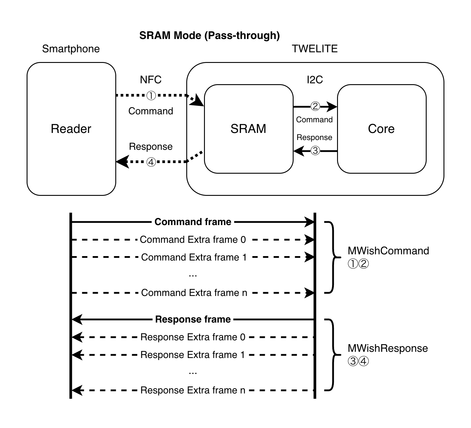
In addition to using it as a simple EEPROM, it can communicate with NFC readers. Communication modes include the standard EEPROM mode, which behaves as an NFC Forum Type 2 Tag using EEPROM, and an extended SRAM mode that exchanges commands and responses using a pass-through proprietary protocol.
The controller is connected via I2C, but it does not use mwf::periph::i2c. It uses a dedicated API and the I2C2 port.
EEPROM Usage
The JN5189 does not have a standalone EEPROM. To use EEPROM, use the EEPROM of the NTAG I2C controller.
This procedure allows reading and writing to a 1KB area (NT3H2211 I2C block addresses 64-127).
EEPROM Code Example
#include"mwf_periph_ntag.hpp"voidfunc() {
// create the_ntag class object.
if (!mwf::the_ntag) {
mwf::ntag::global_init_ntag_manager();
}
// initialize
mwf::the_ntag->init();
// write 128bytes
uint8_t xfer1[128];
for (unsigned i =0; i <128; i++) xfer1[i] = i;
mwf::the_ntag->write_user_area(0x00, xfer1);
// read 128bytes
uint8_t xfer2[128];
mwf::the_ntag->read_user_area(0x00, xfer2);
}
addr specifies the starting address from 0 to 1023. p or buf is the destination buffer for the data to be read. len or N is the number of data bytes.
NFC Usage
NFC Standard EEPROM Mode
In NFC standard EEPROM mode, NDEF messages can be written to or read from the EEPROM area by the device or a reader. While compatible with common NFC tags, transfer speed is similarly low, and bidirectional communication cannot be performed in a single session. Can be used with general-purpose apps such as NFC Tools ( Android / iOS ).
EEPROM Mode Operation
Below is an act sample that reads and writes NDEF URI records and Text records as a general NFC Forum Type 2 Tag.
#include<TWELITE>#include"mwf_periph_ntag.hpp"/*** the setup procedure (called on boot) */voidsetup() {
Serial <<"--- NFC Tag Text Example ---"<< crlf;
}
/*** the begin procedure (called after boot) */voidbegin() {
mwf::the_ntag->disable_pthru_mode(); // enabled by default
mwf::the_ntag->write_uri("twelite.net");
Serial <<"Set an URL as default. Can be overwritten with text via UART or NFC."<< crlf;
}
/*** the loop procedure (called every event) */voidloop() {
// NFC output text buffer
staticchar output_text[128];
staticchar* output_text_ptr =&output_text[0];
// Write serial input to NFC output
if (Serial.available()) {
char c;
Serial >> c;
Serial << c; // echo back
*(output_text_ptr++) = c;
if (c =='\n') {
*output_text_ptr ='\0';
mwf::the_ntag->write_text(output_text);
Serial << format("Set: %s", output_text) << crlf;
output_text_ptr =&output_text[0];
}
}
// Read NFC input if available
if (mwf::the_ntag->available()) {
char type;
mwf::the_ntag->read_ndef_record_type(&type);
if (type =='T') { // Text record
char input_text[128];
char input_lang[3];
mwf::the_ntag->read_text(input_text, input_lang);
Serial << format("Read: %s", input_text) << crlf;
}
}
}
Since TWENET enables extended SRAM mode during initialization, disable it inside begin()
In NFC extended SRAM mode, the device responds to commands sent by a reader. Commands and responses consist of one or more frames. The SRAM has a 64-byte area used for per-frame transfers. Transfer speed is fast, and data can be returned in a single session.
SRAM Mode Operation
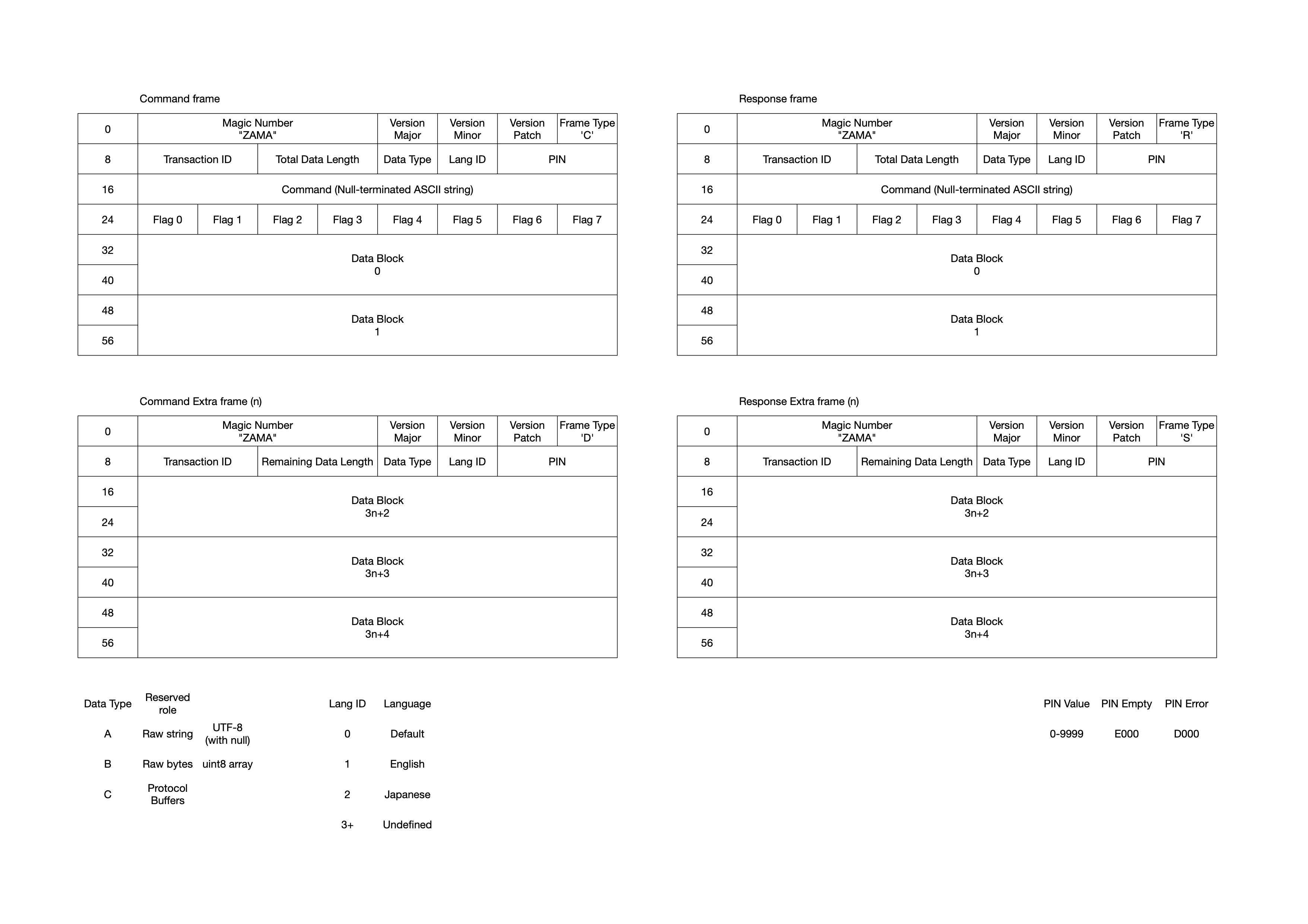
The TWELITE application exchanges frames in the MWish (Mono Wireless Interactive Shell) format defined as follows.
MWish Frame
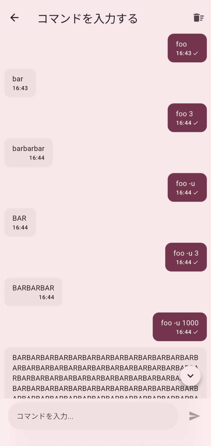
Below is an act sample that responds to command input from the TWELITE app ( Android / iOS ).
Here, a command foo that returns text is implemented as follows.
Running in the TWELITE App
foo -> bar
Returns bar in response to foo
foo 3 -> barbarbar
Repeats bar the number of times specified as an argument. Large transfers such as foo 1000 can be tested
foo -u -> BAR
The -u option (flag) returns uppercase BAR
foo -u 3 -> BARBARBAR
The -u option and argument can be applied simultaneously
#include<TWELITE>#include"mwf_periph_ntag.hpp"usingnamespace mwf::periph;
boolhandle_commands(const ntag::MWishCommand*const c, ntag::MWishResponse*const r) {
Serial <<"Received user command "<< c->command_str
<< format(" with flag(s) \"%s\" and data \"%s\"", c->flags, c->data) << crlf;
// Command foo [-u] [times] implementation:
// "foo" -> "bar"
// "foo 3" -> "barbarbar"
// "foo -u" -> "BAR"
// "foo -u 3" -> "BARBARBAR"
if (c->is_command("foo") and c->get_data_type() == ntag::PTHRU_DATA_TYPE::RAW_STRING) {
int times = strtol(reinterpret_cast<char*>(c->data), nullptr, 10);
if (times <1 or times *3> ntag::MWishResponse::DATA_MAX_SIZE -1) { times =1; }
for (int i =0; i < times; i++) {
if (c->contains_flag('u')) {
r->printf("BAR");
} else {
r->printf("bar");
}
}
return true;
}
return false; // No such command
}
/*** the setup procedure (called on boot) */voidsetup() {
Serial <<"--- NFC App Command Example ---"<< crlf;
}
/*** the begin procedure (called after boot) */voidbegin() {
mwf::the_ntag->enable_pthru_mode(); // enabled by default
mwf::the_ntag->attach_pthru_command_handler(handle_commands);
Serial <<"Registered user command(s)."<< crlf;
}
/*** the loop procedure (called every event) */voidloop() {
// Update NFC pass-through process
mwf::the_ntag->update_pthru();
}
It may be helpful to erase the tag in advance using NFC Tools or similar apps.
Although extended SRAM mode is enabled during TWENET initialization, it is explicitly enabled inside begin()
RECEIVE_COMMAND Receiving the (first) frame of a command
RECEIVE_COMMAND_EX Receiving an extended frame of a command
SEND_RESPONSE Sending a response frame
enable_wakeup_source()
voidenable_wakeup_source();
Enables waking from sleep via NFC.
disable_wakeup_source()
voiddisable_wakeup_source();
Disables waking from sleep via NFC.
check_if_wokeup_via_nfc()
staticboolcheck_if_wokeup_via_nfc();
Returns true when woken from sleep via NFC.
attach_callback_fd_in()
voidattach_callback_fd_in(void (*callback)());
Registers a callback function called when a reader is detected.
attach_callback_fd_out()
voidattach_callback_fd_out(void (*callback)());
Registers a callback function called when a reader departs.
NFC Standard EEPROM Mode
To use standard EEPROM mode, call mwf::the_ntag->disable_pthru_mode() after TWENET initialization. TWENET enables extended SRAM mode during initialization. For acts, you can use begin() {}.
Registers a handler for processing responses to commands (use is_system = true for system-level handlers).
sys_ev_handler Related
on_sleep()
Performs the termination procedure before sleep.
on_wakeup()
If the device was initialized before sleep, it re-initializes it. If re-initialization is not required, call deinit() before sleeping.
7 - mwf_periph_pwm - PWM, Timer
mwf_periph_pwm - PWM, Timer
This is a peripheral object that summarizes the procedures for using PWM and timers.
mwf_periph_pwm - PWM, Timer
This is a peripheral object that summarizes the procedures for using PWM and timers.
The the_pwm[] class object is used for operations. Although the class object is defined as an array, you can use PWM0 (the_pwm[0]) to PWM9 (the_pwm[9]).
PWM10 is not supported by this library.
Code Example
The example below explicitly specifies the mwf:: namespace. If you want to omit it, write using namespace mwf;.
#include"mwf_periph_pwm.hpp"// in some func.
voidfunc() {
// create instance of PMW0.
if (!the_pwm[0]) { // The class object of PMW0 is the_pwm[0].
timer_n_pwm::global_init_pwm_manager(
0, // PWM0
timer_n_pwm::PIN::ALT,
// The timer_n_pwm::PIN::PRIMARY will assign smaller PIO number PIO0 from PWM0,
// or conversely, timer_n_pwm::PIN::::ALT assigns PIO12.
true // set true to enable PWM output.
);
}
// set `x' as an alias of the_pwm[0].
auto& x = the_pwm[0];
// Init the device
//x->init(); // not necessary, the constructor will call init() implicitly.
// if needs INT, set true. (default: false)
x->set_int_enabled(true);
// set prescale
x->set_prescale(6); // 0:32MHz 1:16Mhz 2:8Mhz ...
// set polarity: if false, set HIGH while active state. (default: false)
x->set_invert(false);
// set cycle
// note: 500Hz Duty 10% (Hi 0.2ms, Low 1.8ms)
x->set_cycle(
100// conut for an active state (HIGH)
, 999// count for a period (+1)
);
// start PWM out
x->restart();
}
// INT handler (call set_int_enabled() before restart())
// note: if TWENETcmpt library is not linked, the IRQ handlers for PWM1..9 shall be defined.
extern"C"void PWM0_IRQHandler(void) {
... // some procedures.
PWM_ClearStatusFlags(PWM, kPWM_Pwm0);
}
To construct the the_pwm[] class object, you specify the PWM number and the corresponding pin.
The PWM number is specified as u8_pwm_id. Each PWM has two available pins (PWM5 only has PIO16). In this API, you can either specify the pin number directly as u8_pin_number or specify the lower pin number (timer_n_pwm::PIN::PRIMARY) or the other pin number (timer_n_pwm::PIN::ALT) from the available pins.
The behavior is undefined if you specify a conflicting number.
Changes the output state of the pin. If b_enable is true, the output is enabled, and the hardware pin settings are also changed. If it is false, the pin is set to the default setting (conf::pin::conf_default()).
This function can be called while PWM is active.
If the output is already set by a parameter in global_init_pwm_manager(), there is no need to call this function again.
These functions set the prescale for PWM control, which determines the PWM control frequency.
These functions can be called while PWM is active.
If set_prescale(u8_prescale) is specified, the control frequency is determined as follows: 0: 32MHz, 1: 16MHz, 2: 8MHz, …, 9: 62500Hz, 10: 31250Hz. Values 11 and above are undefined (assert in debug mode).
If set_divisor(u16_div) is specified, the control frequency is (32MHz / u16_div). The valid range is 1 to 1024, and the behavior is undefined if a value outside this range is specified.
The PWM period and duty cycle are determined by the parameters of set_cycle().
For example, if set_prescale(2) is specified, the control frequency is fb=8MHz. With this setting, if set_cycle(2, 10) is specified, the PWM period is fb/10 = 800kHz, and the pulse width is 2/fb = 2/8000000 = 250ns.
set_cycle()
voidset_cycle(uint16_t ct_comp, uint16_t ct_period);
uint16_tget_period_val(); // get total period count
uint16_tget_comp_val(); // get active region count
This function specifies the count values that determine one PWM cycle and the active period within it. The pin value changes during the active period, and an interrupt is generated at its end.
ct_comp is the count for the active period, and ct_period is the total count for one cycle. For example, if ct_comp is 100 and ct_period is 1000, the PWM period will be 1000 counts at the PWM control frequency. With set_invert(false), the behavior will be HIGH for 100 counts and LOW for the remaining 900 counts.
This function can be called while PWM is active.
ct_comp is valid from 0 to ct_period - 1. The upper limit for the active period ratio is (ct_period - 1) / ct_period, and it cannot be set to 100%. set_duty() takes a 100% setting into consideration.
The count value for one cycle, ct_period, is set as ct_period - 1 in the hardware register. Please be careful not to specify the hardware register value directly in this function.
You must have previously used set_cycle() to specify the count for one PWM cycle. If you omit this step, u16duty_max is set as the PWM cycle count.
The active period is set to a ratio of u16_duty/u16duty_max of the total cycle. For example, if set_duty(100) is specified, the active period is 10% of the cycle.
If u16duty is set to the same value as u16duty_max, the entire cycle becomes active, resulting in a HIGH level if the default non-inverted waveform output (set_invert(false)) is used. (Due to hardware constraints, the active period cannot be set to the entire cycle. Internally, the waveform output register is inverted, and the active period is set to 0.)
For this reason, if you call set_cycle() after setting the duty cycle to 100% with set_duty(), the waveform will be inverted. Please be careful not to mix their usage.
This function inverts the output waveform. When set to false (default), the active period is at a HIGH level. When set to true, it is at a LOW level.
start(), stop()
voidstart();
voidrestart();
voidstop();
These functions start, restart (with current settings), and stop the PWM output.
When stopped with stop(), the pin state is LOW if set_invert(false) (default) is set, and HIGH if set_invert(false) is set.
class mwf::periph::timer_n_pwm (sys_ev_handler)
sys_ev_handler is a procedure for before and after sleep.
on_sleep()
The PWM execution state is saved, and the pin state is returned to the default setting during sleep.
on_wakeup()
The state saved before sleep is restored.
class mwf::periph::timer_n_pwm (sys_global_resource_handler)
The sys_global_resource_handler<T> (where T is the timer_n_pwm class) is a procedure for performing necessary initialization and termination only once for multiple PWM class objects. It is used implicitly internally.
The constructor and on_wakeup() call sys_global_resource_handler<T>::init().
If it’s the first instance created, it calls T::global_init().
The destructor and on_sleep() call sys_global_resource_handler<T>::deinit().
If it’s the last instance to be destroyed, it calls T::global_deinit().
T::global_init()
Calls ::PWM_Init() to initialize the PWM.
T::global_deinit()
Calls ::PWM_DeInit() to terminate the use of the PWM.
Interrupts
When set_int_enabled(true) is set, an interrupt is generated at the end of the active period. The interrupt handler is provided by the system and is named PWMn_IRWHandler() (where n is the PWM channel).
              Interrupt
                 V                 Interrupt
                 V
Vcc    +----+                +----+
       |    |                |    |                t
GND----+    +----------------+    +-------------->
       <----> Active Period
       <--------------------> One PWM Cycle
The interrupt handler must be explicitly defined. The handler function that needs to be defined changes depending on whether the TWENETcmpt library is linked.
If TWENETcmpt is linked, only define the handler for the PWM channel you are using.
If TWENETcmpt is not linked, you must explicitly define interrupt handlers for all PWM channels from PWM0 to PWM9, even if you are not using an interrupt.
Interrupt Handler
When using TWENET, interrupts are converted into an interrupt function (cbToCoNet_u8HwInt()) and an event (cbToCoNet_vHwEvent()).
If you want to define your own interrupt handler, you must define PWNn_IRQHandler() separately. The following example shows a definition for PWM1. When you define your own, TWENET interrupts and events will not be generated.
// note: in c file, `extern "C"' should be removed.
extern"C"void PWM1_IRQHandler(void) {
PWM_ClearStatusFlags(PWM, kPWM_Pwm1);
}
8 - mwf_periph_rng - TRNG
mwf_periph_rng - TRNG
This is a peripheral object that summarizes the procedures for using the chip’s built-in random number generation hardware.
mwf_periph_rng - TRNG
This implements the_rng, a peripheral object that summarizes the procedures for using the chip’s built-in random number generation hardware.
With TWENET, this is used implicitly, so no initialization procedure is required in the user’s program.
Code example
if (!mwf::the_rng) {
    mwf::rng::global_init_rng_manager();
    mwf::the_rng->init();
}

uint32_t val = mwf::the_rng->random();
These functions create and destroy the the_rng class object. The class object is automatically initialized upon creation, and random values can then be obtained.
random()
uint32_t random()
Returns a random value.
class mwf::periph::rng (sys_ev_handler)
on_sleep()
Performs the TRNG stop procedure.
on_wakeup()
Performs the TRNG startup procedure.
9 - mwf_periph_spi - SPI
mwf_periph_spi - SPI
This is a class object for using the SPI bus.
mwf_periph_spi - SPI
This implements the_spi1, a class object for using the SPI bus.
SPI0 support is not included in the code.
Some definitions are included for non-blocking operations, but only blocking APIs are available in the current version.
Code Example
#include"mwf_periph_spi.hpp"voidfunc_spi_init() {
if (!mwf::the_spi1) {
mwf::spi::global_init_spi1_manager();
Serial << crlf <<"the_spi1 constructed.";
}
mwf::spi::config conf{};
conf.baud =4000000UL; // 4MHz
conf.bits =8; // 8bit
conf.dir = mwf::spi::E_SPI_DIR::MSB_FIRST;
conf.mode = mwf::spi::E_SPI_MODE::MODE_3_INV_RISE;
conf.pin_ssel[0] = mwf::spi::E_PIN_SSEL::SSEL0_PIO3;
conf.pin_ssel[1] = mwf::spi::E_PIN_SSEL::SSEL1_PIO16;
mwf::the_spi1->init(conf);
}
voidfunc_spi_transfer() {
uint8_t tx[16] = { 0xa5, 0x5a, 0x11, 0x88 }; // data to transmit
uint8_t rx[16]; // receive buffer
mwf::the_spi1->ssel_select(0);
mwf::the_spi1->transfer_blocking(tx, rx, 4); // four bytes transfer
CLOCK_uDelay(5); // wait 5us
mwf::the_spi1->transfer_blocking(tx, rx, 4); // four bytes transfer
mwf::the_spi1->ssel_deselect();
}
class mwf::periph::spi
struct config
The mwf::periph::spi::config structure is defined as follows:
structconfig {
// evaluated only in init()
E_PIN_MAIN pin_conf; // master pin configuration (so far not used)
E_PIN_SSEL pin_ssel[3]; // SSEL0..2 (assignment settings for slave select pins.
// At least pin_ssel[0] shall be configured.
// evaluated in conf(), reconf()
uint32_t baud; // SPI frequency (default 50Mhz)
E_SPI_DIR dir; // transfer LSB first
E_SPI_MODE mode; // SPI mode (clock polarity and detect edge)
uint8_t bits; // bit width (0:default=8, ...)
uint8_t ssel; // 0..3 or 0x80..0x80 (if MSB is set, assert/deassert SSEL automatically)
};
You set values in the structure and call init(). The structure’s settings are copied internally during the init() call, so you can discard the structure’s memory area afterward.
Here is an explanation of each member of the structure:
Signal Name
Description
pin_conf
Specifies the pin assignment (primary or alternate). If E_PIN_CONF::NODEF (=0) is selected, the setting from global_init_spi1_manager() is used.
pin_ssel[3]
Specifies the SELECT pins. Index 0 of the array specifies the pin for SPI SELECT 0 (SSEL0), index 1 for SSEL1, and index 2 for SSEL2. SSEL0 must always be specified, while SSEL1 and SSEL2 should be set to E_PIN_SSEL::SSEL_VOID=0. If you use two types of pins, specify SSEL0 and SSEL1; if you use three, store values in all of them. *Note: If you specify a software-controlled pin (e.g., E_PIN_SSEL::SSEL0_PIO3), all select pins will be software-controlled. With software control, the pins are set to a continuous HIGH level output and change to a LOW level when selected. TWENETcmpt (AHI library compatible) uses software control. *Note: With hardware control, the SELECT pin control follows the behavior of SPI_MasterTransferNonBlocking() in fsl_spi.c.
baud
Specifies the SPI clock frequency. It can be set up to 32MHz, but frequencies around 1MHz are often used for sensor devices.<br />(Behavior follows spi_master_config_t::bandRate_Bps in fsl_spi.h and SPI_MasterSetBaud() in fsl_spi.c)
mode
SPISEL is specified in init().
bits
This is the transfer unit. 8 is usually specified. It can be set from 1 to 16. If 9 bits or more are specified, the byte array for data transfer is read in 2-byte units, requiring twice the amount of data. The first byte represents 8 bits from the LSB, and the second byte represents the remaining bits. (Behavior follows SPI_MasterTransferBlocking() in fsl_spi.h)
ssel
This is the SPI SELECT. Specify 0 to 2.
enum class E_PIN_CONF
enumclassE_PIN_CONF:uint8_t {
NODEF =0, // Not specified
PRIMARY =1, // Primary assignment (PIO10/11)
ALT =2// Alternate assignment (PIO15/16)
};
// Type for assignments, comparisons, etc. between enum class and int types.
using wE_PIN_CONF = mwf::enum_wapper<E_PIN_CONF>;
This is an enumeration for specifying pin assignments.
enum class E_PIN_SSEL
enumclassE_PIN_SSEL:uint8_t {
SSEL_VOID =0, // Undefined
SSEL_PRIMARY, // Primary setting pin
SSEL_ALT, // Alternate setting pin
SSEL_SOFT =0x10,
SSEL0_PIO3, // SSEL0 is software-controlled, using PIO3
SSEL1_PIO16, // SSEL1 is software-controlled, using PIO16
SSEL2_PIO17, // SSEL2 is software-controlled, using PIO17
SSEL1_PIO4, // SSEL1 is software-controlled, using PIO4
SSEL2_PIO13, // SSEL2 is software-controlled, using PIO13
};
This enumeration determines the arrangement of the SPI SELECT pins. The corresponding value is stored in spi::config::pin_ssel[3].
Set pin_ssel[] according to the number of devices used.
For one device, set pin_ssel[0]. pin_ssel[1] and pin_ssel[2] should be SSEL_VOID.
For two devices, set pin_ssel[0] and pin_ssel[1]. pin_ssel[2] should be SSEL_VOID.
For three devices, set pin_ssel[0], pin_ssel[1], and pin_ssel[2].
To specify hardware control, use SSEL_PRIMARY or SSEL_ALT (and SSEL_VOID). If you mix them, it will result in software control.
enum class E_SPI_DIR
enumclassE_SPI_DIR {
MSB_FIRST =0,
LSB_FIRST
};
This specifies the bit order. MSB_FIRST is typically used.
This specifies the SPI transfer mode. It determines the clock’s detection edge and whether the H/L value at that time is 0 or 1. Set this according to the connected device’s datasheet.
These functions create and destroy the class object for using the SPI1 bus. During class object creation, you select the pin combination to use with pin_conf. You can specify E_PIN_MAIN::PRIMARY (value 0) or E_PIN_MAIN::ALT (value 1) for the pin configuration.
This function initializes the SPI bus. By providing the cnf parameter, you can set several configurations. If the parameter is omitted, it re-initializes with the previous settings.
Even if you are software-controlling the select pin in your user program, you must specify at least one. The specified pin will be configured as a GPIO output. By calling unset_ssel_auto(), the library will no longer control that pin.
reconf()
voidreconf();
This function re-applies the peripheral parameters. To access the internal settings, use spi::config& get_conf(). Pin settings (pin_ssel[]) are not reflected by this procedure.
set_data_width()
voidset_data_width(uint8_t bits);
This function changes the transfer data width. It is a lighter procedure than reconf().
Sets, unsets, and gets the automatic control flag for the select pin.
This is only effective when using software control.
When transfer_blocking() is called, the SELECT pin is automatically set to LOW. It is set back to HIGH upon completion.
ssel_select()
voidssel_select(uint8_t select);
This function specifies the select pin. select takes values of 0, 1, or 2, corresponding to SSEL0 through SSEL2.
With hardware or software control and the automatic control flag (set_ssel_auto()) enabled, pin control is performed when the transfer API is called.
With software control, regardless of the automatic control flag, the SELECT pin is set to LOW immediately after the ssel_select() call.
With hardware control, it calls reconf() to re-initialize. This process has a high time cost, so if you frequently switch between devices for transfers, please use software control.
ssel_deselect()
voidssel_deselect();
This function deselects the select pins.
With software control, all select pins are returned to a HIGH level.
With hardware control, it does nothing.
It does not change the pin specification from ssel_select().
Other
boolhas_init(); // Returns true if init() has been executed
spi::config& get_conf(); // Accesses internally stored configuration information
Pin Assignments
For E_PIN_CONF::PRIMARY
Signal
PIO Number
Description
SCK
0
Clock signal
MOSI
2
SPIMOSI. TWELITE side is output, external SPI device side is input.
MISO
5
SPIMISO. TWELITE side is input, external SPI device side is output.
Select Pins
pin_ssel
E_PIN_SSEL
PIO
Remarks
SSEL0pin_ssel[0]
SSEL_PRIMARY
3
SSEL_ALT
16
SSEL0_PIO3
3
Software-controlled
SSEL0_PIO16
16
Software-controlled
SSEL1pin_ssel[1]
SSEL_PRIMARY
4
SSEL_ALT
14
SSEL1_PIO4
4
Software-controlled
SSEL1_PIO14
14
Software-controlled
SSEL1_PIO16
16
Software-controlled (Cannot specify SSEL0_PIO16)
SSEL_VOID
Only use SSEL0 for selection
SSEL2pin_ssel[2]
SSEL_PRIMARY
13
SSEL2_PIO13
13
Software-controlled
SSEL2_PIO17
17
Software-controlled
SSEL_VOID
Only use SSEL0 and SSEL1 for selection
A maximum of three select pins can be set in order from SSEL0 to SSEL1 and SSEL2.
If any of the pin_ssel[] specifications are for software control, all select pins will be software-controlled by the library.
For E_PIN_CONF::ALT
Signal
PIO Number
Description
SCK
15
Clock signal
MOSI
17
SPIMOSI. TWELITE side is output, external SPI device side is input.
MISO
18
SPIMISO. TWELITE side is input, external SPI device side is output.
Select Pins
pin_ssel
E_PIN_SSEL
PIO
Remarks
SSEL0pin_ssel[0]
SSEL_PRIMARY
16
SSEL_ALT
3
SSEL0_PIO3
3
Software-controlled
SSEL0_PIO16
16
Software-controlled
SSEL1pin_ssel[1]
SSEL_PRIMARY
14
SSEL0 must be specified
SSEL_ALT
4
SSEL1_PIO4
4
Software-controlled
SSEL1_PIO14
14
Software-controlled
SSEL_VOID
Only use SSEL0 for selection
SSEL2pin_ssel[2]
SSEL_PRIMARY
13
SSEL_ALT
5
Note that this is also the PRG pin.
SSEL2_PIO5
5
Software-controlled. Note that this is also the PRG pin.
SSEL2_PIO13
13
Software-controlled
SSEL_VOID
Only use SSEL0 and SSEL1 for selection
A maximum of three select pins can be set in order from SSEL0 to SSEL1 and SSEL2.
If any of the pin_ssel[] specifications are for software control, all select pins will be software-controlled by the library.
class mwf::periph::spi (sys_ev_handler)
on_sleep()
As a procedure before sleep, the SPI is returned to an unused state. If it has been initialized by init(), this state is saved.
on_wakeup()
If it was in an initialized state before sleep, it is re-initialized so that the SPI bus can be used.
10 - mwf_periph_wtimer - WTIMER, FRWT
mwf_periph_wtimer - WTIMER, FRWT
This is a peripheral object that summarizes the procedures for using the wake-up timer.
mwf_periph_wtimer - WWDT, FRWT
This implements the_wtimer, a peripheral object that summarizes the procedures for using the wake-up timer.
With TWENET, this is used implicitly, so no initialization is required in the user’s program.
The wake-up timer counts down based on the 32768Hz crystal oscillator built into the module. For example, if the timer starts from 32768, the counter will reach 0 and an interrupt will occur after 1 second. It is typically used for waking up from sleep. Since the counter continues to count down even after waking up, you can calculate the elapsed time since waking up by reading the counter value.
There are two wake-up timer channels: channel 0 uses a 40-bit counter (used as a 32-bit counter in this library), and channel 1 uses a 28-bit counter.
The FRWT (Free Running Wake Timer) procedure, which uses the wake-up timer, is also included. By taking advantage of its ability to operate with low current consumption during sleep, one of the two wake-up timer channels can be kept running constantly, allowing it to be used as a counter for real-time. In TWENET, FRWT functions with a specific setting, which allows for efficient waiting for ADC initialization, etc., while FRWT is running.
TWENET uses channel 0 as the FRWT and channel 1 as the regular wake-up timer.
For dev, specify the device number of the wake-up timer to be used (WTIMER0_DEVICE or WTIMER1_DEVICE).
For u32ct, specify the initial count value.
If you specify a wake-up timer channel that is currently running as an FRWT, the function will do nothing.
read()
uint32_t read(uint8_t dev)
This function reads the count value of the wake-up timer.
For dev, specify the device number of the wake-up timer to be used (WTIMER0_DEVICE or WTIMER1_DEVICE).
The value of a wake-up timer channel that is currently running as an FRWT cannot be read.
is_running()
bool is_running(uint8_t dev)
This function determines whether the wake-up timer is currently running.
For dev, specify the device number of the wake-up timer to be used (WTIMER0_DEVICE or WTIMER1_DEVICE).
If you specify a wake-up timer channel that is currently running as an FRWT, it returns false.
set_interrupt()
void set_interrupt(uint8_t dev, bool b_enabled)
This function specifies whether the wake-up timer should generate an interrupt.
For dev, specify the device number of the wake-up timer to be used (WTIMER0_DEVICE or WTIMER1_DEVICE).
Setting b_enabled to true enables interrupts. If this is not specified, an interrupt will not occur even when waking up from sleep. Note that once true has been specified for a wake-up timer, you cannot disable the interrupt by specifying false.
If you specify a wake-up timer channel that is currently running as an FRWT, the function will do nothing.
get_fired_status_on_wakeup()
uint8_t get_fired_status_on_wakeup()
This function is called after waking up from sleep. If the wake-up cause was a wake-up timer, the corresponding bit (WTIMER0_DEVICE_MASK or WTIMER1_DEVICE_MASK) will be set.
class mwf::periph::wtimer (sys_ev_handler)
on_sleep()
There are no special procedures.
on_wakeup()
This function confirms the wake-up cause, saves the information internally, and clears the interrupt status. The timer also does not stop.
These functions start and stop the FRWT. The count value is incremented at 32768Hz, starting from 0 at the beginning.
For dev, specify the device number of the wake-up timer (WTIMER0_DEVICE or WTIMER1_DEVICE).
freerun_is_running()
bool freerun_is_running()
Returns true if the FRWT is running.
freerun_is_device()
bool freerun_is_device(uint8_t dev)
Returns true if the specified device is the one running as an FRWT.
For dev, specify the device number of the wake-up timer (WTIMER0_DEVICE or WTIMER1_DEVICE).
freerun_ct_get()
uint32_t freerun_ct_get()
Returns the FRWT’s count value. The FRWT’s count value is not the wake-up timer’s value itself, but is converted to an incrementing value from 0 (roughly a value with its sign inverted).
Count Value Calculation Functions
These functions convert the FRWT count value to milliseconds or calculate the difference between two count values.
This function converts the FRWT count value ct to milliseconds. If dec_part is specified, it sets the value of the 1/10th digit to a value from 0 to 9.
This function calculates the difference between two count values. It is essentially val_now - val_past, but it is calculated to account for cases where the counter returns to 0 after reaching its maximum value. Time differences up to half of the maximum counter value can be calculated, and if val_past is older, it returns a positive value.
freerun_ct_diff_msec()
int32_t freerun_ct_diff_msec(int32 vdiff)
This function converts the counter difference vdiff obtained from freerun_ct_diff() to milliseconds.
This function converts the counter difference vdiff obtained from freerun_ct_diff() or the counter difference calculated from val_past and val_now to microseconds.
Due to calculation, an int32_t overflow can occur (e.g., if the time difference exceeds approximately 2000 seconds).
11 - mwf_periph_wwdt - WWDT
mwf_periph_wwdt - WWDT
This is a peripheral object that summarizes the procedures for using the watchdog timer.
mwf_periph_wwdt - WWDT
the_wwdt, a peripheral object that summarizes the procedures for using the watchdog timer, is implemented.
With TWENET, this is used implicitly, so no initialization is required in the user’s program.
Code example
voidsetup_func() {
mwf::gobal_init_wwdt_manager();
the_wwdt.init(); // timeout in 4000ms approx.
}
// in some function called periodically (e.g. invoked by SysTick Timer.)
voiddo_every_tick() {
the_wwdt.refresh();
}
These functions create and destroy the the_wwdt class object.
init(), deinit()
voidinit(uint32_t u32ms =0);
voiddeinit();
These functions initialize and stop the watchdog timer (*1).
The u32ms parameter during initialization specifies the timeout in milliseconds (ms). If it is 0 or omitted, the timeout will be 4000ms.
*1 Due to hardware limitations, a watchdog timer that has been started once cannot be stopped. deinit() is provided as a library procedure (e.g., when restarting the timer, you would execute deinit() and then call init() again).
set_timeout()
voidset_timeout(uint32_t u32ms);
This function changes the watchdog timer’s timeout duration. For u32ms, specify the timeout duration in milliseconds (ms).
The validity of u32ms is not validated. While init() used 0 as a default value, the behavior of this function when 0 is provided is undefined.
refresh()
voidrefresh();
This is the refresh function that must be called before the watchdog timer’s timeout.
class mwf::periph::wwdt (sys_ev_handler)
on_sleep()
Performs the WWDT stop procedure.
on_wakeup()
Performs the WWDT start procedure.
If it was active before sleep, the WWDT is reactivated.
12 - class tick_counter - Stop Watch
class tick_counter - Stop Watch
Stop Watch is used to measure very short processing times in the msec and usec domains. It uses the microcontroller’s hardware counting function.
class tick_counter - Stop Watch
Used to measure very short processing times in the msec and usec ranges. It uses the microcontroller’s hardware counting function.
For this library code, it is recommended to keep its use experimental after sufficient verification. If measurement in units of approximately 30usec is sufficient, using the wake-up timer’s count value is simpler.
It controls the CoreDebug->DEMCR and DWT registers.
It is believed that these registers are not intended for general, widespread use. While you may not experience major issues during temporary time measurements in development, their use in firmware at the final operational stage is not recommended.
It is possible to construct multiple tick_counter objects simultaneously.
The counting function used is a single one and is shared among the objects.
The counting function is started when the first object is constructed and stopped when all objects are destroyed.
Example:
#include<mwf_stop_watch.hpp>voidsome_func() {
// ...
// Start measurement 1
mwf::periph::tick_counter sw;
sw.lap(); // Start measurement 1 (although lap() is also called when sw is constructed, call it directly before the process for more precise measurement)
// ... // Process to be measured
sw.lap(); // End measurement 1
// Display value (Start measurement 1 to End measurement 1)
PRINTF("%dusec", sw.get_us());
// Next process
sw.lap(); // Start measurement 2
// ... // Process to be measured
sw.lap(); // End measurement 2
// Display value (Start measurement 2 to End measurement 2)
PRINTF("%dusec", sw.get_us());
}
This function references an object of the smart pointer std::unique_ptr<>. If the object has not been constructed, it is constructed using new T().
get_value_if()
// When getting a value from a function and proceeding with a process using that value
int v = some_func();
if (v !=-1) {
// Do something with the value of v
printf("%d", v);
}
// Rewrite as follows
if (auto x = get_value_if::ne(some_func(), -1)) {
printf("%d", x.value());
}
As shown in the example above, this is a utility class for writing code that uses a function’s return value under a certain condition, by using a variable declaration within an if statement.
In the example above, get_value_if::ne() is used. The first parameter is a function call that returns a value, and the second parameter specifies the value for comparison. In this case, the if block is evaluated only when the return value of some_func() is not -1. The types of the first and second parameters must be the same.
The following comparison expressions can be used: eq, ne, lt, le, gt, ge.
get_value_if::xx() (T is a type)
Condition
eq(T lhs, const T rhs)
(lhs == rhs)
Returns true if the values are the same.
ne (T lhs, const T rhs)
(lhs != rhs)
Returns true if the values are different.
lt (T lhs, const T rhs)
(lhs < rhs)
Compares values, returns true if the value is smaller.
le (T lhs, const T rhs)
(lhs <= rhs)
Compares values, returns true if the value is less than or equal to.
gt (T lhs, const T rhs)
(lhs > rhs)
Compares values, returns true if the value is larger.
ge (T lhs, const T rhs)
(lhs >= rhs)
Compares values, returns true if the value is greater than or equal to.
Note: T indicates a type (a type parameter in a template construct).