mwf_periph_gint - GINT(GPIO)
Implements general-purpose I/O input/output settings and I/O interrupts using GINT.
In TWENET, initialization and interrupt handling are processed within the TWENET library (TWENETcmpt). User programs typically do not need to call these functions directly.
include
#include "mwf_periph_gint.hpp"
class mwf::periph::gint
This is the definition for the the_gint class object. The creation of a the_gint class object is required to use pins for interrupt operations (including sleep interrupts). For implementation details, please refer to the “GINT-based DIO Interrupt Implementation” section below.
global_init_gint_manager() global_deinit_gint_manager()
static void global_init_gint_manager();
static void global_deinit_gint_manager();
These functions create and destroy the the_gint class object.
init_int() deinit_int()
void init_int(tpf_gpio_int_handler pf_callback, void *p_data = nullptr);
void deinit_int();
Initializes the GPIO interrupt. You can specify the interrupt handler (pf_callback) and a parameter (p_data) to be passed to the interrupt handler.
To stop the GPIO interrupt, call deinit_int().
pf_callback is defined as follows:
using tpf_gpio_int_handler = void(*)(uint32_t bm_now, uint32_t bm_changed, void *p_data);
bm_now: A bitmap corresponding to the current pin states.bm_changed: A bitmap corresponding to the pins that have changed.p_data: Thep_dataspecified ininit_int().
set_int_pins_bm()
void set_int_pins_bm(uint32_t u32mask_rising_edge, uint32_t u32mask_falling_edge);
This function specifies the pins to be targeted for interrupts.
The first parameter, u32mask_rising_edge, is a bitmap of the pins for which to detect a rising edge. The second parameter, u32mask_falling_edge, is a bitmap of the pins for which to detect a falling edge.
It is also possible to set both rising and falling edges.
gint_poll()
void gint_poll();
Performs the same process as the interrupt handler.
Calling this function periodically from a 1ms system timer, for example, can sometimes alleviate the limitations described in the “GINT-based DIO Interrupt Implementation” section below (where a port state might change after being read in the interrupt handler and that change is not processed). In most cases, this process is not necessary.
set|unset|get_opt_stop_int_when_changed()
void set_opt_stop_int_when_changed();
void unset_opt_stop_int_when_changed();
bool get_opt_stop_int_when_changed();
These functions stop the interrupt operation for a pin after a state change is detected, which helps mitigate the effects of mechanical button bouncing, etc.
Specifically, when a pin’s state changes and an interrupt occurs, the pin that was determined to have changed within the interrupt handler is temporarily excluded from being an interrupt pin.
*Since the GINT interrupt mechanism cannot determine which pin caused the interrupt, the state of the pins is read immediately after the interrupt handler executes and compared with the previous state to detect a change.
If this option is set, you should call reactivate_in_pins() after a pin change has been detected and the pin state has stabilized.
reavtivate_int_pins()
void reavtivate_int_pins();
This function resumes interrupts for pins that were temporarily stopped. Refer to the set_opt_stop_int_when_changed() option setting for details.
get_gint_context()
gint_context& get_gint_context();
This function accesses the internal structure. It is used to get the bitmaps of the configured rising and falling edge pins (.bm_rise and .bm_fall) and the wake-up cause pin during sleep (.bm_wake).
_gint_update()
    std::tuple<uint32_t, uint32_t> _gint_update(
			  uint32_t u32mask_rising_edge = 0x80000000
			, uint32_t u32mask_falling_edge = 0x80000000);
(Internal function, not to be used from user programs)
- Configures the interrupt pins.
- Determines and updates the pin state changes (if
u32mask_rising_edgeandu32mask_falling_edgeare0x80000000). If a state change occurs, it calls the callback function registered withinit_int().
gint_handler()
static void gint_handler();
(This is an internal function and should not be used from user programs)
The GINT interrupt handler.
_gint_get_changed_by_specified_edge()
uint32_t _gint_get_changed_by_specified_edge(uint32_t bm_cur, uint32_t bm_changed)
(This is an internal function and should not be used from user programs)
This function extracts the pins that match the specified rising or falling edge conditions from the changed pins. The calculation uses the current bitmap state (bm_cur) and the changed pins (bm_changed).
class mwf::periph::gpio (sys_ev_handler)
on_sleep()
Stops the interrupt if GINT is active.
In TWENET, vAHI_DioOnSleep_MW() sets the interrupt-configured pins (configured via this library using set_int_pins_bm()) for wake-up from sleep. Note that you cannot specify rising or falling edges for wake-up from sleep.
on_wakeup()
If woken up by a GPIO interrupt, this function saves the pin information corresponding to the wake-up cause (PMC->WAKEIOSOUCE).
Also, if interrupt pins were specified before sleep, it re-initializes GINT so that the interrupt operation resumes.
GINT-based DIO Interrupt Implementation
Because the PINT functionality is limited to a maximum of 4 ports, a similar function has been implemented using GINT (Group INT). Since GINT is not an interrupt detection mechanism focused on specific pins like PINT, there are some limitations. As the TWENET library does not use PINT, if the limitations of the GINT implementation are problematic, you should consider implementing a PINT-based solution.
Limitations
- Signals that change state again shortly after a state change, such as noise or short pulses, may lead to unexpected behavior (e.g., missed detections).
- It is assumed that the same state will be maintained for a certain period after a state change.
- Due to GINT’s constraints, a very short pulse can be detected by the GINT interrupt, but it is not possible to determine which pin has changed. For details, please refer to the “Implementation” section below.
- If a state is maintained for about 10µs after an edge, the GINT edge can be re-configured, so it is expected to work in principle. However, for safety, a duration of about 30-50µs (equivalent to one interrupt handler execution time) is recommended as a guideline for the state to remain the same.
- When detecting a falling edge from a GND state, and conversely, when detecting a rising edge from a VCC state, missed detections are more likely to occur in principle.
- For signals containing chattering or noise, use the option to temporarily disable interrupts for the pin upon the first interrupt occurrence (
vAHI_DioInterruptDisablePinsIntWhenChanged_MW(TRUE);ormwf::the_gpio->set_opt_stop_int_when_changed();). After waiting for a certain period for the pin state to stabilize, callvAHI_DioInterruptReavtivate_MW();ormwf::the_gpio->reavtivate_int_pins();. - Although not necessary in most cases, calling
the_gpio->gint_poll()periodically (e.g., from a 1ms system tick) can increase interrupt overhead but may mitigate the effect of missed detections.
- It is assumed that the same state will be maintained for a certain period after a state change.
Note: The values mentioned are based on a CPU operating at 32MHz.
Note: If you wish to use the semiconductor’s functions directly, please do so without initializing this library and use GINT or PINT directly.
Implementation
GINT’s original purpose is to treat multiple pins as a group and generate an interrupt when there is a change in the group as a whole, not to be aware of the state of individual pins.
It is implemented as follows:
- The current pin state is read, and the GINT detection edge is set (falling for HIGH, rising for LOW) to enable the interrupt.
- A GINT interrupt occurs (a change on one of the pins triggers the interrupt handler).
- The state of each pin is read to detect which pins have changed.
- The GINT detection edge setting is reconfigured to match the newly read pin states.
- The application is notified (via a callback) of the pins that have changed.
Note: The interrupt handler will be called again immediately afterward.
Note: The values and numbers shown are based on a library code under development, with two target pins for detection and a microcontroller operating at 32MHz.
When two pins go to a LOW level at the same time
The interrupt handler is called 1.5µs after the interrupt occurs. The pre-interrupt processing (reading pins and reconfiguring the detection edge) takes up to 6.6µs. After that, the application is notified (via the interrupt callback), which takes until 22µs after the interrupt occurred.
The interrupt occurs one more time (this is thought to be the behavior of the GINT hardware). In the second interrupt, no state change is usually detected, but it may suppress exceptional missed detections.
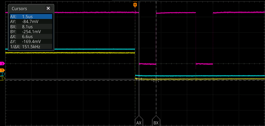
- Horizontal axis: (10µs/DIV)
- Pink: From the start of the interrupt handler until the GINT detection edge is reconfigured (1V/div)
- Cyan/Yellow: Input signal (2V/div)
If another pin changes during the interrupt handler, example 1
In this example, another pin (cyan) changed during the first part of the interrupt handler, so it was processed consistently within the first handler. The behavior is the same as the simultaneous change mentioned above. The changes of both the yellow and cyan pins are communicated to the application in the first interrupt.
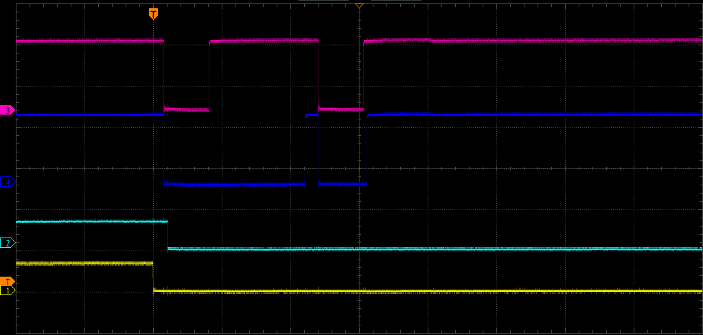
- Horizontal axis: (10µs/DIV)
- Pink: From the start of the interrupt handler until the GINT detection edge is reconfigured (2V/div)
- Blue: From the start to the end of the interrupt handler (2V/div)
- Cyan/Yellow: Input signal (5V/div)
If another pin changes during the interrupt handler, example 2
In this example, another pin (cyan) changes during the interrupt handler, but since the change occurs after the detection edge has been reconfigured, an interrupt occurs immediately afterward. A third handler is executed after the second handler finishes. The change of the yellow pin is communicated to the application in the first interrupt, and the change of the cyan pin is communicated in the second interrupt.
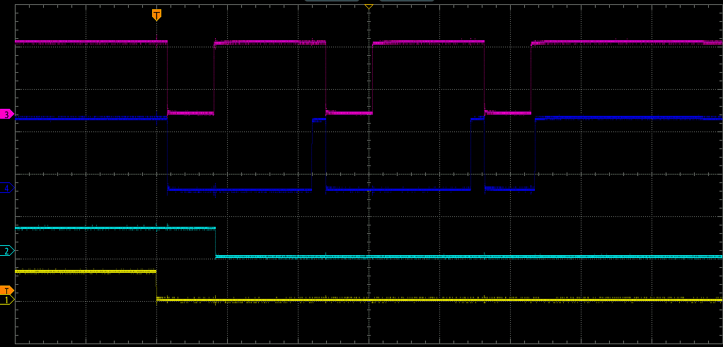
- Horizontal axis: (10µs/DIV)
- Pink: From the start of the interrupt handler until the GINT detection edge is reconfigured (2V/div)
- Blue: From the start to the end of the interrupt handler (2V/div)
- Cyan/Yellow: Input signal (5V/div)