Matchstick Antenna Data Sheet
Latest Version
Product Overview
A matchstick antenna dedicated to the TWELITE series.
Main Features
- Antenna dedicated to TWELITE Twilight and wire antenna types. (Cannot be connected to coaxial connector types.)
- Can also be used bent. (When standing upright, it has characteristics closer to a dipole.)
- Environmental consideration: RoHS compliant
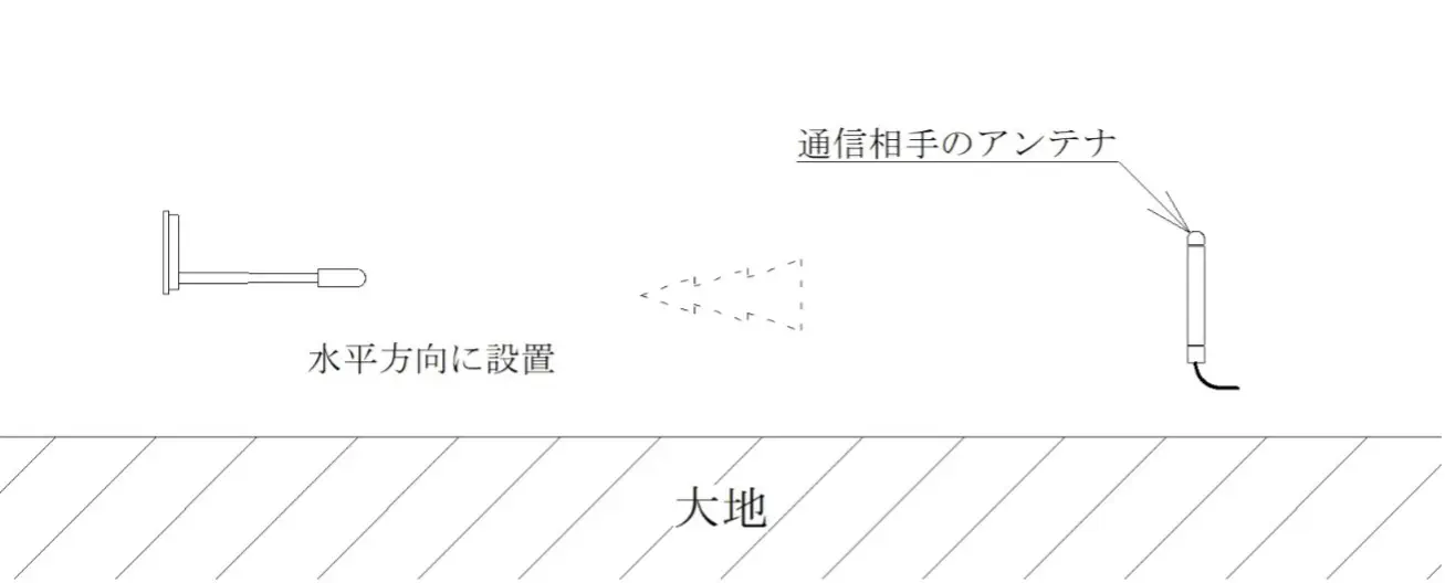
Standard Installation Method
- To obtain similar radiation characteristics (omnidirectional) in all directions, install the matchstick antenna vertically as shown in the figure.
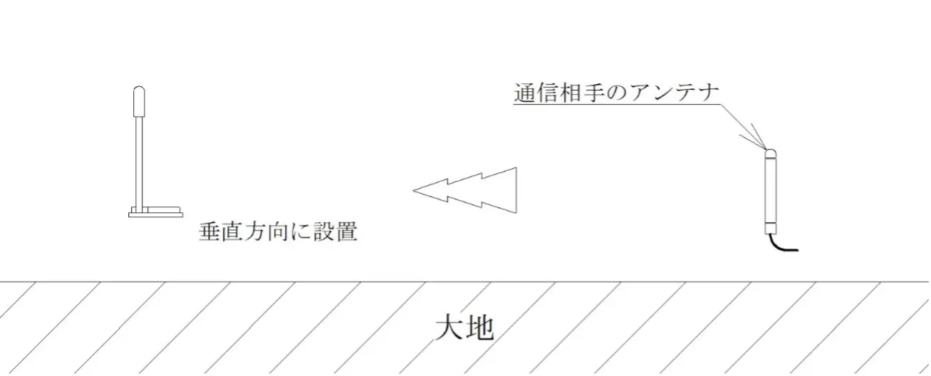
- When the matchstick antenna is installed horizontally, omnidirectionality cannot be obtained.
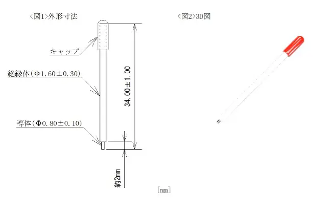
External Dimensions
- Outline drawing and dimensions
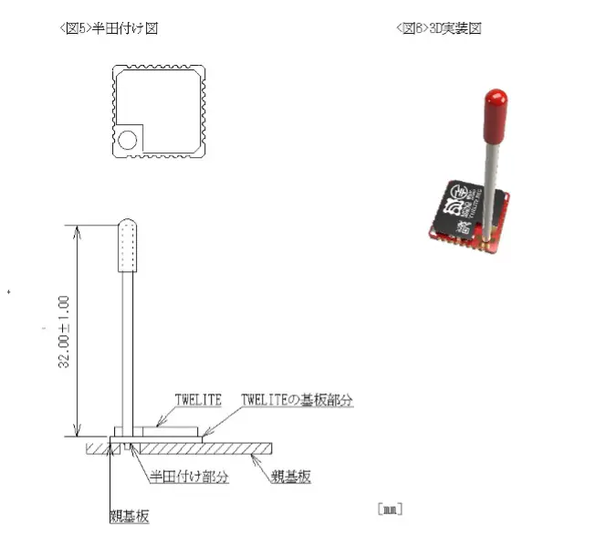
- MW-A-W0 Mounting diagram
Due to transportation, the conductor may move, causing the length of the exposed conductor to change. Adjust the length of the exposed conductor as necessary by pressing the cap head or other means.
Mounting Example
- The shape, design, and board thickness of the printed circuit board in <Figures 7~8> are examples and can be changed according to the application. To ensure antenna performance, wiring and electronic components (sensors, switches, etc.) are usually placed on the TWELITE mounting side, and the opposite side has a solid GND and battery holder.
- <Figures 7~8> are transparent views.
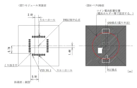
Mounting example of printed circuit board (FR-4 t=1.6)
Specifications
| Model Number | MW-A-W0 |
|---|---|
| Gain | Nominal 2.0 [dBi] <Note 1> |
| Operating Temperature Range | Wire: -40 |
| Connection Method | Insert into the wire antenna terminal and solder for use. |
Note 1: This is the radio certification application value based on measurements in all directions and may differ from the maximum value in the directivity chart below.
Directivity
- Directivity Measurement Method 1 (Standard Installation Method)
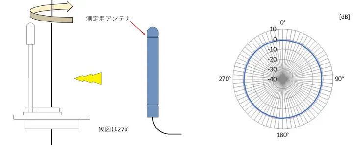
Maximum: -0.8[dB] Minimum: -1.4[dB] Average: -1.2[dB]
- Directivity Measurement Method 2
Maximum: -0.6[dB] Minimum: -17.4[dB] Average: -3.8[dB]
Note 3: 0[dB] in the directivity chart corresponds to the gain of a standard dipole antenna.
Note 4: TWELITE was mounted on the printed circuit board in <Figures 7~8> (solid GND size 30[mm]×30[mm]) to measure gain and directivity.
Remarks
- Gain and directivity vary depending on the solid GND size of the printed circuit board on which TWELITE is mounted, external wiring, batteries, and placement of electronic components (sensors, switches).
- If metal parts or wiring are placed around the MW-A-W0, antenna characteristics may be significantly affected. Examples with relatively small impact include resin, printed circuit boards without wiring (thickness: about 1~1.6[mm], material: FR-4, etc.), and resin screws.
- When using inside a case, a case thickness of about 1.5~2[mm] and materials such as ABS resin or polycarbonate are recommended.
- It is recommended that the solid GND size of the printed circuit board on which TWELITE is mounted be about 20[mm]×20[mm] to 40[mm]×40[mm].