Matchstick Antenna Data Sheet
v1.0.2
Product Overview
A matchstick antenna dedicated to the TWELITE series.
Main Features
- Antenna dedicated to TWELITE Twilight and wire antenna types. (Cannot be connected to coaxial connector types.)
- Can also be used bent. (When standing upright, it exhibits characteristics closer to a dipole.)
- Environmental consideration: RoHS compliant.
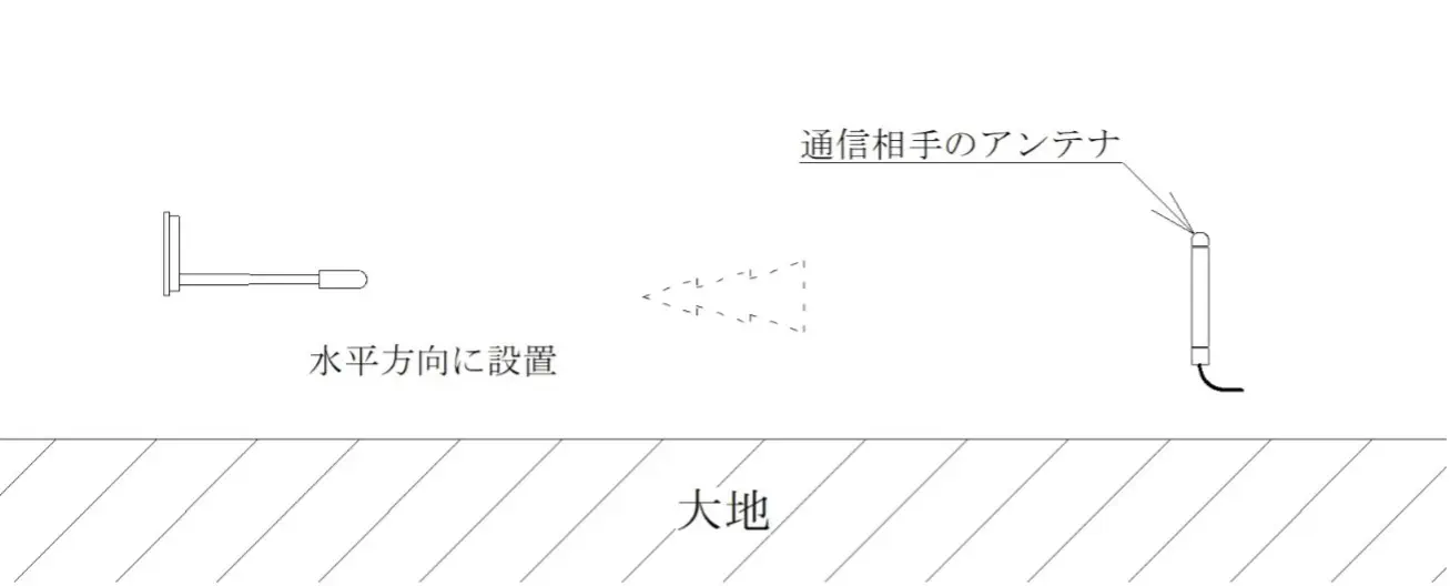
Standard Installation Method
- To obtain similar radiation characteristics (omnidirectional) in all directions, install the matchstick antenna vertically as shown in the figure.
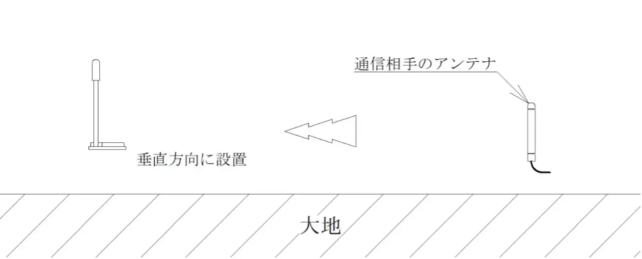
- When the matchstick antenna is installed horizontally, omnidirectionality cannot be obtained.
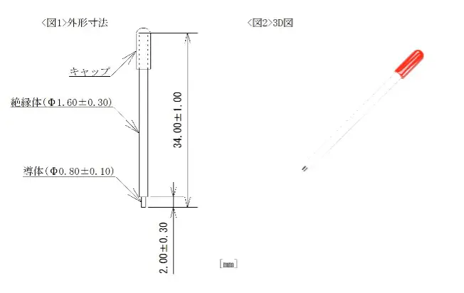
External Dimensions
- Outline drawing and dimensions
- MW-A-W0 mounting diagram
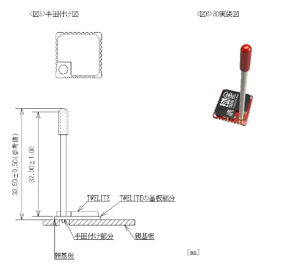
Mounting Example
- The shape, design, and board thickness of the printed circuit board in <Figures 7~8> are examples and can be changed according to the application. To ensure antenna performance, wiring and electronic components (sensors, switches, etc.) are usually placed on the TWELITE mounting side, and a solid GND and battery holder are placed on the opposite side.
- <Figures 7~8> are perspective views.
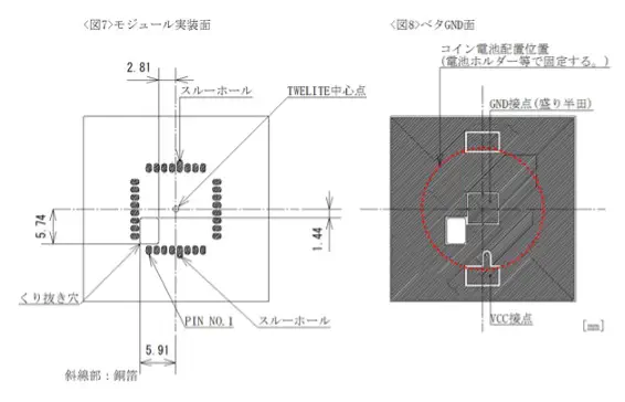
Mounting example of printed circuit board (FR-4 t=1.6)
Specifications
| Model Number | MW-A-W0 |
|---|---|
| Gain | Nominal 2.0 [dBi] <Note 1> |
| Operating Temperature Range | Wire: -40 |
| Connection Method | Insert into wire antenna terminal and solder for use. |
Note 1: The value for radio certification application is based on measurements in all directions and may differ from the maximum value in the directivity chart below.
Directivity
- Directivity Measurement Method 1 (Standard installation method)
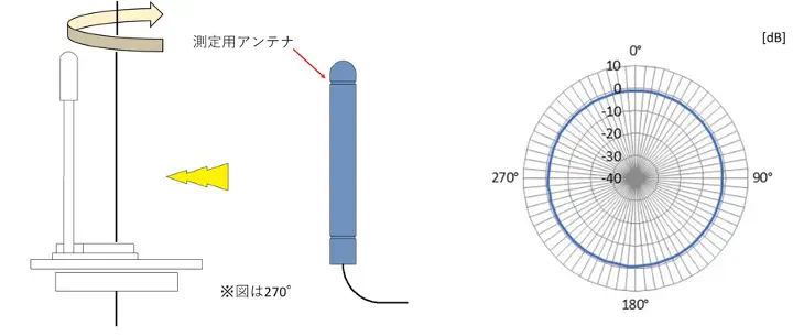
Maximum: -0.8[dB] Minimum: -1.4[dB] Average: -1.2[dB]
- Directivity Measurement Method 2
Maximum: -0.6[dB] Minimum: -17.4[dB] Average: -3.8[dB]
Note 3: 0[dB] on the directivity chart corresponds to the gain of a standard dipole antenna.
Note 4: TWELITE mounted on the printed circuit board in <Figures 7~8> (solid GND size 30[mm]×30[mm]) for gain and directivity measurement.
Remarks
- Gain and directivity vary depending on the solid GND size of the printed circuit board on which TWELITE is mounted, external wiring, battery, and placement of electronic components (sensors, switches).
- If metal parts or wiring are placed around the MW-A-W0, antenna characteristics may be significantly affected. Examples with relatively small influence include resin, printed circuit boards without wiring (thickness: about 1~1.6[mm], material: FR-4, etc.), and resin screws.
- When used in a case, a case thickness of about 1.5~2[mm] and materials such as ABS resin or polycarbonate are recommended.
- It is recommended that the solid GND size of the printed circuit board on which TWELITE is mounted be about 20[mm]×20[mm] to 40[mm]×40[mm].