Internal Embedded Planar Antenna Data Sheet
Overview
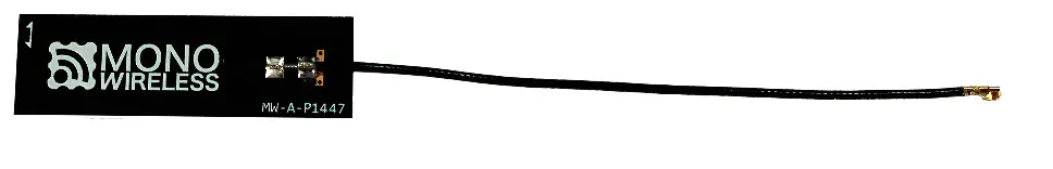
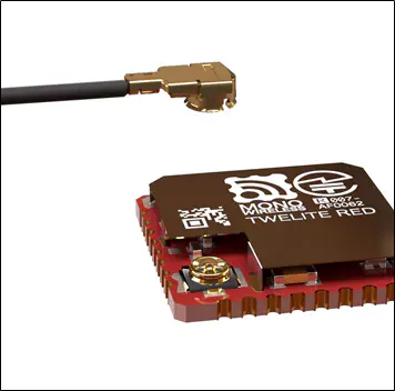
TWELITE series coaxial connector dedicated, internal embedded antenna.
Features
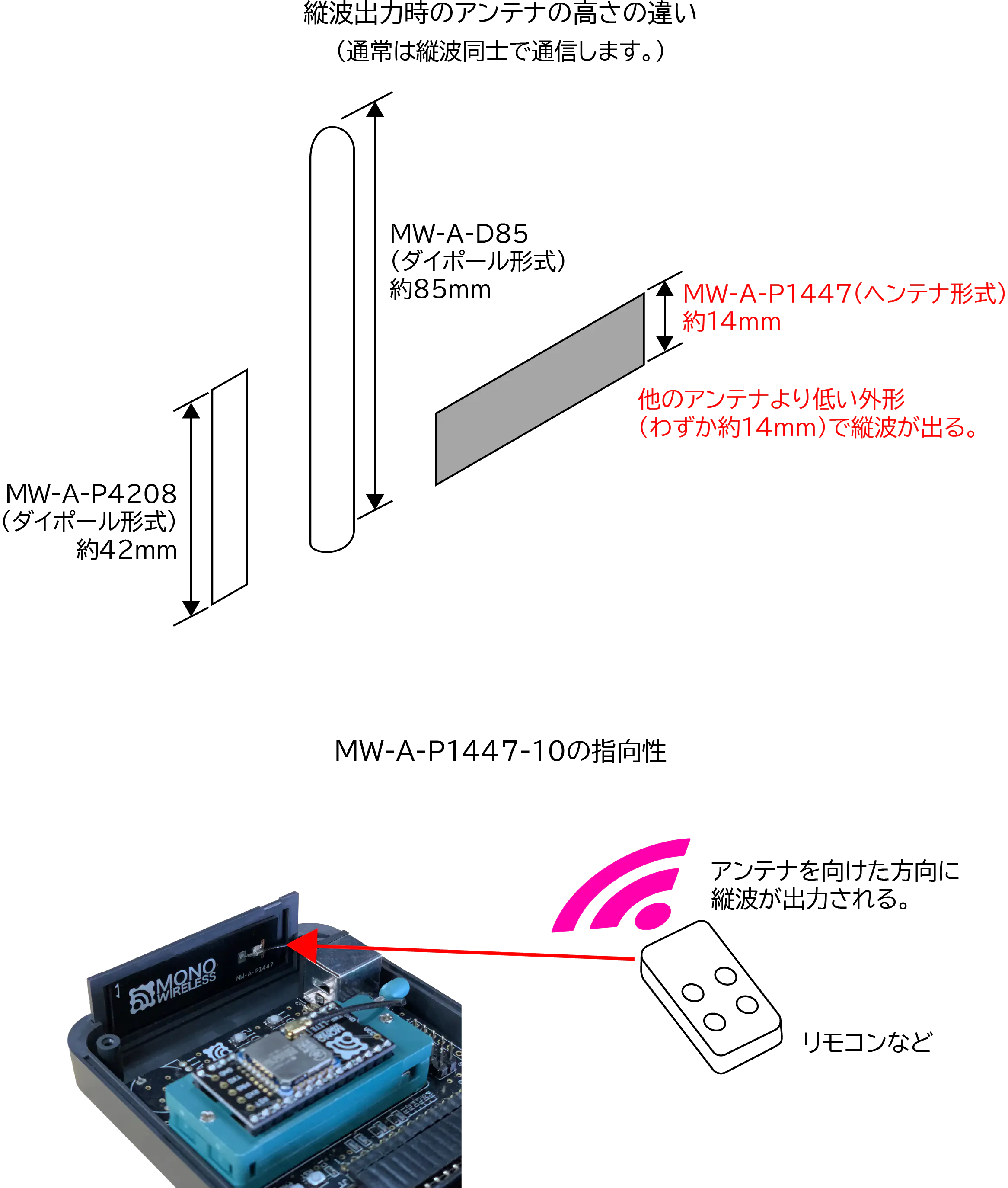
- Unlike conventional antennas, which require vertical installation to handle vertical polarization, this product uses the Hentenna method and radiates vertical polarization waves from both sides when installed horizontally.
- This product comes with double-sided tape attached, allowing it to be affixed inside an ABS resin case. It is suitable for use like a remote control without protrusions, radiating radio waves towards the communication partner.
Features
Standard Installation Method
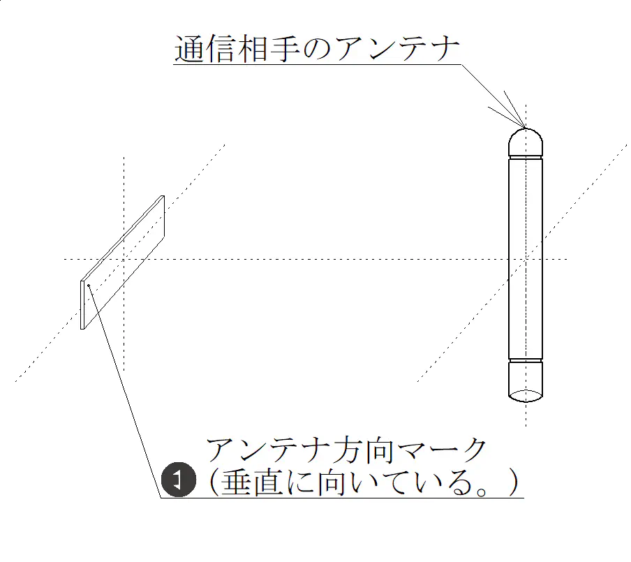
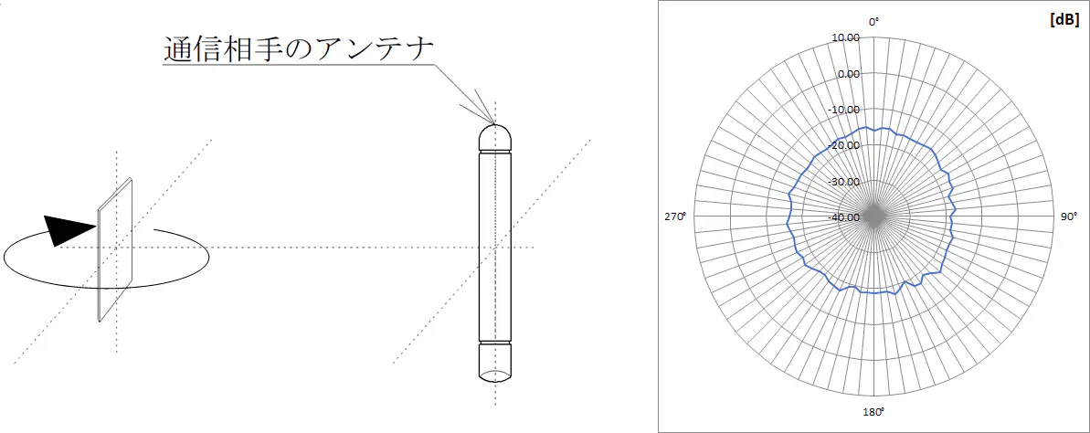
- Install this product facing the communication partner horizontally.
Even when installed horizontally, if the edge side faces the target, communication may become unstable.
Standard Installation Method
- When installed vertically, communication with the partner may become unstable.
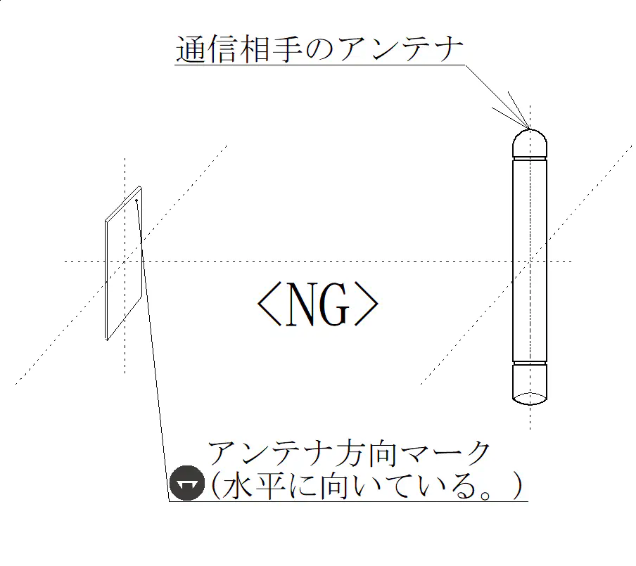
Non-standard Installation Method
Outline Drawing and Dimensions
Outline Drawing
Outline Drawing
Dimensions
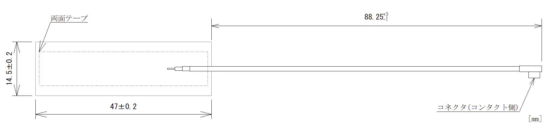
Dimensions
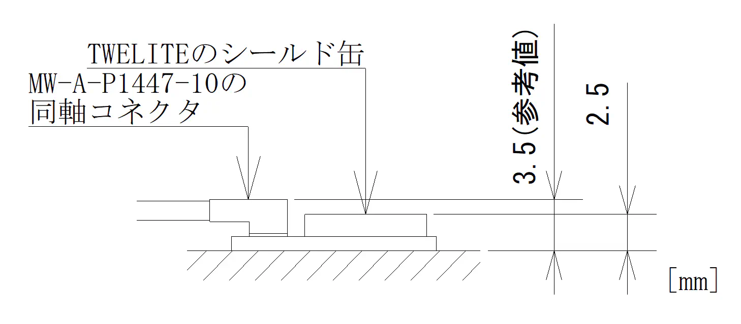
Overall Thickness After Coaxial Connector Connection
Specifications
| Model | MW-A-P1447-10 |
|---|---|
| Gain | 2.95 [dBi] <Note 1> |
| Connector | Seiko Instruments Inc. MHF I PLUG |
| Operating Temperature Range | -40 [℃] ~ 90 [℃] (Double-sided tape -10 [℃] ~ 60 [℃]) |
| Cable Bending Characteristics | Minimum bending radius 14[mm] |
| Connector Mating Cycles | 25 times |
| Double-sided Tape | Sekisui Chemical Co., Ltd. #5782 |
| Remarks | Double-sided tape attached on the back.1) Recommended to attach to ABS resin about 2 [mm] thick.2) Recommended to attach at room temperature. |
Note 1: The value is based on measurements in each direction for radio certification application and may differ from the maximum value in the directivity chart.
Directivity
- Directivity Measurement Method 1 (Standard Installation Method) ※ Logo side is at 180° direction
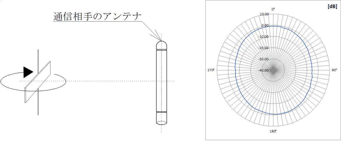
Directivity Measurement Method 1
| Maximum | Minimum | Average | Half Power Beamwidth |
|---|---|---|---|
| -0.59 [dB] | -6.40 [dB] | -3.24 [dB] | About 110° (Note 2) |
- Directivity Measurement Method 2 ※ Cable side is at 180° direction
Directivity Measurement Method 2
| Maximum | Minimum | Average | |
|---|---|---|---|
| -14.31 [dB] | -18.70 [dB] | -16.59 [dB] |
- Directivity Measurement Method 3 ※ Logo side is at 180° direction
Directivity Measurement Method 3
| Maximum | Minimum | Average | |
|---|---|---|---|
| -15.00 [dB] | -20.17 [dB] | -17.11 [dB] |
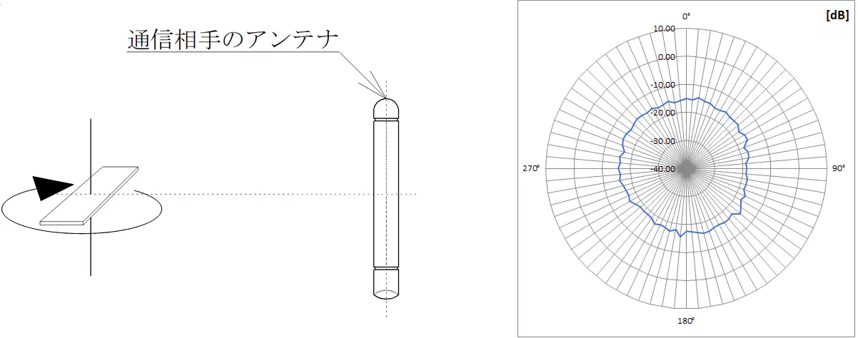
- Directivity Measurement Method 4 ※ Logo side is at 180° direction
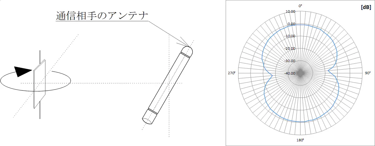
Directivity Measurement Method 4
| Maximum | Minimum | Average | Half Power Beamwidth |
|---|---|---|---|
| -0.53 [dB] | -17.68 [dB] | -4.98 [dB] | About 100° (Note 2) |
Note 2: Half power beamwidth based on the peak value on the logo side half. The half power beamwidth on the opposite side half is almost the same.
Note 3: 0 [dB] on the directivity chart represents the gain of a standard dipole antenna.
Connection Method
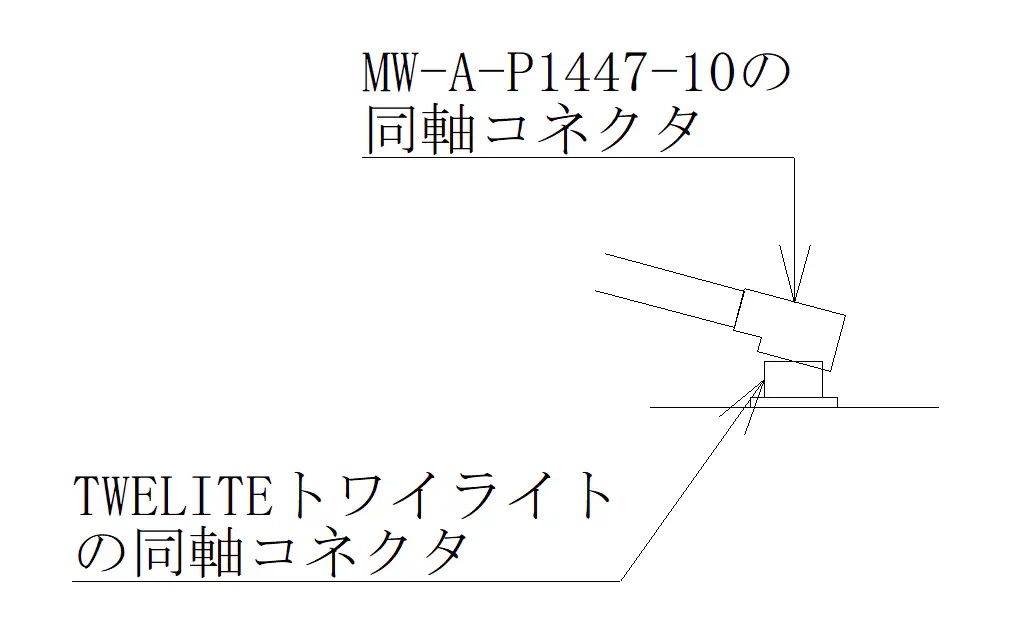
Align the centers of the coaxial connectors of the TWELITE and this product parallel as shown below, then fit only the tip to position it.
Correct Connection Method 1
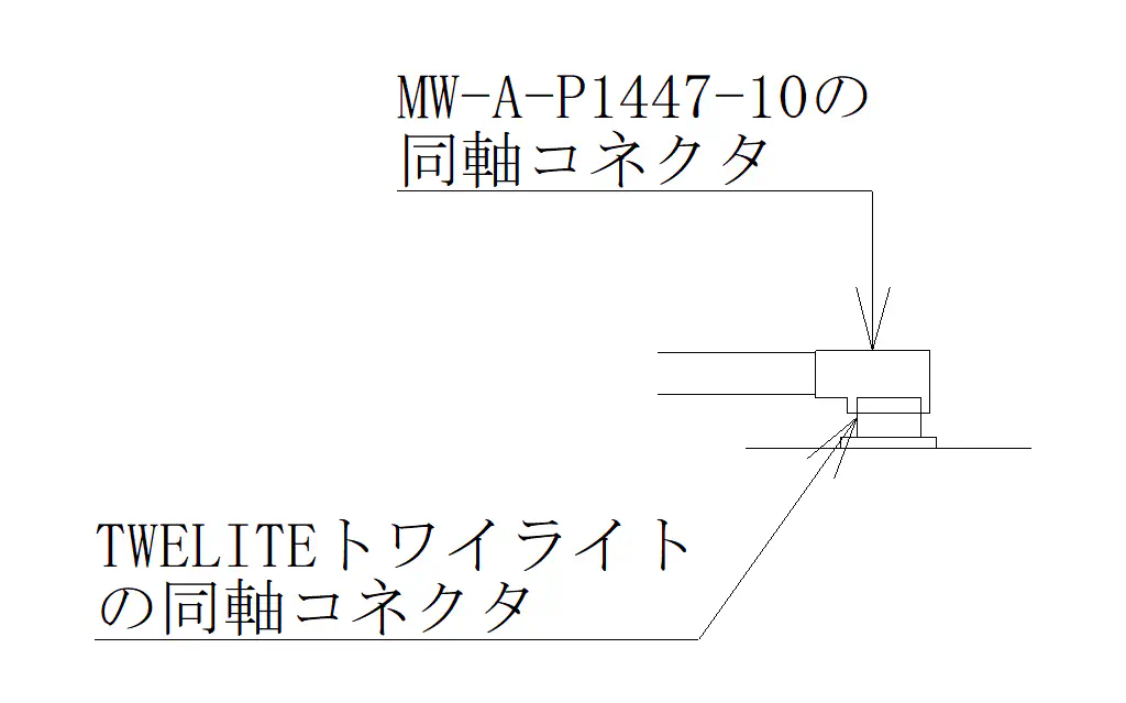
Correct Connection Method 2
If the coaxial connectors are misaligned during connection as shown below, it may cause damage to the coaxial connector.
Incorrect Connection Method 1
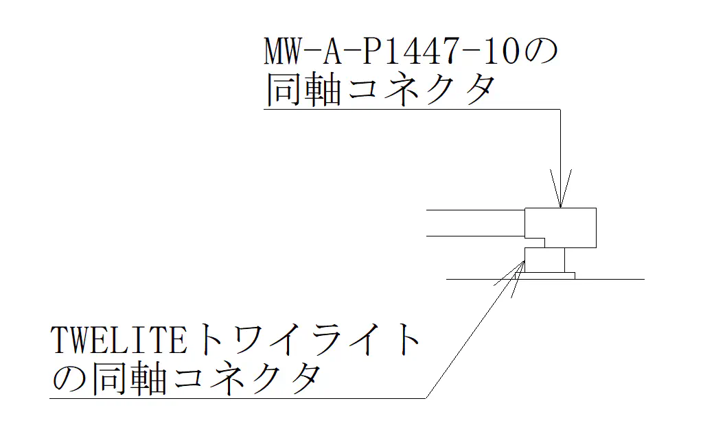
Incorrect Connection Method 2
Push the center of the coaxial connector gradually from directly above with your fingertip as shown below; connection is complete when you hear a “click” sound.
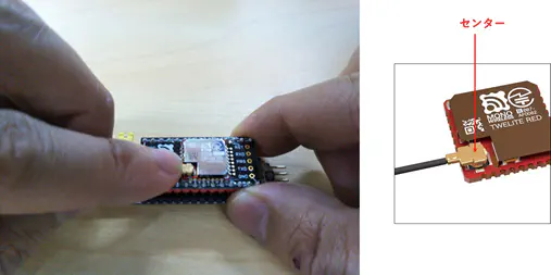
During Connection
Remarks
For connector removal, it is recommended to use the insertion/removal JIG (P/N:90224-001) made by Seiko Instruments Inc. ※ For the latest insertion/removal JIG, please contact Seiko Instruments Inc.
Example of mounting inside an ABS resin case.
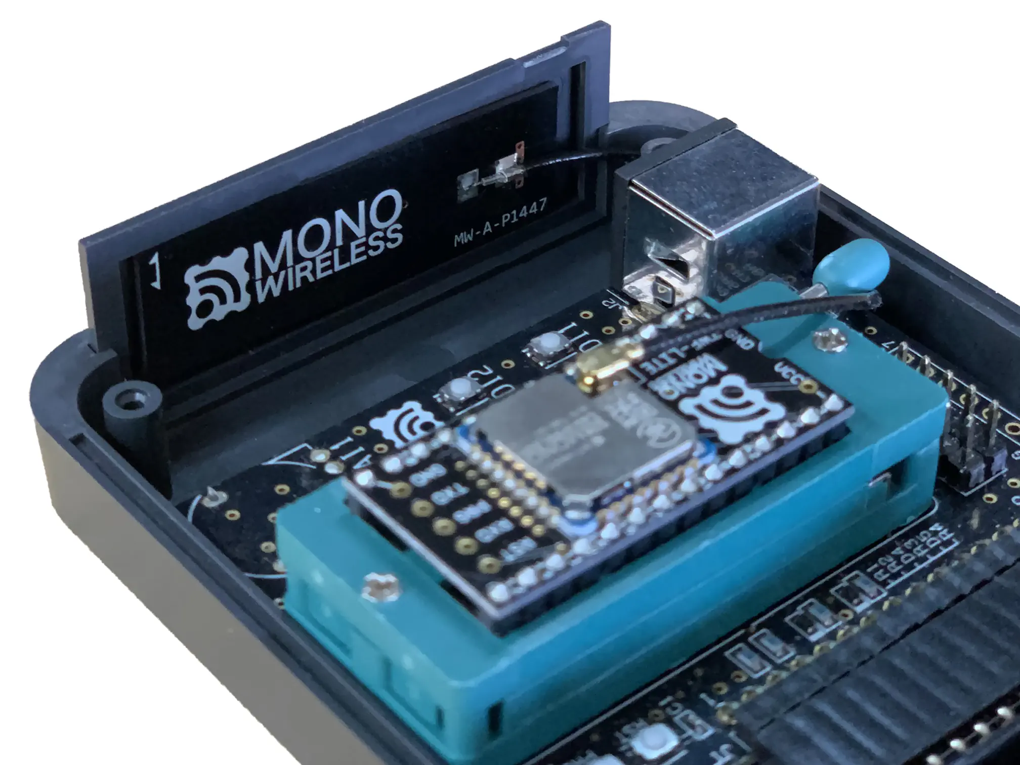
Mounting Inside Resin Case