Inverted-F PCB Antenna Data Sheet
Product Overview
A PCB antenna dedicated to the TWELITE series, designed for small tags.
Features
- Composed of a copper foil pattern on a printed circuit board (FR-4), enabling a compact, thin, and cost-effective design (antenna characteristics improve with compact design).
- Dedicated antenna for the TWELITE series (TWE-L-WX / MW-R-WX / MW-G-WX) (cannot be connected to coaxial connector types).
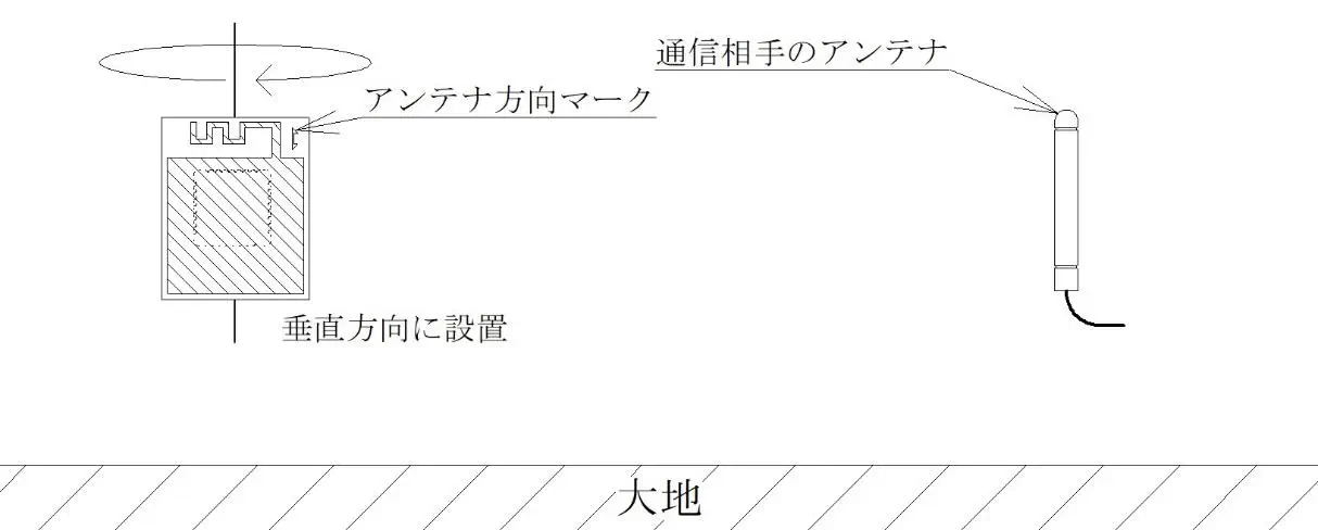
Standard Installation Method
- To obtain similar radio wave characteristics (omnidirectional) in all directions, install vertically as shown in the figure. For details on omnidirectionality, refer to the section “Directivity”.
Standard Installation Method
- When installed horizontally, omnidirectionality cannot be obtained.
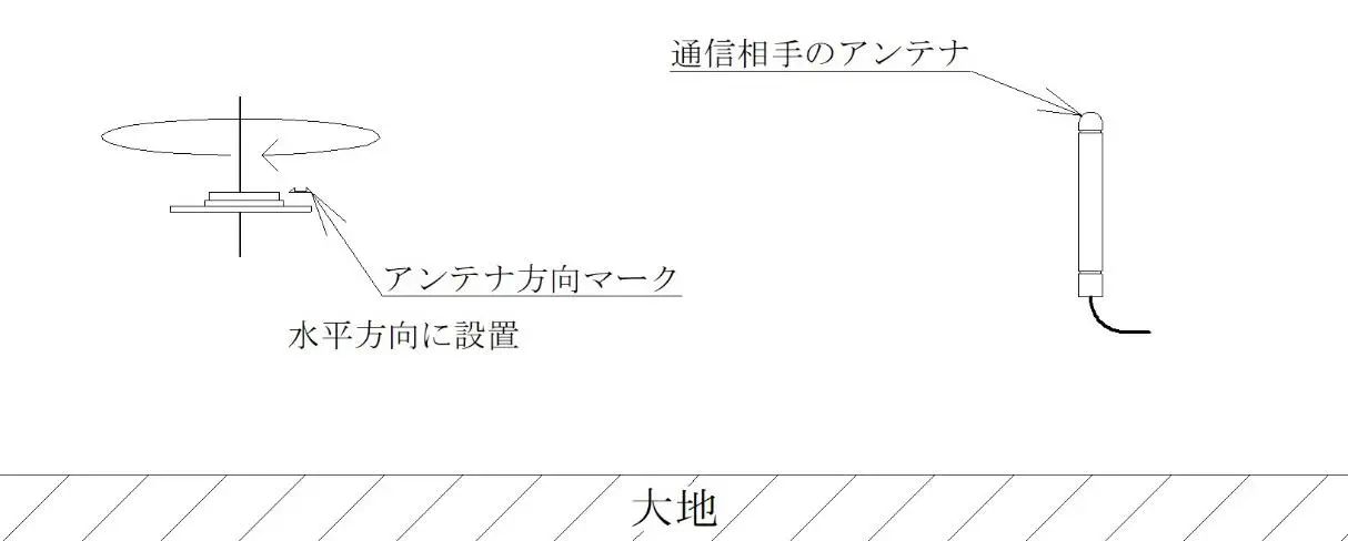
Non-standard Installation Method
Outline Drawing, Dimensions, and TWELITE Mounting Diagram
- Hatched area: copper foil formed on the printed circuit board.
- PCB substrate material: FR-4 (unchangeable)
- PCB substrate thickness: 0.5 [mm], 0.8 [mm], 1 [mm], 1.6 [mm] There are restrictions on the antenna pattern, PCB substrate thickness, and substrate material for radio certification. For details, refer to the section “About Radio Certification”.
- The antenna pattern is optimized for a PCB substrate thickness of 1 [mm], so characteristics slightly change if the substrate thickness differs. However, these changes are usually minimal. Characteristic patterns on a board based on an ideal GND size show changes of about 1–3 [dB].
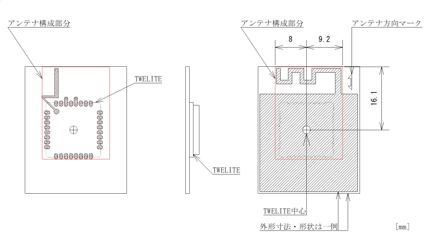
Outline Drawing and Dimensions
Specifications
| Model Number | MW-A-P1934 |
|---|---|
| Gain | Nominal 2.8 [dBi] <Note 1> |
Note 1: This is the radio certification application value based on measurements in all directions and may differ from the maximum value in the directivity chart below.
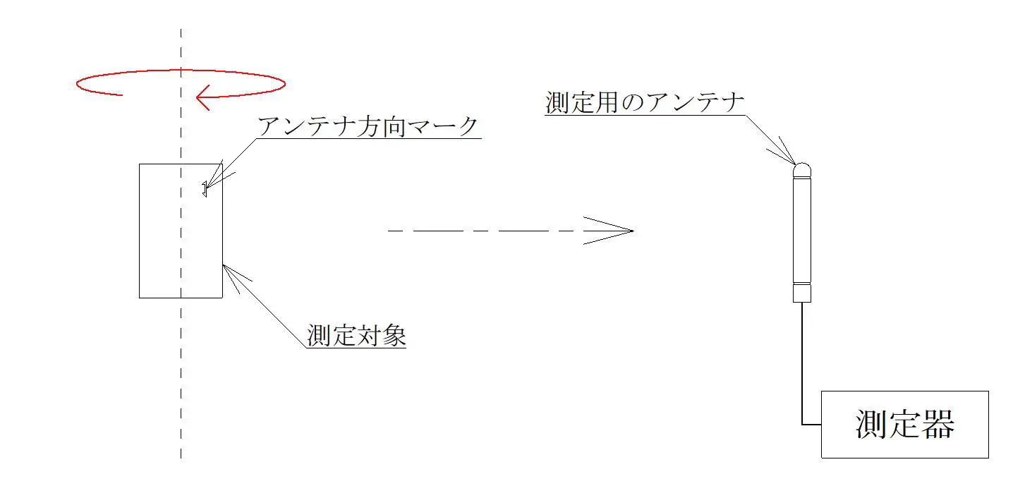
Directivity
Directivity Measurement Method 1 (Standard Installation Method)
- Measure the vertical plane
Vertical Plane Measurement
- Vertical plane directivity
| Maximum | Minimum | Average |
|---|---|---|
| -1.92 [dB] | -3.27 [dB] | -2.52 [dB] |
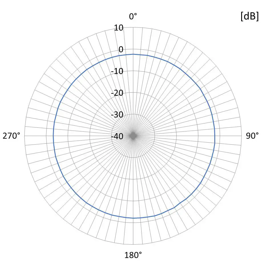
Vertical Plane Directivity
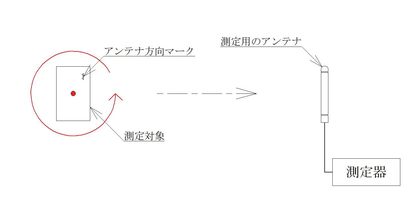
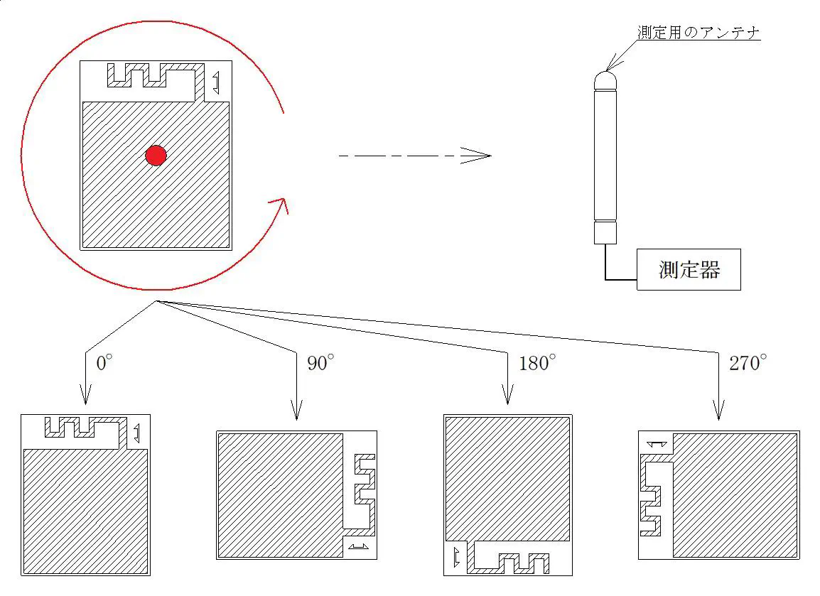
- Rotation direction of the measurement target and measurement angle
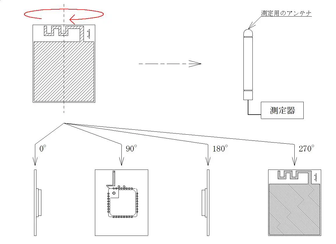
Rotation Direction of Measurement Target and Measurement Angle
Directivity Measurement Method 2
- Measure the horizontal plane
Horizontal Plane Measurement
- Horizontal plane directivity
| Maximum | Minimum | Average |
|---|---|---|
| -1.8 [dB] | -11.64 [dBi] | -4.88 [dBi] |
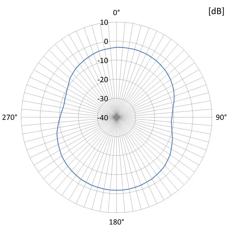
Horizontal Plane Directivity
- Rotation direction of the measurement target and measurement angle
Rotation Direction of Measurement Target and Measurement Angle
Note: 0 [dB] on the directivity chart corresponds to the gain of a standard dipole antenna. Note: TWELITE was mounted on a printed circuit board measuring 32.75 [mm] × 26.00 [mm] with a substrate thickness of 1 [mm], and gain and directivity were measured.
About Radio Certification
There are restrictions on the antenna pattern, PCB substrate material, and substrate thickness for radio certification.
In Japan, radio certification applications are made under the following conditions:
- Antenna pattern: design as shown in <Figure: Outline Drawing and Dimensions>
- PCB substrate material: FR-4
- PCB substrate thickness: 0.5 [mm], 0.8 [mm], 1.0 [mm], 1.6 [mm]
- Target modules: TWE-L-WX, MW-R-WX, MW-G-W
Outside Japan (FCC, CE), radio certification applications are made under the following conditions:
- Antenna pattern: design as shown in <Figure: Outline Drawing and Dimensions>
- PCB substrate material: FR-4
- PCB substrate thickness: 1 [mm]
- Target module: TWE-L-WX
For details, please refer to the URL below.
https://twelite.gitbook.io/general/radio-cert/design-revf-ant