TWE-EH SOLAR
Power radio transmission with the force of light!
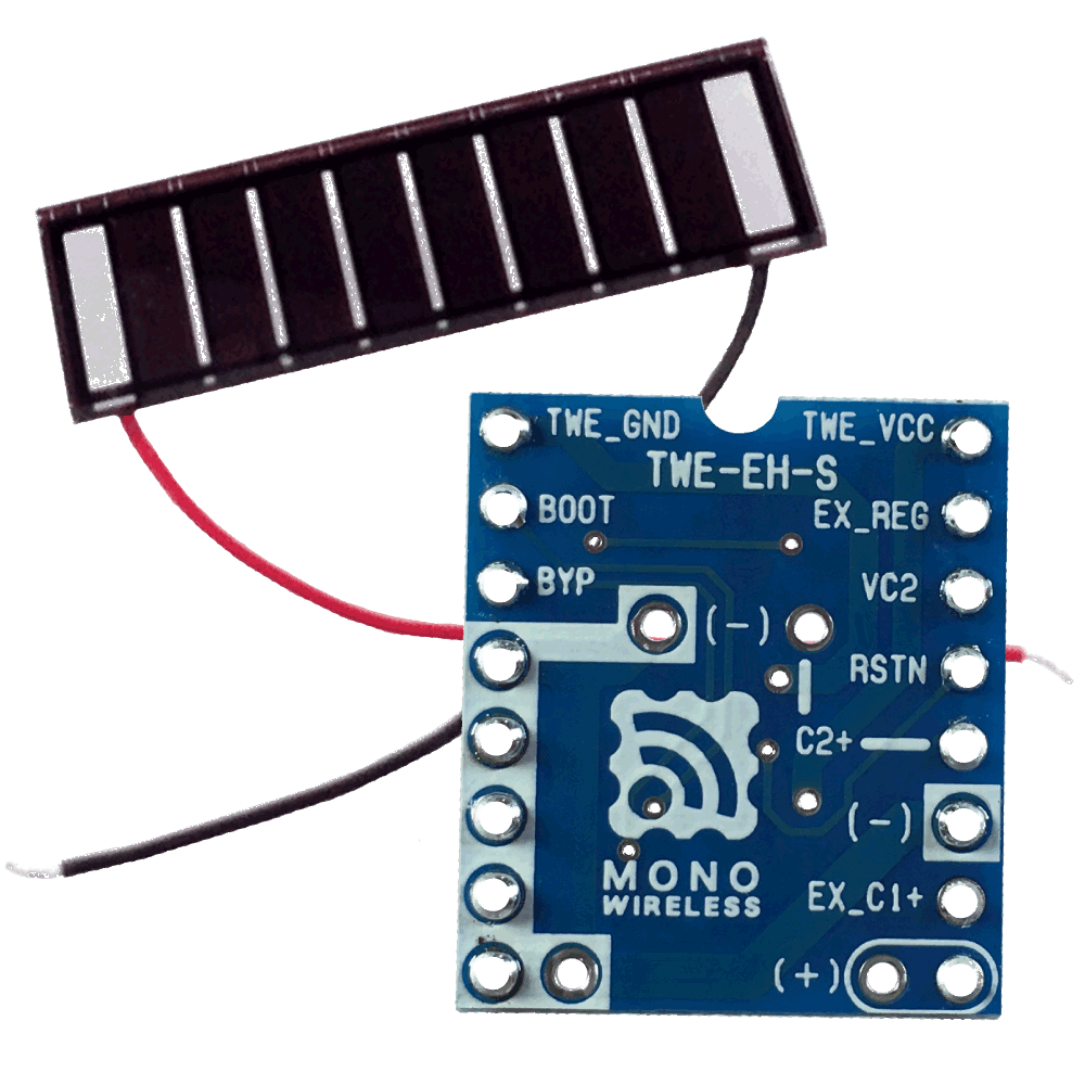
Dedicated to TWELITE series! Energy harvest control board TWE-EH-S
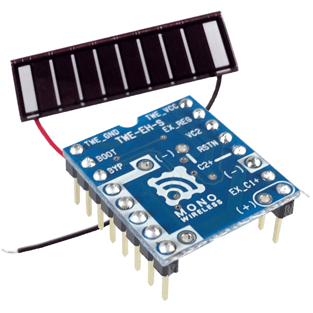
With pin headers
TWE-EH-S-DI
Without pin headers
TWE-EH-S-DP
Thank you for purchasing our product.
Features
- An energy harvest control board designed for use with TWELITE modules.
- Stores energy from solar panels in capacitors and uses that energy to operate wireless modules for very short periods.
- Built-in circuit charges excess energy to storage devices (electric double layer capacitors), enabling continuous operation even at night when solar panels are not generating power.
- Various solar panels can be used with external circuits or additional resistors.
AM-5815. Maximum output power is 6mW (5.2V - 1.1mA)Precautions for use
This evaluation board is designed to be used in combination with TWELITE modules.
Software acquisition
Please write the Wireless Tag App (App_Tag) firmware to TWELITE.
Available solar panels
As a guideline, solar panels with open-circuit voltage of 4V-6V and maximum output power of 300mW or less can be used.
To use solar panels with maximum output power of 10mW or more, connect an additional resistor \(R_{EX}\) between TWE_VCC and EX_REG. This prevents failure or fire due to overvoltage or overcurrent.
The value of the additional resistor \(R_{EX}\) can be calculated using the following formula:
The power rating of the additional resistor \(R_{EX}\) should be higher than the maximum output power of the solar panel.
Guidelines are shown below:
| Maximum output power [mW] | Resistor value \(R_{EX}\) [Ω] |
|---|---|
| 10 or less | Not required |
| 11-100 | 100 (1/4W) |
| 101-300 | 33 (1/2W) |
Let’s get it running!
Simple wireless thermometer
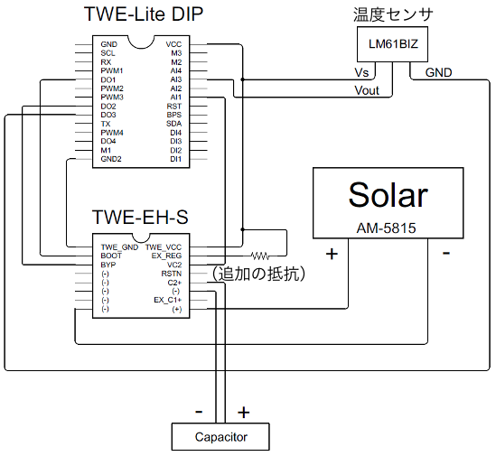
Please configure the circuit as follows:
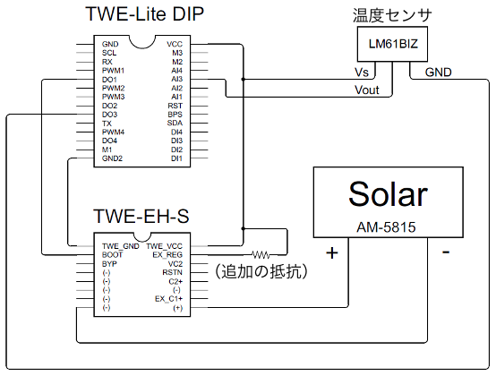
Example of transmitter circuit
By writing the Wireless Tag App (App_Tag) to the TWELITE module and setting the sensor type to 0x11 LM61 analog temperature sensor, data transmission can be performed.
For the parent device, write the Parent/Repeater App (App_Wings) and match the frequency channel and application ID.
How it works
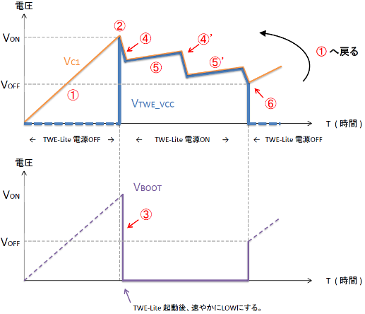
Voltage changes on each pin
- Energy from the solar panel is charged to the built-in capacitor
C1(220uF). - When the voltage \(V_{C1}\) of
C1reaches approximately 2.9V \(=V_{ON}\),TWE_VCCis connected toGNDand TWELITE starts operating. - TWELITE immediately sets the
DO1\(V_{BOOT}\) output to Low right after startup. - TWELITE performs wireless transmission.
- After wireless transmission, TWELITE enters sleep state.
- When the voltage drops below approximately 2.0V \(=V_{OFF}\) due to insufficient energy supply, TWELITE stops operating. The Low output of
DO1\(V_{BOOT}\) is released and returns to step 1.
In steps 4’ and 5’, it repeats the operation of wireless transmission after wake-up from sleep, then going back to sleep.
BOOT pin Low immediately after startup, it can be used with any act, etc., not just the wireless tag app.Pin assignment
| Signal name | Pin number | Pin number | Signal name | |
|---|---|---|---|---|
TWE_GND | 1 | 16 | TWE_VCC | |
BOOT | 2 | 15 | EX_REG | |
BYP | 3 | 14 | VC2 | |
(-) | 4 | 13 | RSTN | |
(-) | 5 | 12 | C2+ | |
(-) | 6 | 11 | (-) | |
(-) | 7 | 10 | EX_C1+ | |
(-) | 8 | 9 | (+) |
TWE_GND
Connect to TWELITE’s GND.
BOOT
Connect to TWELITE’s DO1.
For wireless tag app. For act, etc., connect to any pin
Set to Low state promptly after TWELITE startup. Voltage conditions follow TWELITE specifications.
BYP
Connect to TWELITE’s DO2.
For wireless tag app. For act, etc., connect to any pin
When set to High state, it bypasses the diode connected between the storage device and TWE_VCC.
When power is supplied to TWELITE with the storage device at 2.3V, TWE_VCC becomes approximately 2.0V due to diode voltage drop and operation stops. By bypassing, TWELITE can operate until the storage device voltage drops to approximately 2.0V. Voltage conditions follow TWELITE specifications.
GND / (-)
Connect the negative terminals of the solar panel, storage device, and capacitors added to EX_C1.
(+)
Connect the positive terminal of the solar panel.
EX_C1+
Connected to the positive terminal of the built-in capacitor C1 (220uF).
By adding a capacitor between EX_C1+ and GND, it is connected in parallel with the built-in capacitor C1 (220uF), increasing the capacity. The voltage range is 0-3.6V.
C2+
Connect a storage device for charging excess energy between C2+ and GND. The voltage range is 0-3.6V.
For connection details, see Making it work at night too!.
RSTN
Indicates TWELITE’s operating state. (Hi: Operating, Low: Stopped)
VC2
When monitoring the charging status of the storage device, connect to TWELITE’s AI1.
For wireless tag app. For act, etc., connect to any pin
VC2 divides the voltage of C2+ with two resistors (10MΩ). Additionally, to stabilize TWELITE’s voltage measurement, a 0.1uF capacitor is connected between VC2 and TWE_GND. By multiplying TWELITE’s VC2 reading by 2, you can obtain the storage device voltage.
EX_REG
TWE_VCC
Connect to TWELITE’s VCC.
Making it work at night too!
Simple wireless meter (with excess energy charging circuit)
With only C1, the wireless module’s operating time is limited, but by adding a capacitor to EX_C1+, the operating time can be extended.
Example of transmitter circuit