TWELITE CUE is a package that integrates the TWELITE wireless microcontroller, a 3-axis accelerometer, magnetic sensor, coin cell battery holder, and antenna. A dedicated CUE application (firmware) is pre-installed, and it starts operating immediately upon inserting a coin cell battery (CR2032). Its low power consumption allows continuous operation for years.
It is ideal for users who have ideas for utilizing wireless tags but lack hardware or software expertise, or have limited development resources.
TWELITE CUE is a compact wireless tag with long battery life and excellent transmission range.
Specifications
Product Code
The model numbers for TWELITE CUE are as follows.
| Common Name | Product Code | Remarks |
|---|---|---|
| TWELITE CUE (BLUE) | MW-B-CUE-0 | Standard Output |
| TWELITE CUE (RED) | MW-R-CUE-0 | High Output |
Wireless / Microcontroller Section
For specifications of the wireless and microcontroller section, refer to the TWELITE datasheet.
TWELITE CUE includes the following TWELITE modules:
| Model Number | Embedded TWELITE |
|---|---|
| MW-B-CUE-0 | TWE-L-WX |
| MW-R-CUE-0 | MW-R-WX |
Antenna
A reverse-F type antenna is used.
| Item | Specification |
|---|---|
| Antenna Type | MW-A-P1934 (datasheet) |
| Gain (typical, omni) | -1.4[dBi] (without case) / -2.5[dBi] (with case) |
| Polarization | Linear Polarization |
Vertical Directionality
Vertical Directionality
Horizontal Directionality
Horizontal Directionality
Certifications
| MW-B-CUE-0 | MW-R-CUE-0 | |
|---|---|---|
| Certification Type | TWE-001 Lite | TWELITE RED |
| Radio Law Approval No. | 007-AB0031 | 007-AF0062 |
| FCC ID | 2AINN-L1 | - |
| IC ID | 21544-L1 | - |
| Remarks | RoHS Compliant | RoHS Compliant |
Built-in Sensors
- Accelerometer: mCube MC3630
- Magnetic Sensor:
- Initial Version: Texas Instruments DRV5032FD
- From September 2022: Diodes Incorporated AH1390-HK4-7
- Watchdog Timer: Texas Instruments TPL5010
- LED: Rohm SML-D12D8WT86
Parts Description
1. TWELITE
Main wireless microcontroller module
2. LED
Acts as an indicator lamp for status
3. 7P Interface
7P Interface used for app configuration and writing
Below is the correspondence table for signal pins.
| Name | Signal | TWELITE DIP | TWELITE (SMD) | Description |
|---|---|---|---|---|
| GND | GND | 1, 14 | 20, 28, 30, 31, 32 | Negative terminal of power supply |
| TXD | DIO6 | 10 | 8 | Serial line (connect to RX on PC side) |
| PRG | SPIMISO | 7 | 2 | Connect to GND to reset; open or connect to VCC to enter programming mode |
| RXD | DIO7 | 3 | 9 | Serial line (connect to TX on PC side) |
| RST | RESETN | 21 | 21 | Connect to GND to reset |
| VCC | VCC | 28 | 5 | Positive terminal of power supply |
| SET | - | - | - | Extended control signal |
4. Accelerometer
Accelerometer for detecting XYZ acceleration
5. I2C Expansion Connector (initial lot only)
I2C Expansion Connector (initial lot only)
6. Magnetic sensor
Magnetic sensor for proximity detection of magnets (not a geomagnetic sensor)
7. Battery holder
Battery holder for CR2032
8. PCB Antenna
PCB Antenna constructed from circuit pattern on the board
Mechanical Drawings
Main Unit
Mechanical Drawing of the Main Unit
Case
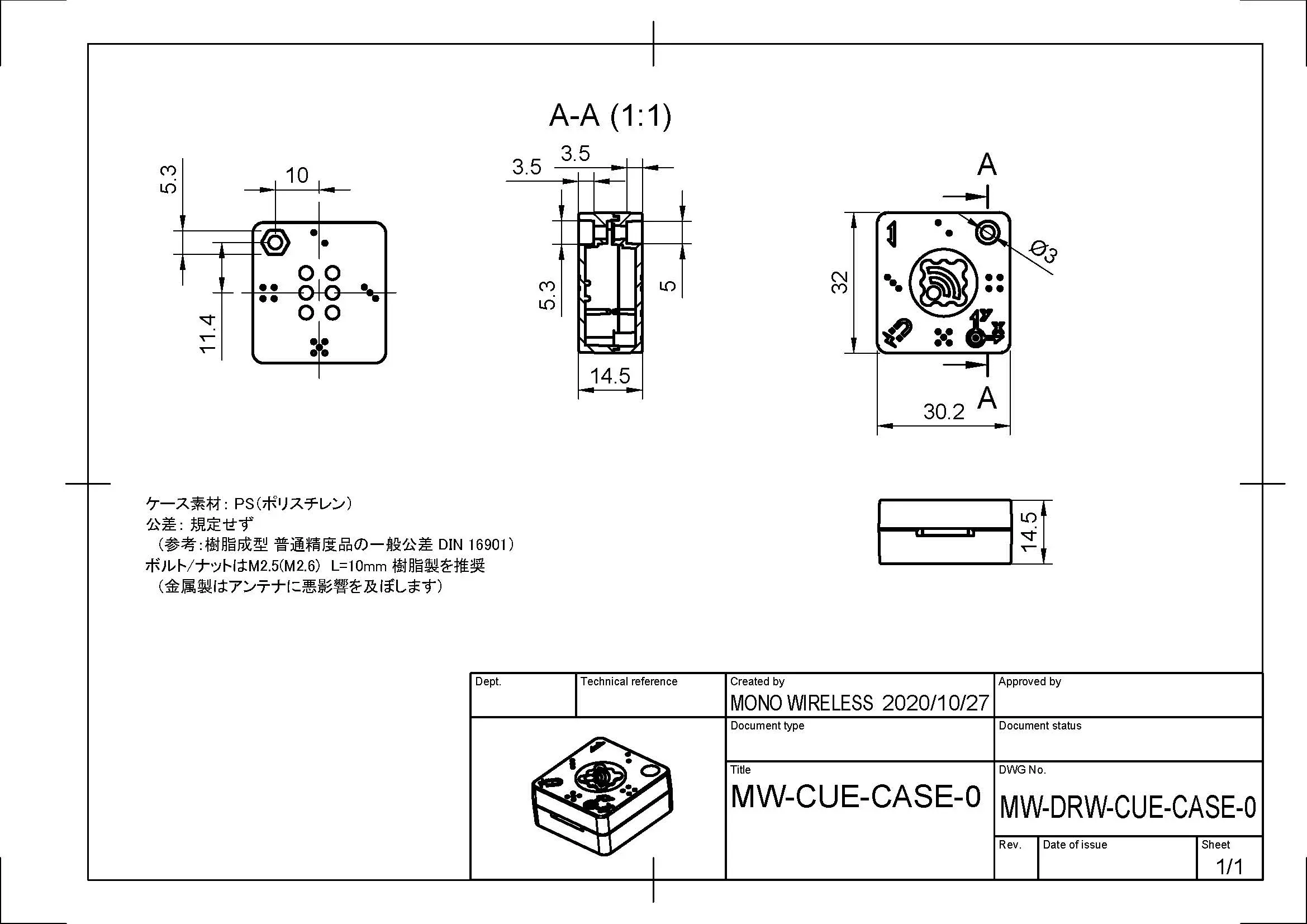
Mechanical Drawing of the Case
Circuit Diagram
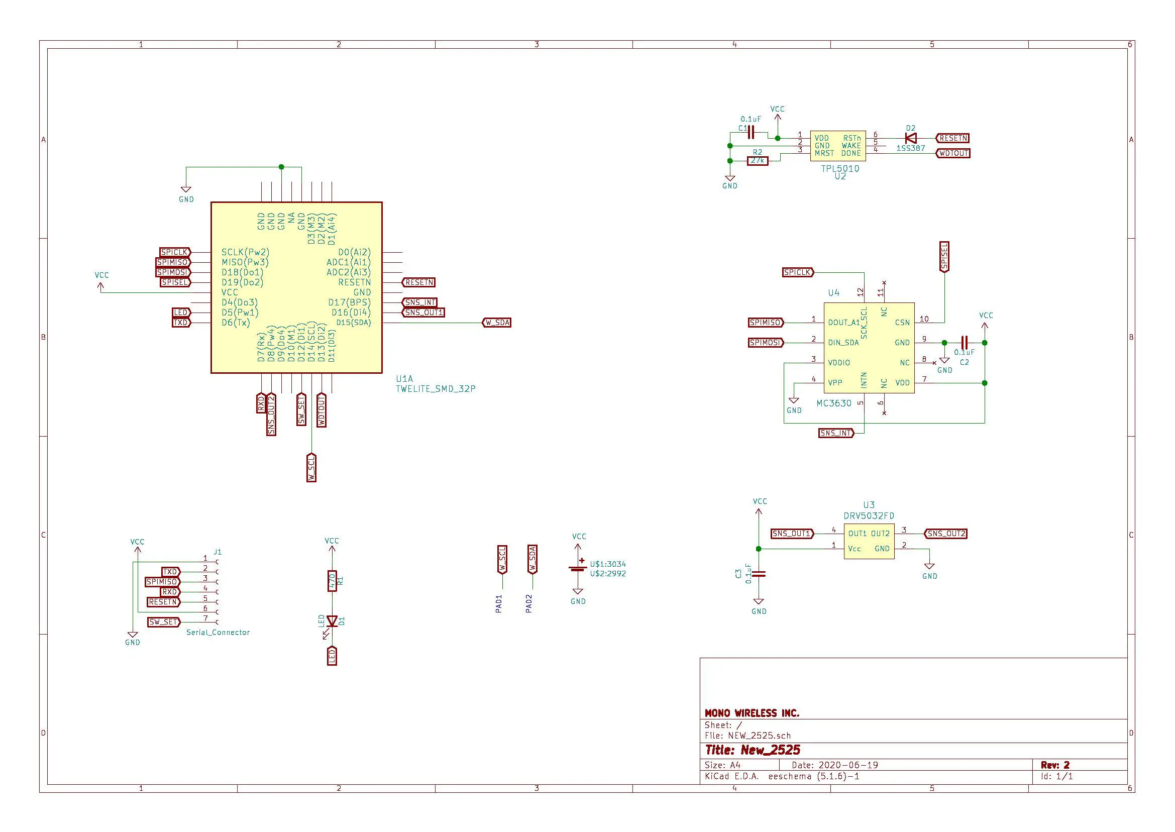
Circuit Diagram
Characteristics
TWELITE
Absolute Maximum Ratings
| Min | Max | ||
|---|---|---|---|
| Power Supply (VCC) | -0.3 | 3.6 | V |
| Analog IO (VREF/ADC) | -0.3 | VCC+0.3 | V |
| Digital IO | -0.3 | VCC+0.3 | V |
Recommended Operating Conditions
| Condition | Min | Typ | Max | ||
|---|---|---|---|---|---|
| Supply Voltage | 2.0 | 3.0 | 3.6 | V | |
| Start-up Voltage | 2.05 | V | |||
| Operating Temperature | No condensation | -20 | 75 | °C | |
| Operating Humidity | No condensation | 85 | %RH |
Current Consumption
| Condition | Min | Typ | Max | ||
|---|---|---|---|---|---|
| Sleep (RAM OFF, no timer) | 0.1 | uA | |||
| Sleep (RAM ON, with timer) | 1.5 | uA | |||
| Tx (CPU doze) | MW-B-CUE-0 | 15.3 | mA | ||
| MW-R-CUE-0 | 23.3 | mA | |||
| Rx (CPU doze) | MW-B-CUE-0 | 17.0 | mA | ||
| MW-R-CUE-0 | 14.0 | mA |
I/O Characteristics
| Condition | Min | Typ | Max | ||
|---|---|---|---|---|---|
| DIO Internal Pull-up | 40 | 50 | 60 | kΩ | |
| DIO High Input | VCCx0.7 | VCC | V | ||
| DIO Low Input | -0.3 | VCCx0.27 | V | ||
| DIO Input Hysteresis | 200 | 310 | 400 | mV | |
| DIO High Output | VCCx0.8 | VCC | V | ||
| DIO Low Output | 0 | 0.4 | V | ||
| DIO Sink/Source Current | VCC 2.7~3.6V | 4 | mA | ||
| VCC 2.2~2.7V | 3 | mA | |||
| VCC 2.0~2.2V | 2.5 | mA |
Accelerometer
| Condition | Min | Typ | Max | ||
|---|---|---|---|---|---|
| Current Consumption | Sleep, Vcc=1.8V | 0.1 | uA | ||
| Ultra-Low Power, 25Hz, Vcc=1.8V | 0.9 | uA | |||
| Ultra-Low Power, 100Hz, Vcc=1.8V | 2.8 | uA | |||
| Measurement Range | -16 | 16 | G | ||
| Resolution | 12 | bit | |||
| Sampling Frequency | 1300 | Hz |
Magnetic Sensor
Initial Version
| Condition | Min | Typ | Max | ||
|---|---|---|---|---|---|
| Current Consumption | VCC=3V | 1.6 | 3.5 | uA | |
| Sampling Frequency | 20 | Hz | |||
| Magnetic Threshold | Approaching | ±1.5 | ±3 | ±4.8 | mT |
| Releasing | ±0.5 | ±1.5 | ±3 | mT |
Units Shipped After September 2022
| Condition | Min | Typ | Max | ||
|---|---|---|---|---|---|
| Current Consumption | VCC=3.6V | 2.2 | 13 | uA | |
| Sampling Interval | 30 | 45 | 80 | ms | |
| Magnetic Threshold | When S-pole approaches | 6 | 17 | 25 | Gauss |
| When N-pole approaches | -25 | -17 | -6 | Gauss | |
| When S-pole is removed | 2 | 11 | 20 | Gauss | |
| When N-pole is removed | -20 | -11 | -2 | Gauss |
Watchdog Timer
| Condition | Min | Typ | Max | ||
|---|---|---|---|---|---|
| Current Consumption | 35 | 50 | nA | ||
| Pulse Interval | 60 | 90 | 120 | s |
LED
| Condition | Min | Typ | Max | ||
|---|---|---|---|---|---|
| Emission Wavelength | VCC=2.2V | 602 | 605 | 608 | nm |
| Luminous Intensity | VCC=2.2V | 40 | 100 | mcd | |
| Limiting Resistor | 470 | Ω |
Precautions
Inserting the Coin Cell
Insert the CR2032 battery with the + side facing the + mark on the battery holder. The TWELITE CUE LED will blink three times if inserted correctly.
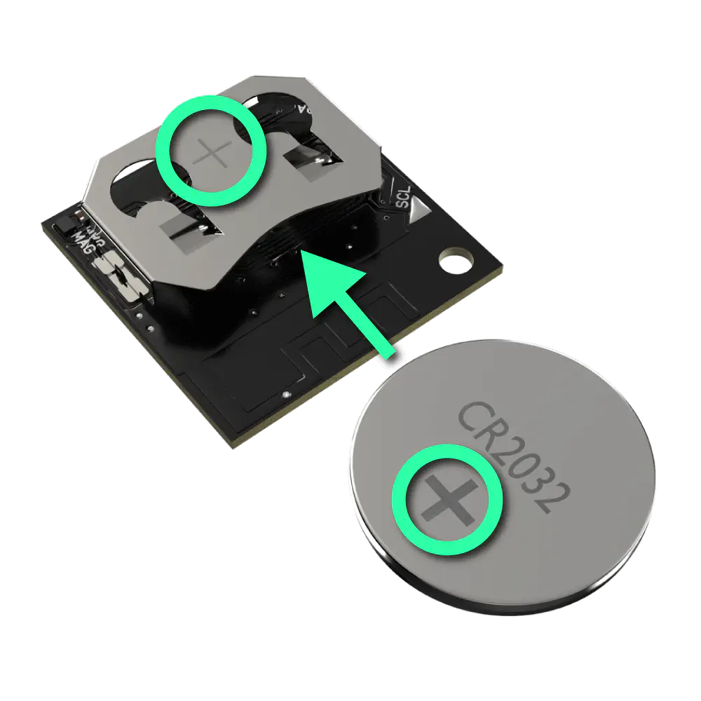
Battery Insertion Orientation
Due to its structure, the battery holder of TWELITE CUE is prone to detachment at the soldered area. Please follow the precautions below:
- When removing the coin cell, it is recommended to gently press the battery holder from above to avoid stressing the soldered section.
- When operating TWELITE CUE, use a dedicated case to hold down the battery holder from above.
Disposal
Dispose of this device in accordance with your local municipality’s ordinances and regulations. Please consult your local authorities for details.
General Notes
When using our products, be sure to evaluate and verify them under the actual conditions of your intended use.
For applications requiring high reliability or involving human safety, please contact your distributor in advance.
Revision History
| Version | Date | Description |
|---|---|---|
| 1.2.1 | 2024/5/7 | Added Parts Description |
| 1.2.0 | 2024/2/27 | Added information about current magnetic sensor |
| 1.1.1 | 2024/2/27 | Migrated to new website, minor edits |
| 1.1.0 | 2020/12/10 | Added information on antenna directionality |
| 1.0.0 | 2020/12/3 | Initial version |