TWELITE R is an adapter for USB connection. It is used to connect to a PC via USB for advanced application settings and writing applications.
This is the multi-page printable view of this section. Click here to print...
For suitable output, we recommend to use Google Chrome (15+) or Microsoft Edge (79+).
TWELITE R
USB Adapter
- 1: TWELITE R2
- 1.1: TWELITE R2 Datasheet
- 2: TWELITE R3
- 2.1: TWELITE R3 Datasheet
1 - TWELITE R2
Model: MW-LITER2
TWELITE R2 is an adapter that connects TWELITE to a PC via USB. It is used for detailed application settings and writing applications.
1.1 - TWELITE R2 Datasheet
Latest Edition
TWELITE R2 is an adapter for connecting TWELITE DIP and TWELITE PAL via USB.
It enables communication with TWELITE DIP/PAL from a computer over USB and is used for application configuration and programming.
Features
- Compatible with TWELITE series such as TWELITE DIP and TWELITE PAL
- Enables configuration and application rewriting of the TWELITE series on a PC
- Can supply power to TWELITE from a mobile battery or USB power source
- RoHS compliant, meeting new environmental standards
Precautions
About the DIP Connection Connector
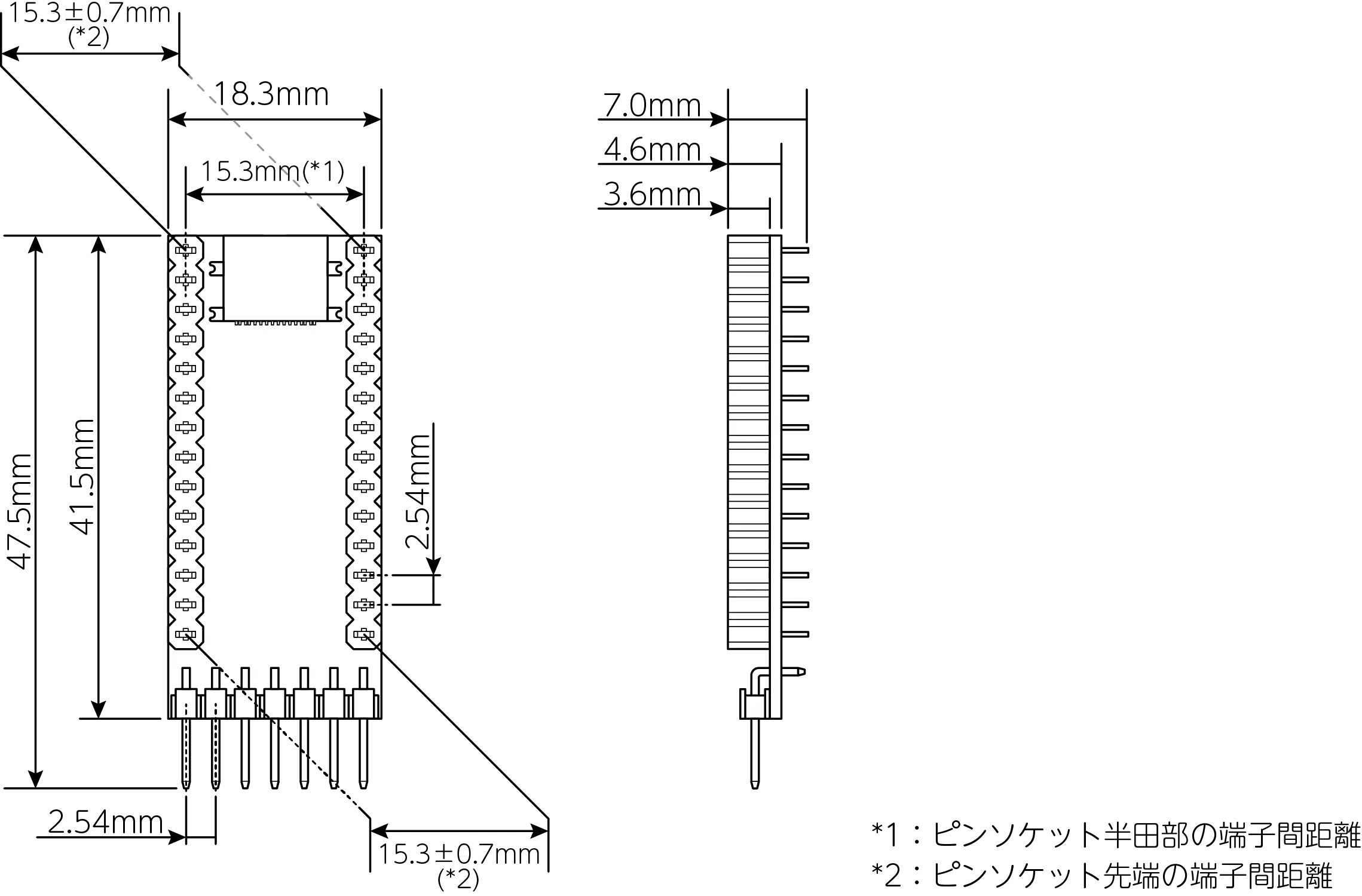
図1 外形図
As shown in Figure 1, the spacing between pins on the TWELITE DIP connection connector may vary by up to ±0.7 mm. When connecting TWELITE DIP to TWELITE R2, please bend the TWELITE DIP’s pin header slightly if needed before insertion, or use the dedicated TWELITE R attachment. Repeated insertion and removal of TWELITE DIP may result in poor connectivity.
Using the Attachment
A kit for converting the TWELITE R2’s DIP connector to a ZIF socket is sold separately.
If any of the following conditions apply to your use case, using the TWELITE R attachment is recommended.
- When a quick connection to TWELITE DIP is desired
- When TWELITE DIP is inserted and removed frequently
- When connecting TWELITE PAL to the DIP connector
Components
- USB Connector Type: USB Type-C* The USB connector manufacturer is subject to change without notice.
- USB-UART Conversion IC: FTDI FT230XQ
FT230XQ General-Purpose DIO Wiring
The general-purpose DIO wiring of FT230XQ is shown below.
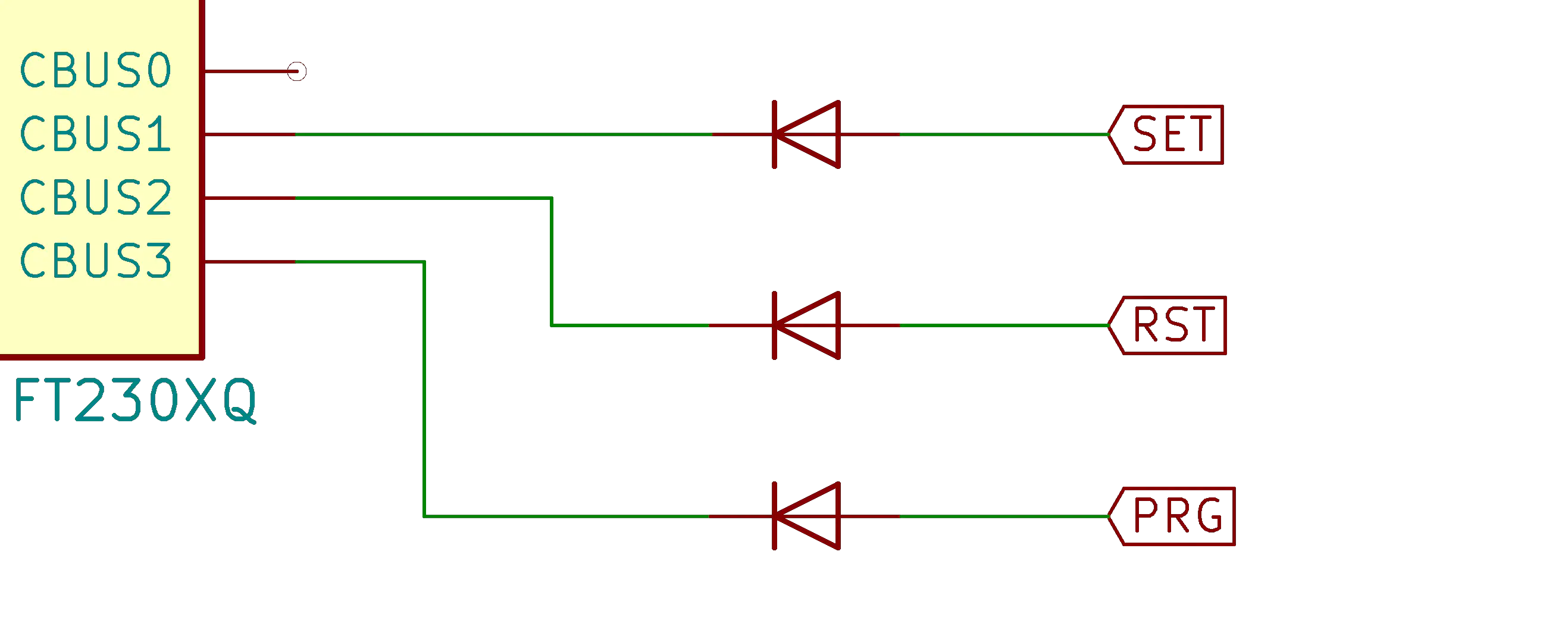
図2 汎用DIOの配線図
Also, SET, RST, and PRG are connected to the TWELITE DIP connector as shown below. The connections are as follows.
| Name on TWELITE R2 | Pin Number on TWELITE DIP Connector |
|---|---|
| SET | 15 |
| RST | 21 |
| PRG | 7 |
Absolute Maximum Ratings
| Min | Max | ||
|---|---|---|---|
| Power Supply (VCC) | -0.3 | 5.5 | V |
Characteristics
Recommended Operating Conditions
| Symbol | Condition | Min | Typ | Max | |||
|---|---|---|---|---|---|---|---|
| Power Supply Voltage | Vcc | 4.50 | 5.00 | 5.50 | V | ||
| Operating Temperature | TOPR | No condensation | -40 | 25 | 85 | °C |
- Values are based on the semiconductor datasheet.
DC Characteristics
| Symbol | Min | Typ | Max | Remarks | ||
|---|---|---|---|---|---|---|
| Current Consumption | Icc1 | 8.00 | mA | Excludes TWELITE current consumption | ||
| TWELITE Supply Voltage | Vto | 3.30 | V | |||
| TWELITE Supply Current | Ito | 50 | mA |
- Values are based on the semiconductor datasheet.
Revision History
| Version | Revision Date | Revision Details |
|---|---|---|
| 2.0.0 | 2023/05/15 | Changed to new format |
| 1.0.1 | 2020/6/1 | Added precautions, revised external diagram |
| 1.0.0 | 2020/3/13 | Initial version |
2 - TWELITE R3
Model: MW-LITER3
TWELITE R3 is an adapter that connects TWELITE to a PC via USB. It is used for detailed application configuration and programming.
2.1 - TWELITE R3 Datasheet
Latest Edition
TWELITE R3 is an adapter that connects TWELITE models with a 7P interface, such as TWELITE CUE and TWELITE ARIA, to a PC via USB.
It enables communication with TWELITE CUE/ARIA over USB and is also used for application configuration and programming.
Features
- Compatible with TWELITE series such as TWELITE CUE and TWELITE ARIA
- Enables configuration and rewriting of applications for TWELITE series on a PC
- Can supply power to TWELITE from a mobile battery or USB power source
- Compliant with RoHS, conforming to new environmental standards
Components
- USB Connector Type: USB Type-CThe manufacturer of the USB connector used is subject to change without notice.
- USB-UART Conversion IC: FTDI FT230XQ
Dimensions

Dimensions
Pin Assignment
The correspondence table of signal pins is as follows.
| TWELITER3Name | TWELITEName | TWELITEDIP# | TWELITESMD# | Description |
|---|---|---|---|---|
| GND | GND | 1, 14 | 20, 28, 30, 31, 32 | Negative side of power supply(one connection is sufficient) |
| TXD | TXD0 (DIO6) | 10 | 8 | Serial communication line(Connect to RX terminal on PC) |
| PRG | SPIMISO | 7 | 2 | Connect to GND for reset, then release or connect to VCC to enter programming mode |
| RXD | RXD0 (DIO7) | 3 | 9 | Serial communication line(Connect to TX terminal on PC) |
| RST | RESETN | 21 | 21 | Connect to GND to reset |
| VCC | VCC | 28 | 5 | Positive side of power supply(avoid collision with board power) |
| SET | DIO12 | 15 | 13 | Extended control signal(used for entering interactive mode on TWELITE CUE, etc.) |
When Using with TWELITE without a 7P Interface
When using TWELITE without a 7P interface, such as TWELITE DIP BLUE/RED, refer to the diagram below for wiring before use.
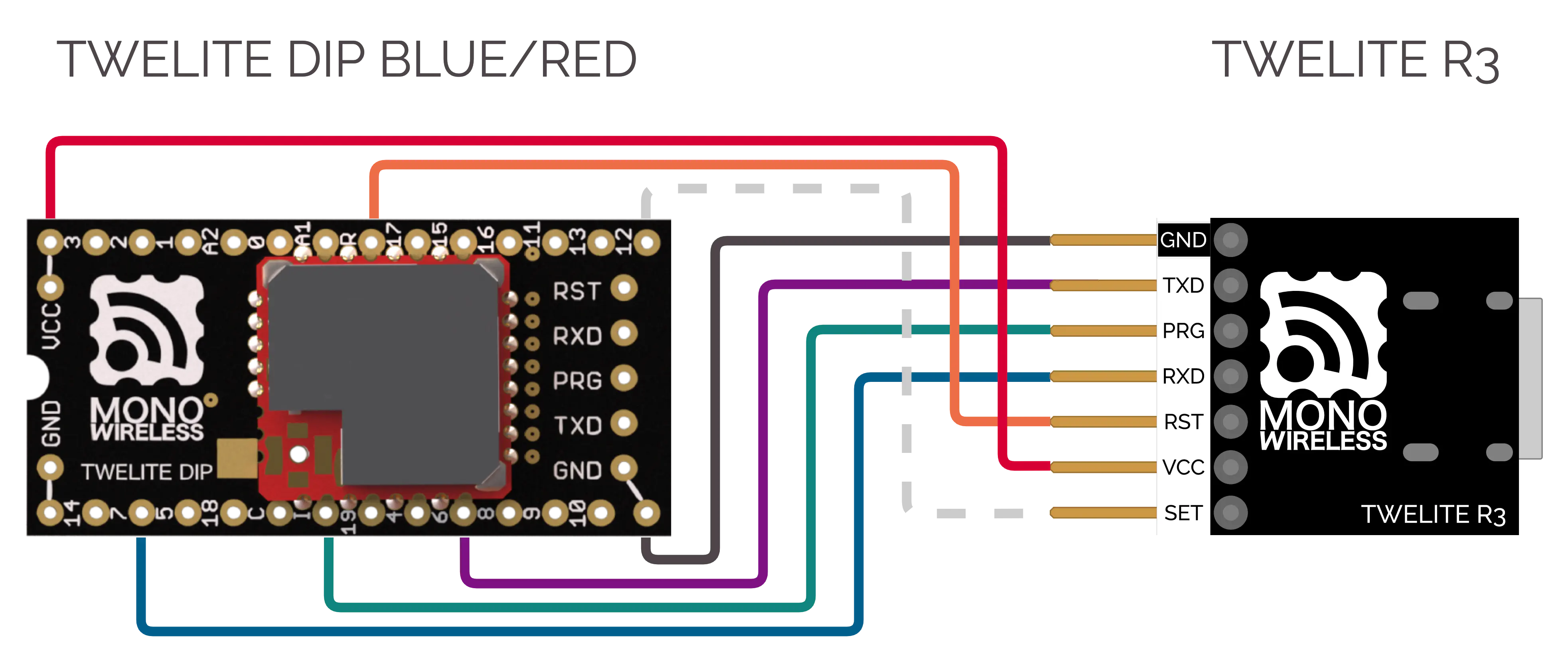
Connection with TWELITE DIP BLUE/RED
FT230XQ General-Purpose DIO Wiring
The general-purpose DIO wiring of FT230XQ is shown below.
Figure 2 General-Purpose DIO Wiring Diagram
Absolute Maximum Ratings
| Min | Max | ||
|---|---|---|---|
| Power Supply (VCC) | -0.3 | 5.5 | V |
Characteristics
Recommended Operating Conditions
| Symbol | Condition | Min | Typ | Max | |||
|---|---|---|---|---|---|---|---|
| Power Supply Voltage | Vcc | 4.50 | 5.00 | 5.50 | V | ||
| Operating Temperature | TOPR | No condensation | -40 | 25 | 85 | °C |
- Values are based on the semiconductor datasheet.
DC Characteristics
| Symbol | Min | Typ | Max | Remarks | ||
|---|---|---|---|---|---|---|
| Current Consumption | Icc1 | 8.00 | mA | Excludes TWELITE current consumption | ||
| TWELITE Supply Voltage | Vto | 3.30 | V | |||
| TWELITE Supply Current | Ito | 50 | mA |
- Values are based on the semiconductor datasheet.
Revision History
| Version | Revision Date | Revision Details |
|---|---|---|
| 2.0.0 | 2023/05/15 | Changed to new format |
| 1.0.0 | 2023/1/17 | Initial version |