TWELITE SPOT is a Wi-Fi gateway with a built-in TWELITE BLUE.
This is the multi-page printable view of this section. Click here to print...
For suitable output, we recommend to use Google Chrome (15+) or Microsoft Edge (79+).
TWELITE SPOT Datasheet
Wi-Fi Gateway
1 - TWELITE SPOT Datasheet
Latest Edition
The TWELITE® SPOT Wi-Fi gateway is a product that combines the low-power wireless microcontroller module TWELITE with the ESP32 wireless LAN microcontroller module. By developing firmware for the ESP32, it is possible to link the TWELITE network with the Wi-Fi network.
Please be sure to read Precautions before using the product.
For information on development, please refer to the Start Guide.
Features
- Compact package (45mm x 70mm x 22mm)
- Low power communication with many TWELITE series products via TWELITE NET
- Dedicated parent and relay device apps (App_Wings) pre-installed on TWELITE
- Equipped with widely used ESP32 wireless LAN module
- Free Arduino-based firmware development environment (ESP32)
- Arduino library MWings available for easy communication with TWELITE
- Easy-to-use USB-C power supply
- Case that can be easily mounted on walls with screws
- Built-in PCB antenna
- Approved under Japan’s ARIB STD-T66 technical standards (Giteki)
- RoHS compliant (10 substances)
Model Number
The model number of TWELITE SPOT is as follows. Please check the sales model number on our website before purchasing.
| Product Name | Model Number | Remarks |
|---|---|---|
| TWELITE SPOT | MW-B-SPOT-0 |
Major Components
TWELITE
- TWELITE BLUE (TWE-L-WX)
TWELITE Dedicated Antenna
| Item | Specification |
|---|---|
| Antenna Type | Inverted F Antenna (MW-A-P1934) |
| Gain (Typical on Omnidirectional Plane) | -4.0[dBi] (without case) / -3.0[dBi] (with case) |
| Polarization | Linear Polarization |
Vertical Radiation Pattern
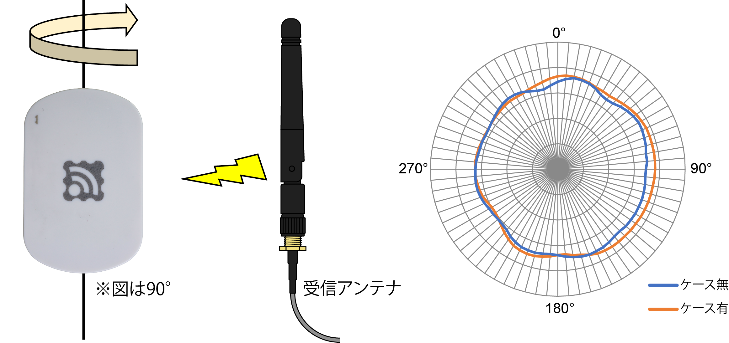
Vertical Radiation Pattern
Horizontal Radiation Pattern
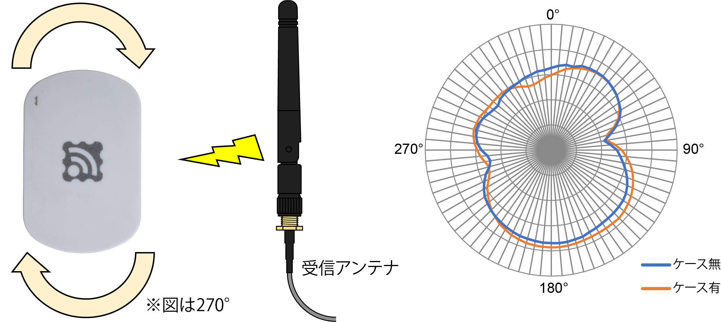
Horizontal Radiation Pattern
Wireless LAN Module
- Espressif Systems ESP32-WROOM-32E
Please refer to Espressif Systems’ datasheet for detailed specifications.
- The Wi-Fi module may be changed without notice.
Please refer to the Circuit Diagram in this document for the connection to TWELITE.
Enclosure
- Takachi Electronics Industry SIM5-7-2W
- The enclosure may be changed without notice.
Description of Components
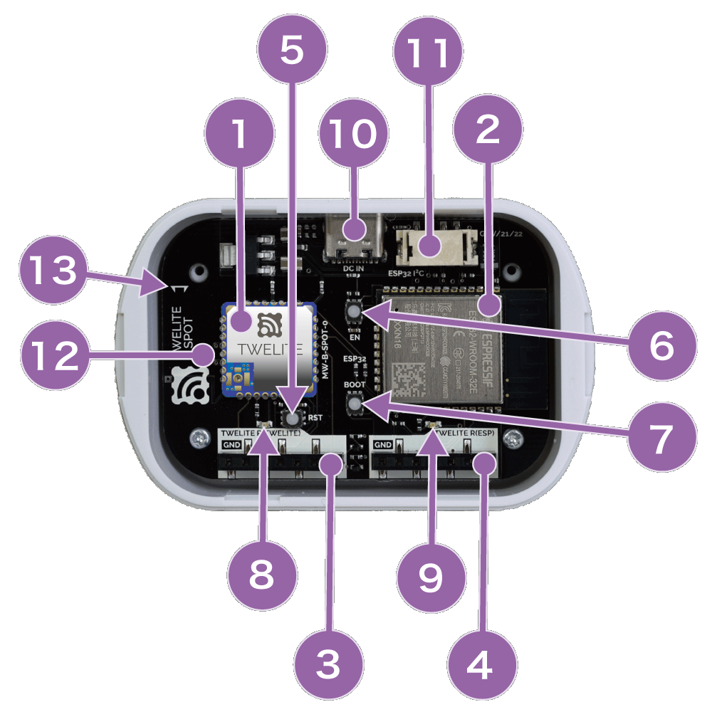
Description of Components
① TWELITE
TWELITE is a wireless microcontroller module used for communication with other TWELITE modules.
② ESP32
Wireless LAN module by Espressif Systems.
③ 7P Interface (TWELITE)
Interface used for updating the TWELITE application. Normally not used.
This is the terminal to connect to TWELITE R3 / R2. Please connect with the correct orientation. Incorrect connection may cause damage.
Power supply is not provided from here. Power is supplied from the USB-C connector.
The following is the signal pin correspondence table:
| Name | Signal Name | TWELITE | Description |
|---|---|---|---|
| GND | GND | 20, 28, 30, 31, 32 | GND |
| TXD | DIO6 | 8 | UART (PC RX) |
| PRG | SPIMISO | 2 | Enter program mode at startup when Low level |
| RXD | DIO7 | 9 | UART (PC TX) |
| RST | RESETN | 21 | Reset at Low level |
| VCC | - | - | Not connected (Power supplied from side) |
| SET | DIO12 | 13 | Extended control signal |
④ 7P Interface (ESP32)
Interface used for writing ESP32 applications. Normally used for firmware development.
This is the terminal to connect to TWELITE R3 / R2. Please connect with the correct orientation. Incorrect connection may cause damage.
Power supply is not provided from here. Power is supplied from the USB-C connector.
The following is the signal pin correspondence table:
| Name | Signal Name | ESP32 | Description |
|---|---|---|---|
| GND | GND | 1, 38 | GND |
| TXD | IO1 | 35 | UART (PC RX) |
| PRG | IO0 | 25 | Enter program mode at startup when Low level |
| RXD | IO3 | 34 | UART (PC TX) |
| RST | EN | 3 | Reset at Low level |
| VCC | - | - | Not connected (Power supplied from side) |
| SET | IO2 | 24 | Extended control signal |
⑤ Reset Switch (TWELITE)
Resets TWELITE.
⑥ Reset Switch (ESP32)
EN switch of ESP32. Resets ESP32.
⑦ Boot Switch (ESP32)
BOOT switch of ESP32.
Pressing this switch while resetting puts ESP32 into programming mode.
⑧ LED (TWELITE)
Status LED for TWELITE.
In the parent/relay app, the LED lights up at startup or when receiving the command from the super-easy! standard app to pull DO1 Low.
⑨ LED (ESP32)
Status LED for ESP32.
In MWings, passing pin number
18 as the second argument to Twelite.begin() lights this LED at startup, on packet reception, and command transmission.⑩ USB-C Connector
Power supply only. No signal lines connected.
⑪ Grove I2C Connector (ESP32)
Connected to ESP32’s I2C port (IO21, 22). Can be used to connect OLED displays, etc.
⑫ TWELITE PCB Antenna
MW-A-P1934 PCB antenna.
TWELITE dedicated 2.4GHz inverted F-type antenna formed by circuit patterns on the board.
⑬ Antenna Direction Mark
Indicates the polarization direction of the antenna.
Please align the antenna direction mark with that of the TWELITE series device you are communicating with as much as possible.
External Dimensions
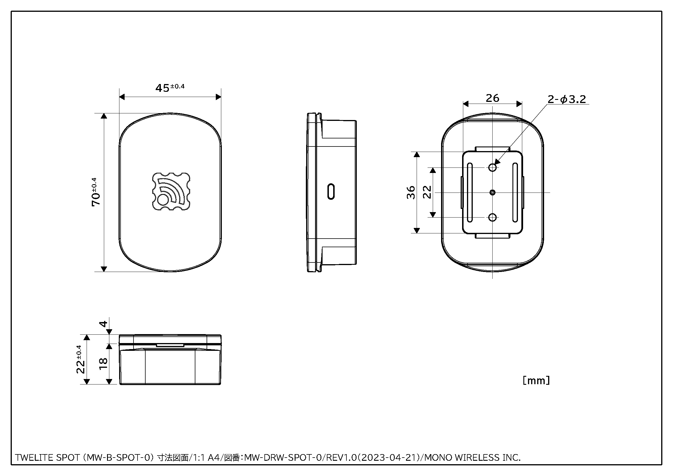
External Dimensions
Download the PDF file here
Use two M3 screws to mount on the wall.
Circuit Diagram
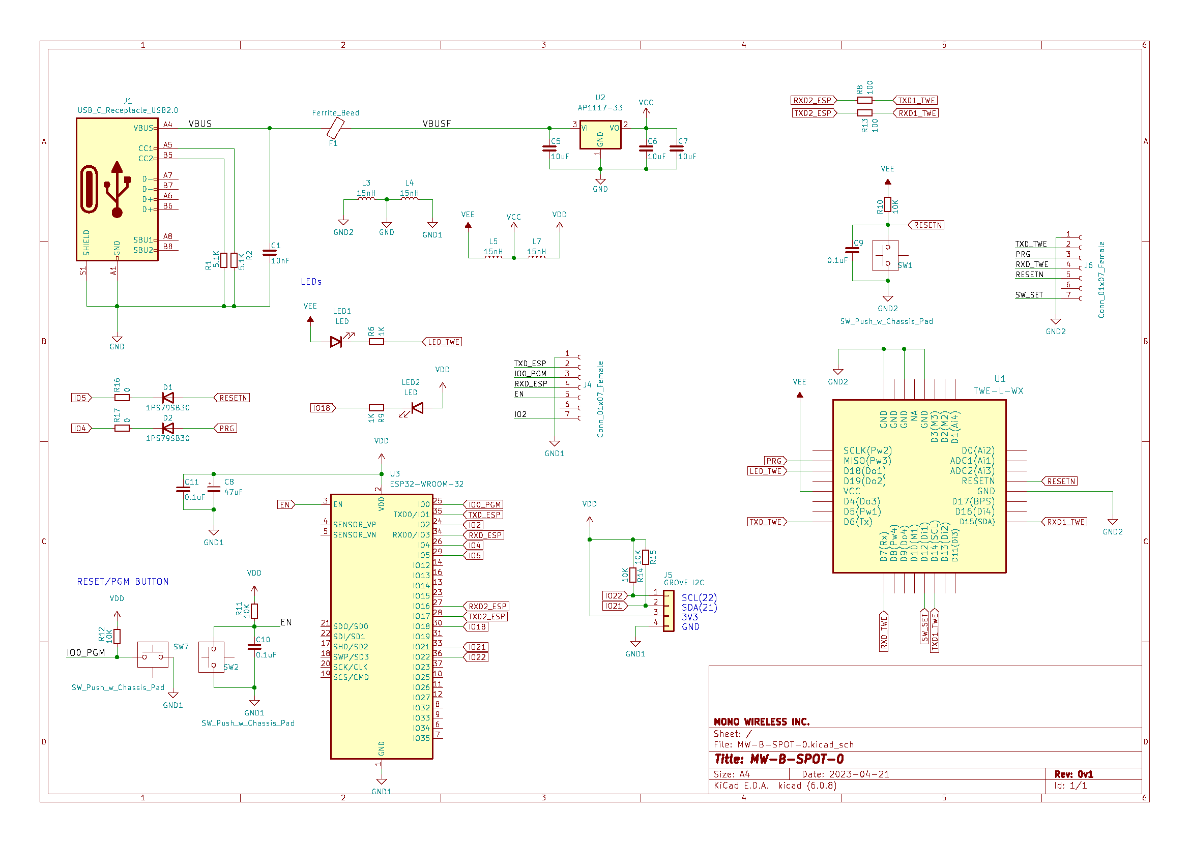
Circuit Diagram
Download the PDF file here
Specifications
Recommended Operating Conditions
| Item | Symbol | Condition | min | typ | max | |
|---|---|---|---|---|---|---|
| Power Supply Voltage | VCC | Compliant with USB spec | 4.5 | 5.0 | 5.5 | V |
| Operating Temperature | TOPR | No condensation | 0 | 60 | °C | |
| Operating Humidity | HOPR | No condensation | 85 | % |
Please refer to the datasheets of individual components for unspecified values.
Precautions
Changing TWELITE Settings
Frequency channels and other settings are changed from the ESP32. Unlike other products, interactive mode cannot be used from the 7P interface. Settings are done using the TWELITE dedicated Arduino library prepared for ESP32.
- The 7P interface on the TWELITE side is only used for updating the SPOT dedicated parent app.
About the 7P Interface
Power supply is not provided from the 7P interface. When connecting TWELITE R series, please supply power from the USB-C connector.
About USB Power Supply
Please use an AC adapter that can supply 5V / 1A or more with low noise.
Connecting to a PC
When rewriting the ESP32 firmware, remove the cover of the TWELITE SPOT and connect the TWELITE R3 / R2 to the 7P interface (side marked ESP) as shown below.
Connect the TWELITE R3 / R2 in the same orientation as shown below. Incorrect connection may damage the TWELITE SPOT or TWELITE R3 / R2.
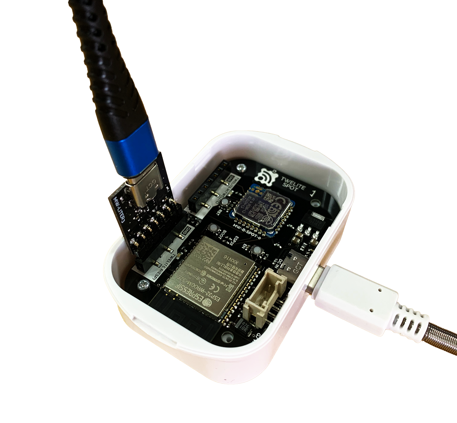
ESP32 Connection
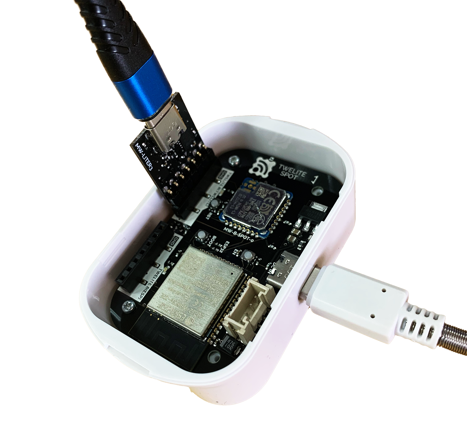
TWELITE Connection
Installation
Please satisfy the following conditions as much as possible.
- Point the antenna direction mark vertically (up/down)
- It is preferable to install with the antenna direction mark facing up, but facing down does not cause significant impact.
- Align the antenna direction mark of TWELITE SPOT and the child device.
- Do not place obstacles between TWELITE SPOT and child devices.
For detailed installation methods of the TWELITE series, please refer to the Installation Guide - For Good Communication.
Disposal
When disposing of this device, please follow the ordinances and regulations of your local government. For details, please contact your local government.
Revision History
| Version | Date | Summary |
|---|---|---|
| 1.0.1 | 2023/06/14 | Added Precautions |
| 1.0.0 | 2023/05/15 | Initial Version |