A TWELITE module with a 7P interface, specialized for serial communication.
This is the multi-page printable view of this section. Click here to print...
For suitable output, we recommend to use Google Chrome (15+) or Microsoft Edge (79+).
TWELITE UART Datasheet
TWELITE module specialized for serial communication
1 - TWELITE UART (BLUE / RED) Datasheet
Model: MW-(B/R)-UART-(P/U)
TWELITE UART (BLUE / RED) is a wireless module equipped with a 7P interface.
1.1 - TWELITE UART (BLUE / RED) Datasheet
Latest Edition
TWELITE UART is ideal for connecting to external microcontrollers via UART. It implements a 7P interface that includes TX, RX, VCC, and GND.
The Serial Communication App (App_Uart) is pre-installed, allowing immediate wireless communication with microcontrollers, etc., simply by wiring.
Users can also edit and rewrite the application (firmware) themselves.
Specifications
Product Model
The model numbers of TWELITE UART are as follows.
| Common Name | Sales Code | Remarks |
|---|---|---|
| TWELITE UART (BLUE) | MW-B-UART-P | Standard Output, Built-in Antenna |
| MW-B-UART-U | Standard Output, Coaxial Connector | |
| TWELITE UART (RED) | MW-R-UART-P | High Output, Built-in Antenna |
| MW-R-UART-U | High Output, Coaxial Connector |
Sales codes are subject to change. Please refer to our website for the latest information.
Radio / Microcontroller
For specifications of the radio and microcontroller sections, please refer to the TWELITE Datasheet.
Each TWELITE UART includes the following TWELITE module:
| Model Number | Included TWELITE |
|---|---|
| MW-B-UART-P | TWE-L-WX |
| MW-B-UART-U | TWE-L-U |
| MW-R-UART-P | MW-R-WX |
| MW-R-UART-U | MW-R-U |
Antenna
The following data is for models with internal antennas (MW-(B/R)-UART-P).
For models with external antennas (MW-(B/R)-UART-U), please refer to the antenna datasheet.
| Item | Specification |
|---|---|
| Antenna Type | MW-A-P1934 (Datasheet) |
| Gain (Typical Omnidirectional Plane) | 1.4[dBi] |
| Polarization | Linear Polarization |
Vertical Directional Pattern
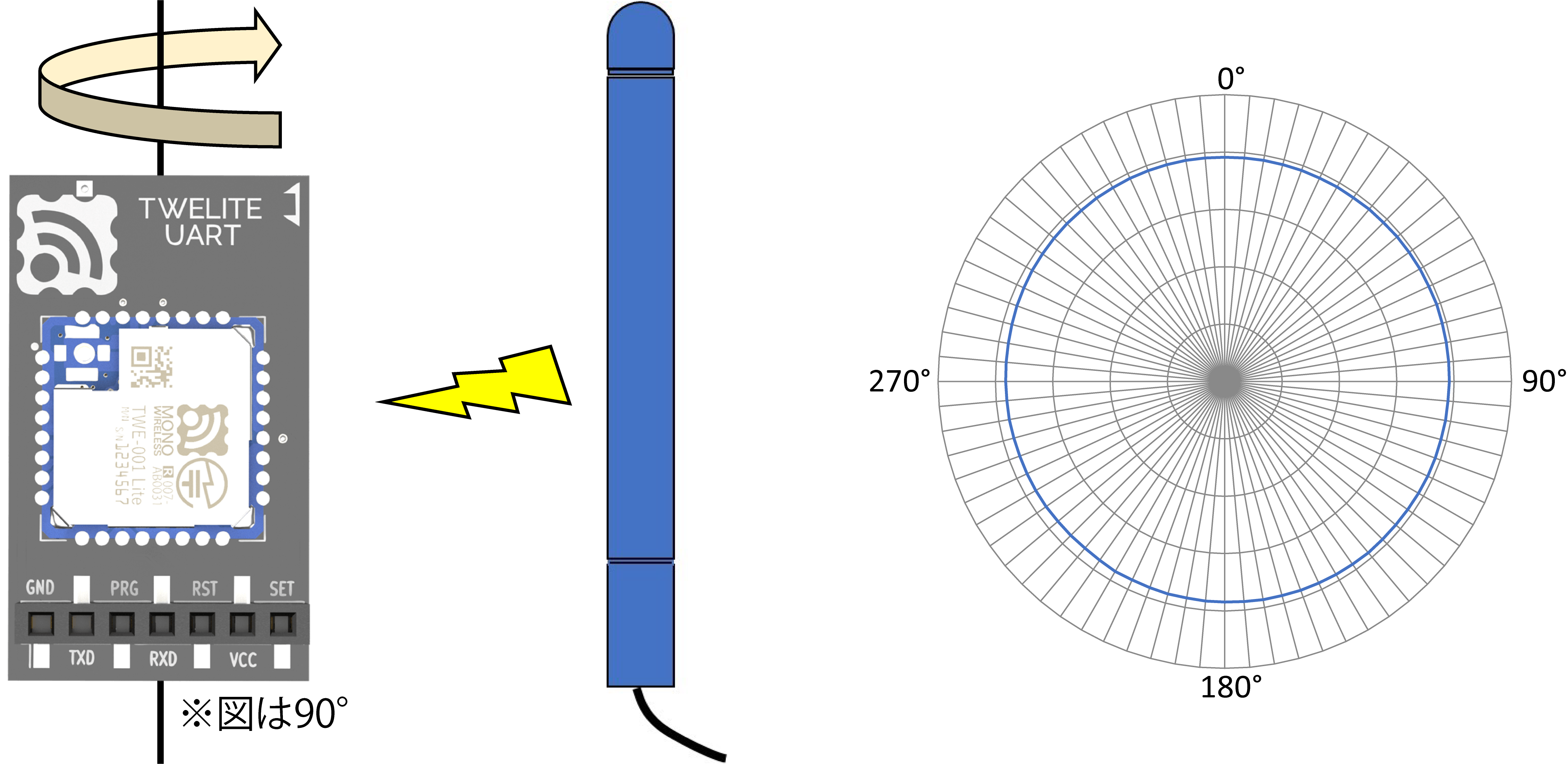
Vertical Directional Pattern
Horizontal Directional Pattern
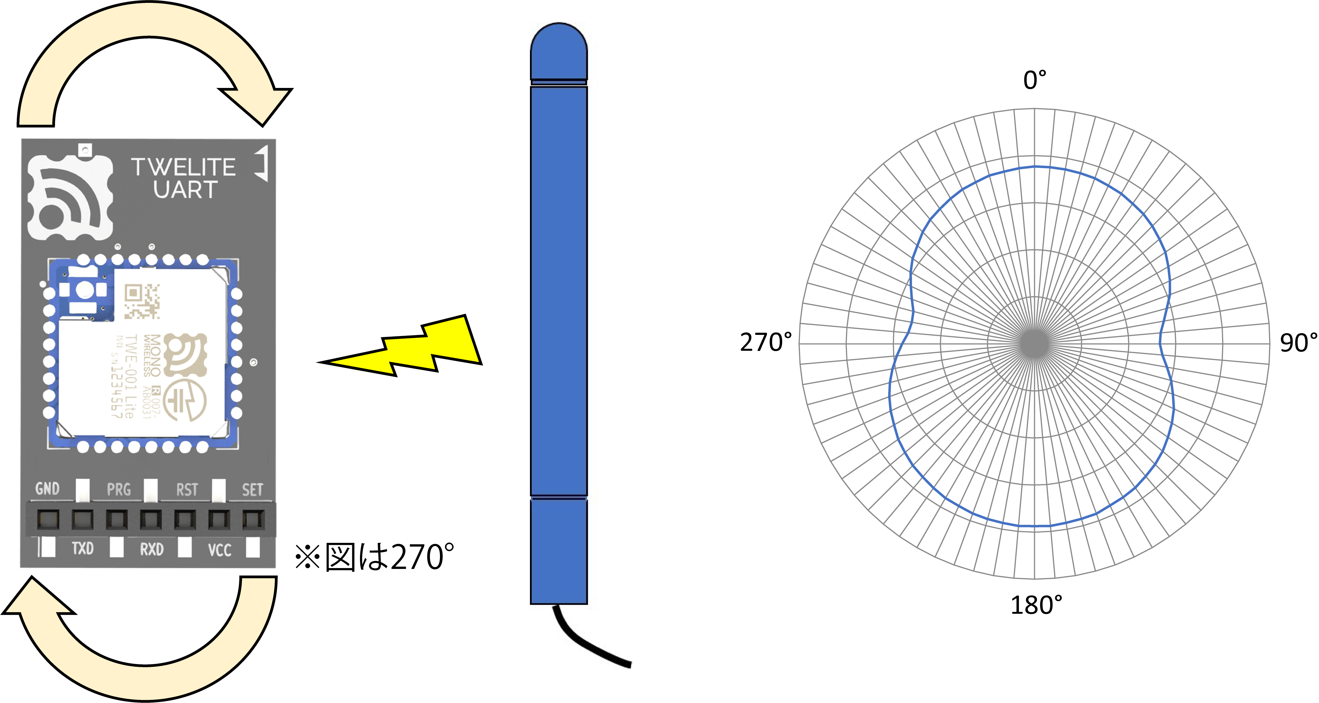
Horizontal Directional Pattern
Certifications
| MW-B-UART-(P/U) | MW-R-UART-(P/U) | |
|---|---|---|
| Certification Model | TWE-001 Lite | TWELITE RED |
| Construction Design Certification Number | 007-AB0031 | 007-AF0062 |
| FCC ID | 2AINN-L1 | - |
| IC ID | 21544-L1 | - |
| Remarks | RoHS Compliant | RoHS Compliant |
Only MW-B-UART-(P/U) models are approved for overseas use.
Depending on the country of use, labeling such as FCC ID or IC ID may be required on the TWELITE or the product. Please contact us if you believe this applies.
Dimensions
MW-(B/R)-UART-P
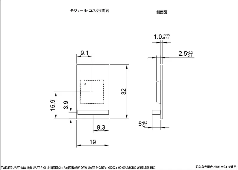
Dimensions for Antenna Type
MW-(B/R)-UART-U
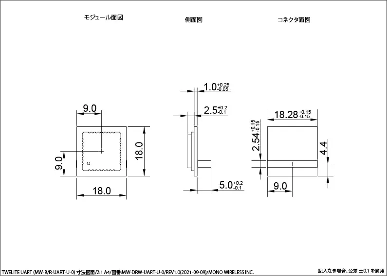
Dimensions for Coaxial Connector Type
Circuit Diagram
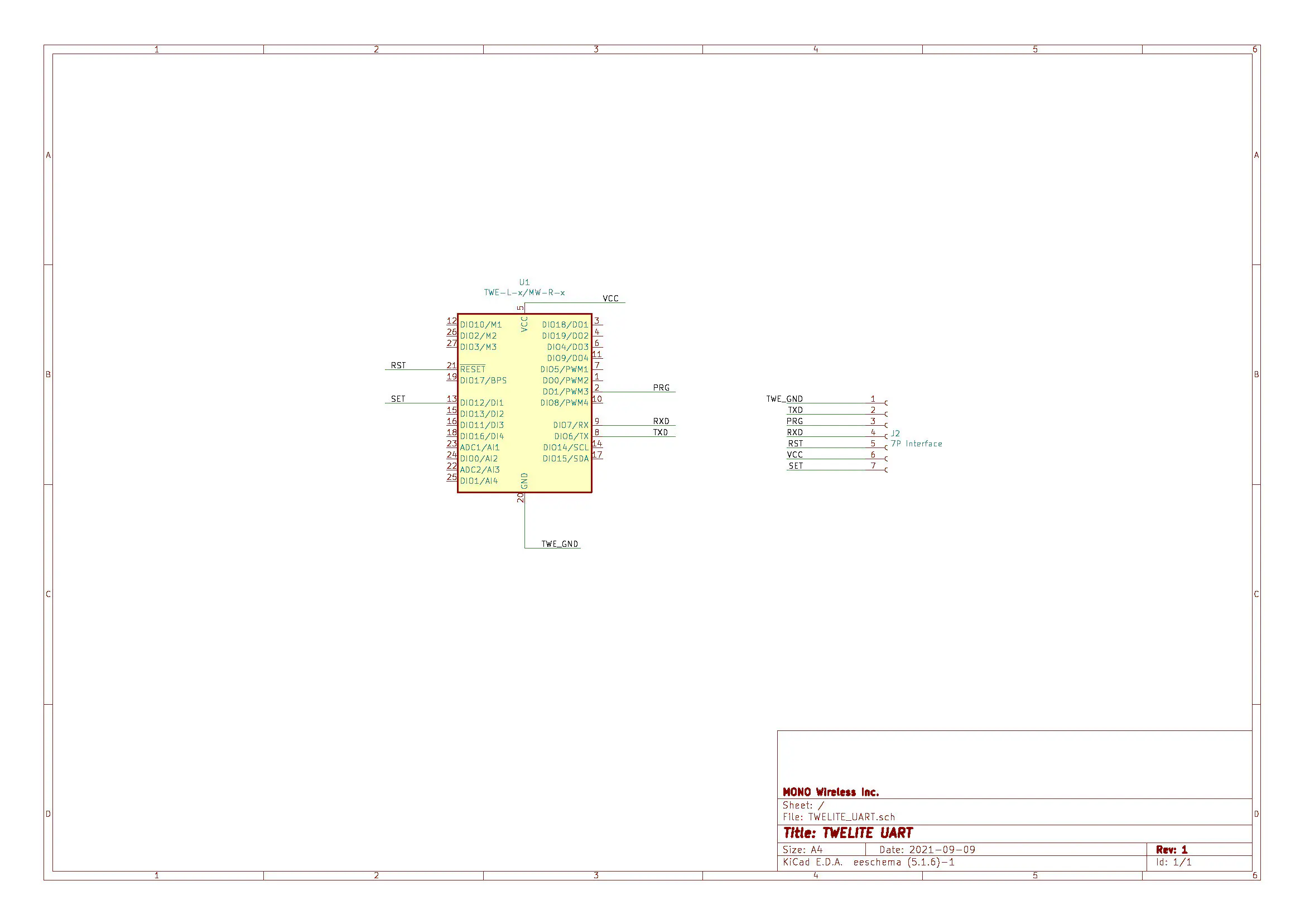
Circuit Diagram
Characteristics
The following characteristics are specific to TWELITE UART or derived from component datasheets.
For unspecified values, please refer to the respective datasheets.
Values are based on semiconductor datasheets.
TWELITE
For details, please refer to the TWELITE Datasheet.
Absolute Maximum Ratings
| Parameter | Min | Max | Unit |
|---|---|---|---|
| Power Supply (VCC) | -0.3 | 3.6 | V |
| Analog IO (VREF/ADC) | -0.3 | VCC+0.3 | V |
| Digital IO | -0.3 | VCC+0.3 | V |
Recommended Operating Conditions
| Parameter | Condition | Min | Typ | Max | Unit |
|---|---|---|---|---|---|
| Supply Voltage | 2.0 | 3.0 | 3.6 | V | |
| Start Voltage | 2.05 | V | |||
| Operating Temperature | No condensation | -20 | 75 | °C | |
| Operating Humidity | No condensation | 85 | %RH |
Current Consumption
| Condition | Min | Typ | Max | Unit |
|---|---|---|---|---|
| Sleep (RAMOFF, no timer) | 0.1 | uA | ||
| Sleep (RAMON, with timer) | 1.5 | uA | ||
| Tx (CPU doze) MW-B-UART-(P/U) | 15.3 | mA | ||
| Tx (CPU doze) MW-R-UART-(P/U) | 23.3 | mA | ||
| Rx (CPU doze) MW-B-UART-(P/U) | 17.0 | mA | ||
| Rx (CPU doze) MW-R-UART-(P/U) | 14.0 | mA |
I/O Characteristics
| Parameter | Condition | Min | Typ | Max | Unit |
|---|---|---|---|---|---|
| DIO Internal Pull-up | 40 | 50 | 60 | kΩ | |
| DIO High Input | VCC×0.7 | VCC | V | ||
| DIO Low Input | -0.3 | VCC×0.27 | V | ||
| DIO Input Hysteresis | 200 | 310 | 400 | mV | |
| DIO High Output | VCC×0.8 | VCC | V | ||
| DIO Low Output | 0 | 0.4 | V | ||
| DIO Load, Sink Current | VCC 2.7~3.6V | 4 | mA | ||
| VCC 2.2~2.7V | 3 | mA | |||
| VCC 2.0~2.2V | 2.5 | mA |
Precautions
Wiring Precautions
Inputting signals that do not meet I/O characteristics may damage the product.
For example, microcontrollers operating at 5V cannot be connected directly. Please use voltage level conversion (level shifting).
Also, RS232C cannot be connected directly due to different operating voltages. Use a signal converter between RS232C and UART.
General Notes
Please always evaluate and verify the product in your own usage environment.
For applications requiring high reliability or related to human life, please consult your distributor in advance.
Revision History
| Version | Date | Details |
|---|---|---|
| 1.0.2 | 2024/3/15 | Added examples to Wiring Precautions |
| 1.0.1 | 2024/2/27 | Migrated to new site; minor corrections |
| 1.0.0 | 2021/9/9 | Initial Version |