This section summarizes frequently asked questions regarding technical information about TWELITE.
For initial product defects and similar issues, please contact the retailer from whom you purchased the product.
If the problem is not resolved, please contact the Support Desk.
1 - General Questions about the TWELITE Series
Questions regarding the TWELITE Series in general
This page summarizes frequently asked questions about the TWELITE Series in general.
General
What applications is TWELITE suitable for?
TWELITE is specialized for efficiently transmitting data up to several dozen bytes, such as sensor measurements.
Unlike Bluetooth or Zigbee, TWELITE does not establish a connection; it communicates in broadcast mode by matching the frequency channel like a transceiver. This allows you to start transmitting immediately after powering on. You can also create a transmit-only device for ultra-low power operation by not performing any power-consuming receive processing.
The IEEE 802.15.4 packets used by TWELITE have a maximum size of 128 bytes. However, only several dozen bytes are available for data due to auxiliary information (for example, Serial Communication App allows 80 bytes).
What applications is TWELITE not suitable for?
For continuous data transmission exceeding several dozen bytes, such as images or audio, Bluetooth or Wi-Fi is more suitable than TWELITE.
When sending continuous data, you need to split the data into packets with TWELITE. If some of these split packets are lost, you must handle the missing data, so protocols like Bluetooth or Wi-Fi that establish a connection before sending data are more appropriate.
For long-distance transmission of large continuous data like images in locations without access points, standards that support high-speed communication such as LTE-m are more suitable. In recent years, satellite communication may also be an option.
Hardware
What is the difference between the BLUE and RED Series?
Basically, the only difference is the transmit output power.
They can communicate with each other. The receive performance is almost the same for both.
What semiconductor is mounted on the TWELITE Series?
The operating voltage of the TWELITE main unit is 3.3V (2.0-3.6V), and the current consumption is as stated in the data sheet:
Maximum during transmission: 15.3mA (BLUE) / 23.3mA (RED)
Maximum during reception: 17.0mA (BLUE) / 14.7mA (RED)
Normal sleep: 1.5uA (BLUE/RED)
In practice, the power consumption of sensors and other devices is added, and it is also affected by whether you use the TWELITE’s wireless reception function and how frequently you transmit.
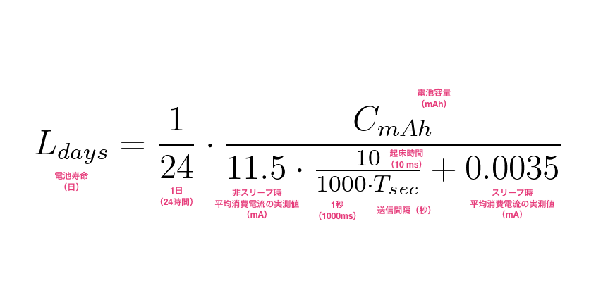
For example, TWELITE ARIA can operate with a CR2032 coin cell by operating as transmit-only. Assuming a CR2032 coin cell capacity of 220mAh and a transmission interval of 5 seconds, you can achieve about one year of battery life.
What is the connector type for the coaxial connector type?
The coaxial connector (u.FL) mounted on modules of the coaxial connector type is I-PEX 20441-001E-01. The 4pads type is adopted to suppress misalignment during mounting.
Can I use the module without connecting an antenna to the coaxial connector?
If you do not connect an antenna to the coaxial connector, communication performance will be significantly reduced.
In general, communication may be possible within about 1 meter, but communication over several meters is difficult.
However, the construction design certification includes the state with no antenna connected, so there is no legal issue.
What happens with unconnected input/output pins?
Normally, unconnected input/output pins are pulled up internally by a resistor (about 50kΩ) inside the semiconductor.
Is the output push-pull?
Yes.
How much current can be drawn from the output pin?
As stated in the data sheet, the maximum is 4mA (when the supply voltage is 2.7-3.6V).
Is a capacitor required when connecting a switch to the reset pin?
It is not required, but you may install one if you wish.
What are the requirements for electrical reset?
For reset operation, provide a pulse width of at least 1us.
Startup usually takes 180us (communication starts after initialization processing).
For details, refer to the data sheet of the mounted semiconductor.
Normally, there is no problem with hardware performance.
We cannot guarantee legal interpretations, but we have heard that there is generally no problem if the technical conformity mark cannot be confirmed due to potting.
How many times can the built-in flash memory be written?
At least 100,000 times, typically 1,000,000 times.
Is an RTC (real-time clock) included?
There is no real-time clock function on the main unit.
Is there 3DCAD data for the product?
No, unfortunately not.
The rendered images on the web page are created using 3DCG software and cannot be used for design.
What are the dot-like patterns that appear on the surface of the main unit’s shield can?
Discoloration may be seen when the oxide film on the surface is scratched, similar to stainless steel bowls or pans.
Wireless Communication
What frequency band does it use?
2.4GHz.
Can I change the channel?
You can use all 16 channels from 11 (2405MHz) to 26 (2480MHz) (in Japan).
Is it Zigbee compatible?
It is not Zigbee compliant.
While TWELITE conforms to the IEEE 802.15.4 standard like Zigbee, it uses its own simple and easy-to-use TWELITE NET protocol stack on the upper layers, not the Zigbee protocol stack.
Are there any license fees like Bluetooth?
No. When selling products equipped with TWELITE, you do not need our permission or to purchase a license.
What is the communication range?
It is greatly affected by the surrounding environment, settings, installation location, and antenna type, so it is difficult to give a definitive answer.
In some cases it may be 10m, in others up to 1km. Unfortunately, you will need to try it in your actual environment to confirm.
As a general guideline, in typical urban areas with a clear line of sight, the communication distance may be about 100m for the BLUE series and about 200m for the RED series.
In our reinforced concrete office, we have achieved about 20m even through 1–2 walls (using a high-output RED series on the transmitting side).
What is the maximum number of simultaneous connections?
Basically, TWELITE does not establish connections and communicates in broadcast mode like a transceiver. Therefore, there is no logically defined maximum number of connections, and you can increase the number of devices as long as they do not physically interfere.
However, with existing firmware like the “Extremely Simple! Standard App” (App_Twelite), the maximum logical device ID for Child devices is 100. Also, if the transmission interval of transmitters is short, the number of usable devices decreases. As a guideline, if the transmission interval is T seconds, we recommend about T/0.1 as the maximum number of transmitters (about T/0.4 when using Repeaters).
Countermeasures for transmission interference and transmission intervals
In firmware such as TWELITE CUE and ARIA, the actual transmission interval is randomized within ±10% of the set value to prevent all devices from transmitting at exactly the same timing. Also, the IEEE 802.15.4 layer that handles packet transmission and reception has a carrier sense function to help avoid transmission interference.
The time required to transmit a single packet is about 5–6ms. However, since retransmitting two or more times is generally recommended, it takes at least about 15ms. The recommended minimum transmission interval of 100ms above is set with a margin for reliability.
What is the practical communication speed?
Assuming one-to-one communication and ideal conditions with highly optimized firmware, the speed is about 40kbps.
It takes about 5.3ms from when one TWELITE processes a packet transmission request to when the other TWELITE processes the received packet data.
The maximum data that can fit in one packet is about 80 bytes (for the Serial Communication App).
For practical reliability, it is generally recommended to retransmit packets at least twice (i.e., transmit each packet three times in total). Therefore, it takes about 16ms to transmit one packet, resulting in a practical speed of approximately 1000/16*80*8 = 40000 = 40kbps.
How can I avoid interference with Wi-Fi?
Wi-Fi and IEEE 802.15.4 both use the 2.4GHz band, so radio interference can occasionally occur. If you can change the frequency channel on the Wi-Fi side, set the TWELITE frequency channel as far apart as possible from Wi-Fi.
Reference material
For details on channel relationships and interference countermeasures, the semiconductor manufacturer provides the following document:
Any device using the 2.4GHz ISM band may cause interference, including:
TWELITE devices set to the same frequency channel
Wi-Fi (IEEE 802.11.b/g/n) routers, PCs, smartphones, and similar devices
Bluetooth input devices, sensors, etc.
Smart home devices using Thread/Matter (Zigbee-based)
Xbee (especially S1)
2.4GHz wireless microphones
Mouse or keyboard receivers (e.g., Unifying receivers)
Microwave ovens and other products using microwaves located nearby
Devices such as 5GHz Wi-Fi equipment, low-power transceivers (400MHz), and LoRaWAN devices (920MHz) are not affected, but many communication devices can cause interference.
However, since the time required to send or receive a single packet is only a few milliseconds, the simple communication method means that as long as the channel is briefly available, communication may succeed. Obstacles such as walls, ceilings, metal machinery, or noise generated by them often have a greater impact on communication than interference from other wireless devices.
Is it impossible to communicate at exhibition venues?
Exhibition venues (for electronics) are among the harshest communication environments we know.
At exhibition venues, the 2.4GHz band is flooded with an extraordinary amount of noise. TWELITE, which does not have frequency hopping, may sometimes work when Bluetooth and other devices cannot, but basically, all devices may become unable to communicate.
When we exhibit, we either use a simple RF shield box for demonstrations or show video demonstrations instead.
Is there wireless packet compatibility between series?
Yes, there is compatibility. For example, a packet sent by a TWELITE BLUE can be received by a TWELITE RED.
What is the typical amount of energy required for a single transmission?
Regardless of the supply voltage, at least about 100uC of electric charge is required per transmission.
Can the device wake from sleep upon packet reception?
No, it cannot. To receive a packet, the CPU must be awake and the receiver circuit must be enabled.
Can Repeaters operate intermittently?
No, they cannot. Repeaters must operate continuously to wait for incoming packets.
Repeaters require a power supply that can always provide at least about 20mA of current. Power sources such as TWE-EH SOLAR or CR2032 coin cell batteries cannot drive Repeaters.
Why is received data output only once when using a Repeater?
The Parent discards any duplicate packets it receives, keeping only the first one. Therefore, data output is limited to a single occurrence per packet.
How can I verify that repeating is working?
In a Simple Network, you cannot determine from the data itself whether a packet was relayed by a specific Repeater.
Simple method using a microwave oven
A microwave oven, which uses microwaves, can function as a simple RF shield box.
Place the transmitter inside the microwave and close the lid, press the Repeater against the microwave, and keep the receiver at a distance. This creates a situation where communication cannot succeed without relying on the Repeater. If communication stops when the Repeater is turned off, you can confirm that the Repeater is functioning as expected.
Is it always better to add more Repeaters?
No.
Since the communication method does not use routing, adding too many Repeaters can greatly increase the number of packets on the network, reducing reliability. When using Repeaters, we recommend gradually increasing the number of devices with repeating functionality to find the optimal configuration.
Can the number of repeating hops be increased to more than three?
It is possible to increase the number of repeat hops by modifying the TWELITE firmware, but this is not recommended as it can lead to an excessive number of packets. For long-distance communication, using an existing network is generally preferable.
How to connect to a LAN
For example, by using TWELITE SPOT and a wireless LAN router, you can send data received by a TWELITE Parent to a LAN.
Alternatively, although this tends to increase power consumption, you can insert a USB-type MONOSTICK into a small PC such as a Raspberry Pi and send the received data to the LAN.
While some work may be required, it is technically possible
Packets sent by Child devices in the TWELITE series can be received not only by MONOSTICK, but also by products such as TWELITE DIP or TWELITE UART with Parent or Repeater firmware (App_Wings) written.
Devices that receive packets convert the received data to a hexadecimal string and output it via UART communication at 115200bps, 8-N-1. (See output details)
The TWELITE STAGE app on your PC simply interprets these strings to display the data. UART communication is compatible with RS-232C except for the voltage level.
Therefore, by using a commercially available UART (3.3V) / RS-232C conversion module to convert the voltage level of the Parent’s output, it should be possible to connect to the serial communication unit of a PLC.
However, you will need to implement a mechanism in the serial communication unit to interpret the Parent’s output strings.
Configuration
When using multiple Child devices with one Parent, is it sufficient to change only the logical device ID of each Child?
Yes.
How should I configure settings when using multiple groups of Parents and Children at the same time?
Assign a different frequency channel and Application ID to each group.
The frequency channel separates networks physically, while the Application ID separates them logically. The maximum number of groups separated by channel is 16. If the frequency channel is the same, data from devices with different Application IDs will not be received, but the packets themselves may still interfere with each other.
What does the retransmission count in Interactive Mode mean?
In a Simple Network, the retransmission count refers to the number of additional packets sent when transmitting a packet.
For example, if you set the retransmission count to 3, the packet will actually be sent 4 times in total.
Set an appropriate retransmission count if the transmission interval allows
If you do not use retransmissions, even in ideal communication environments, about 10% of packets are empirically lost.
Assuming a 10% packet loss rate with zero retransmissions, the theoretical packet loss rate with two retransmissions is 0.1^3=0.001, so 99.9% of packets should be delivered reliably.
Increasing the retransmission count improves reliability, but setting it too high can increase channel occupancy time and power consumption. If your transmission interval allows (several seconds or more), we recommend setting the retransmission count to 2 or 3.
If you want to always obtain the latest data continuously, such as when implementing a remote control, it is generally better to set the retransmission count to zero and shorten the transmission interval, rather than increasing the retransmission count.
In the case of a Repeater Network
In a Repeater Network, the retransmission count indicates the maximum number of additional packets sent when an ACK from the MAC layer cannot be confirmed.
Does the transmit power setting affect the receiving side as well?
How can I improve the reliability of transmission and reception?
In addition to setting an appropriate retransmission count (see above), you can further improve reliability by retransmitting packets at different times.
The more times you transmit, the higher the chance of successful delivery. However, simply increasing the retransmission count may not prevent packet loss due to temporary noise or obstacles.
By implementing a mechanism that stores packets in a queue and retransmits them after a certain amount of time has passed, you can reduce the impact of temporary noise or obstacles.
Certification, Authorization, and Export Regulations
Can I use a third-party antenna with TWELITE?
Please contact us. If the antenna is already listed on our official antenna list, you may be able to use it immediately.
Do I need to obtain certification when integrating TWELITE into an enclosure?
The TWELITE Series has already obtained technical conformity certification (construction design certification). You do not need to obtain certification yourself. However, you must ensure that the technical conformity mark is visible.
You must use either our dedicated TWELITE Series antenna or the designated antenna pattern.
Must the technical conformity mark be displayed when integrating into an enclosure?
For products incorporating a TWELITE module that has received construction design certification, you may display the technical conformity mark using the registration number of the TWELITE module.
For the TWELITE BLUE Series, enter Grantee Code 2AINN.
Is certification required when using overseas?
Please contact us. The requirements vary by country and region.
① Countries or regions where certification of standalone wireless modules is recognized
In countries and regions like Japan, the United States, and Canada, where certification of the wireless module itself is recognized, you can use TWELITE without performing certification procedures as long as you meet the usage conditions.
Only TWELITE BLUE supports the United States (FCC) and Canada (ISED/IC) (Single Modular Approval applies only to pattern and wire antennas; u.FL connector types are not supported for any series).
② Countries or regions where certification of some wireless modules is optional
In countries and regions such as China, Hong Kong, and Vietnam, where certification of short-range communication devices is optional if certain conditions are met, it may be possible to use TWELITE without certification procedures.
If using indicators such as EIRP or ERP, please pay attention to combinations of the main unit (especially the RED Series) and high-gain antennas (such as MW-A-BP01), as well as output settings.
③ Countries or regions that require certification for the final product
In most countries and regions, certification is required for the final product incorporating the wireless module. In other words, certification of the wireless module alone is not meaningful, and you will be required to prepare a new report for your product.
A typical example is the CE regulation in Europe. CE applies to the final product, so you need to create an EN report for the entire product.
In countries and regions outside Europe and the US, such as Southeast Asia, it is sometimes possible to use CE documentation prepared for Europe for certification procedures.
MONOSTICK BLUE is compliant with CE regulations as a final product.
Can the TWELITE RED Series be used overseas?
In most cases, the TWELITE RED Series does not meet overseas regulatory requirements.
Background on why we do not support FCC or CE for RED Series
Due to increased transmission output, spurious emissions—especially harmonics in the 5GHz and 7GHz bands—increase, making it difficult to meet emission regulations in many countries.
However, in some countries or regions where certification of wireless modules is optional, it may be possible to use the RED Series.
How is export control classification determined?
We cannot guarantee the validity of interpretations regarding legal regulations.
If you wish to obtain a parameter sheet prepared by us, please contact us. We consider TWELITE wireless modules and products incorporating them as subject to export control due to the inclusion of AES encryption circuits.
Are there exceptions or exemptions?
Since TWELITE wireless modules are developer parts that support firmware write, our interpretation regarding export exemptions for encryption products is as follows:
Cryptographic special notification: Since the way cryptographic keys and encryption are used can be “changed by the user (by designing and writing firmware),” this special exemption does not apply.
Free-of-charge exemption: Whether this applies is up to the customer’s judgment.
Small-quantity exemption: Whether this applies is up to the customer’s judgment.
We are not in a position to answer questions or requests for interpretation regarding exemptions.
What about final products incorporating the TWELITE Series?
Since TWELITE wireless modules are components, the determination of export control classification and applicability of exemptions for final products incorporating them is the responsibility of the customer.
Is there a wireless module without encryption functionality?
No, there is not.
What does RoHS compliance refer to?
It refers to (EU)2015/863 covering 10 substances.
Is it REACH compliant?
No, it is not.
Is it chemSHERPA compliant?
No, it is not, and there are no plans to comply.
Is it compliant with export regulations for country X?
Please contact usafter confirming that our product is subject to regulation.
In recent years, we have seen trading companies inquire about export regulations unrelated to our products. Please be sure to confirm the relevant CN Code, etc., and provide evidence that an investigation by us is necessary when making such a request.
Can you issue shipping inspection certificates or pass/fail certificates for products?
As a general rule, we do not issue such certificates.
Can you guarantee that software such as the TWELITE STAGE app does not infringe intellectual property?
We cannot guarantee this.
The TWELITE STAGE app and other software utilize numerous open-source software developed by an unspecified number of volunteers. As such software is ported and modified, it is fundamentally impossible to guarantee freedom from intellectual property infringement.
There is no binary file compatibility between the TWELITE BLUE and RED series.
For example, you can write a firmware binary file developed for TWELITE UART BLUE to TWELITE DIP BLUE, but you cannot write it to TWELITE DIP RED.
Can you customize firmware?
As a general rule, we do not accept customization requests.
Implementation
Is there a use-by date?
Some product data sheets may state: “Use the product within six months after delivery.” However, this note is intended for cases where a large number of solder-required products are purchased and kept in a warehouse. For prototypes and DIY projects, there is no need to be particularly concerned.
Software
How can I display Child device data as a graph?
For example, you can use the following approaches:
Local Usage
If you are receiving data with a MONOSTICK connected to a PC and want to display it directly:
You cannot develop firmware for TWELITE using Python.
The TWELITE main unit does not have the capability to run MicroPython or CircuitPython. Firmware development requires Arduino-style C++. For more, see Firmware Development.
However, we provide the MWings Python module for interpreting received data or composing data to be sent on a PC, Mac, or Raspberry Pi connected to MONOSTICK and similar devices (usage example).
PC / Mac:
pip install mwings
Raspberry Pi:
pip install mwingslite
The latter does not depend on numpy, omitting those features for lightweight operation.
Can you develop firmware on my behalf?
Regardless of project size, we do not accept requests for firmware development outsourcing.
Can you introduce a firmware development company?
Regardless of project size, we do not provide referrals to development companies.
If you contact a company specializing in bare-metal embedded software development in C/C++, they should be able to handle TWELITE firmware development.
Bare-metal embedded software development refers to firmware development for microcontrollers such as PIC, AVR, RX, RA, STM32, or LPC.
However, devices such as the TWELITE CUE that involve sleep modes perform a reset with the SET pin held low to wake the device before settings are applied.
What should I do if the device overheats during use, stops working, or fails?
It is possible that the device is affected by static electricity or electromagnetic noise.
Except for the radio section, TWELITE’s basic I/O pins are directly connected to semiconductors. Therefore, in environments with significant static electricity or electromagnetic noise, failure may occur without proper countermeasures.
Please take necessary measures such as enclosing everything except the antenna in a metal case or inserting a 3.6V Zener diode. Please note that we do not provide support for individual cases related to noise countermeasures.
Can it be reflowed twice?
No, it cannot.
Since the semiconductor chips are reflowed onto the board once during TWELITE manufacturing, the reflow count for the TWELITE module is one time only.
3 - TWELITE DIP
Questions about the TWELITE DIP series
This page summarizes questions related to the TWELITE DIP series.
About TWELITE DIP
How to check if it is malfunctioning?
If you can write the firmware, it is possible that it is not malfunctioning; however, if you cannot write the firmware, it is definitely malfunctioning. Please connect to a PC using TWELITE R/R2 and try rewriting the app from the TWELITE STAGE APP.
Select an item starting with App_Twelite_BLUE or App_Twelite_RED and perform the write
(If the write is successful) Open 3: Interactive Mode and confirm that settings can be changed
When you cannot enter Interactive Mode
Interactive Mode uses UART, so settings related to UART may cause it to be unusable. Try initializing the settings with the BPS and AI2 pins left open.
Complete initialization of settings can be done by the following steps:
Write a different TWELITE APP once
Access the Interactive Mode of the different TWELITE APP
Enter R → S to initialize the settings
Write back the original app
By following these steps, you can completely initialize the settings stored in non-volatile memory.
Hardware
Are there recommended pin sockets?
The pin headers of TWELITE DIP BLUE/RED are so-called fine pin headers with a 0.5mm pitch. Therefore, you can use any pin socket compatible with 0.5mm pitch pin headers.
For terminals such as TWELITE CUE that involve sleep mode, communication will not work unless the SET pin is connected. This is because the SET pin is held at a low level during reset to disable sleep before configuration.
Has the board design been changed?
Starting from production in June 2024, the board design has been changed. The 600mil DIP form factor remains unchanged, but the appearance and slight dimensions have been modified, and the pin insertion holes and antenna mounting openings have been slightly expanded.
Firmware writing and wireless communication can be performed as with previous products.
Is it compatible with TWE-Lite Dip sold by Tokyo Cosmos Electric?
TWELITE DIP (BLUE series) is compatible with the TWE-Lite Dip previously sold by Tokyo Cosmos Electric.
However, the firmware version installed at shipment has been updated, and the design changes mentioned above have been applied. Firmware writing and wireless communication can be performed as with that product.
Remote Control App
How to resolve the issue where communication between Parent and Child fails when set to intermittent mode?
Try pulling up the C1/C2 (#23/#25) pins (or connecting them to VCC), or disable these pins. In intermittent mode, these pins are not internally pulled up, which may cause unexpected behavior.
Others
Has the flat matchstick antenna type been discontinued?
Yes. The flat matchstick antenna type TWELITE DIP PCB TWE-L-D(I/P)-P was discontinued in 2019. As a replacement, please consider the combination of the coaxial connector connection type TWE-L-DI-U and the thin antenna MW-A-P2010.
4 - MONOSTICK
Questions about the MONOSTICK series
This page summarizes questions related to the MONOSTICK series.
No. It must operate continuously to wait for received packets.
The Repeater requires a power supply that can always provide about 20mA or more current. Power sources such as TWE-EH SOLAR or CR2032 button batteries cannot power the Repeater.
Why is the received data output only once when using the Repeater?
When the Parent receives the same packet multiple times, it discards the later receptions. Therefore, data output is limited to once.
How can I verify the operation of the Repeater?
In a simple network, it is not possible to confirm from the data whether a packet was relayed by a specific Repeater.
Simple verification method using a microwave oven
A microwave oven acts as a simple radio shield.
Place the transmitter inside the microwave oven and close the door, place the Repeater in close contact with the microwave oven, and keep the receiver away. This creates a situation where communication can only succeed by relying on the Repeater. If communication stops when the Repeater is turned off, it confirms that the Repeater is operating as expected.
Is it better to increase the number of Repeaters?
No.
Because the communication method does not perform routing, having too many Repeaters greatly increases the number of packets, which can actually reduce reliability. When using Repeaters, it is recommended to gradually increase the number of devices with Repeater functionality and find the optimal configuration.
How can I increase the number of relay hops to 3 or more?
It is possible to increase the number of relay hops by modifying the TWELITE firmware, but this is not recommended due to a significant increase in the number of packets. For long-distance communication, it is better to use an existing network.
How to connect to LAN
For example, by using TWELITE SPOT and a wireless LAN router, data received by the TWELITE Parent can be forwarded to a LAN.
Also, although it tends to consume more power, you can insert the USB type MONOSTICK into a small PC such as a Raspberry Pi and forward the received data to the LAN.
Since Node-RED supports input from serial ports, it is expected to be usable by opening the serial port with settings 115200bps 8-N-1 and interpreting strings according to the output format.
Can it be used with PLC?
We have not confirmed this.
If the PLC supports input from a USB serial port, it is expected to be usable by opening the serial port with settings 115200bps 8-N-1 and interpreting strings according to the output format.
Host PC
What are the system requirements for MONOSTICK?
MONOSTICK itself has no system requirements. It works on any environment where the FTDI USB serial converter IC’s driver can be installed.
As of 2024, the latest FTDI CDM Drivers work on the following environments
Windows 11 (x64)
Windows 7 / 8 / 8.1 / 10 (x86 / x64)
Windows Server 2016 / 2012 R2 / 2008 R2
Mac OS X 10.4 Tiger or later (x64 / arm64e)
Linux (x86 / x64 / arm / mips)
On the other hand, the TWELITE STAGE app requires a PC running Windows 10 or 11, or a 64-bit Linux distribution, or a Mac running macOS 12 or later. Additionally, about 3GB of free disk space is required.
For Windows, you can express MONOSTICK’s system requirements by citing Windows 10 system requirements as follows:
Processor: 1 GHz or faster
OS: Windows 10 22H2 or later
RAM: 2 GB
Free hard disk space: 3GB
Display: 800 x 600
5 - TWELITE UART
Questions about the TWELITE UART Series
This page summarizes questions related to the TWELITE UART Series.
General
Can I communicate immediately after purchase? Is configuration necessary?
No. We do not accept custom orders regardless of quantity.
For TWELITE CUE, we publish the schematic, assuming you will create your own board.
Adding a coaxial connector to TWELITE CUE
In the radio certification, the combination of the inverted F-type PCB antenna (MW-A-P1934) mounted on TWELITE CUE and a coaxial connector is registered. In other words, we recognize that there is no legal problem with hand-soldering a u.FL connector to the TWELITE CUE module main unit. However, since the two antennas influence each other, the performance may not necessarily improve.
The coaxial connector used for the u.FL type module is I-PEX 20441-001E-01. To suppress misalignment during mounting, a 4-pads type is adopted, but if hand-soldering, a 3-pads type 20279-001E-01/03 is also acceptable. Both have no difference in wireless performance, and the 3-pads type tends to be easier to obtain.
Also, when applying an unregistered combination, existing certification does not apply. For example, if you cut the pattern between the through-hole surrounded by four pads on the module main unit and the pads on the 7P connector side with a cutter before mounting the u.FL connector to avoid using the inverted F-type PCB antenna, or use an antenna from another manufacturer, this applies. In such cases, please consider using the special system for experiments using uncertified radio devices.
Is the case flame retardant?
The material used complies with UL94 HB standard. It is flame-retardant but not self-extinguishing.
Configuration
How to change the settings of TWELITE CUE?
The CUE App (App_CUE) written to TWELITE CUE has two configuration methods.
Requires temporarily rewriting the MONOSTICK firmware and then restoring it
Configuration is done by accessing the interactive mode of the CUE App firmware written to TWELITE CUE.
How to set a sampling frequency exceeding 190Hz?
By increasing the sampling frequency setting part of the sensor parameter (0x?3???X??) to 4 or 5, you can raise the sampling frequency to 380Hz, 750Hz, etc.
Wireless packets may not be transmitted in time
When setting a sampling frequency exceeding 190Hz, please conduct thorough operation verification.
When retransmission is not performed, it takes about 5ms to transmit one packet. If multiple child devices exist on the same channel, packets must be transmitted exclusively.
Acceleration Data
What are the conditions for acceleration measurement?
Due to constraints of the accelerometer and wireless throughput, the acceleration measurement conditions are as follows:
Continuous measurement beyond these constraints is not possible.
Also, events such as SHAKE or MOVE in TWELITE CUE mode use the internal event detection function of the accelerometer, so threshold changes are not possible. To reliably detect specific movements or vibrations, it is better to perform continuous or intermittent measurement and determine the motion from acceleration values on the receiver side.
How to obtain angles?
TWELITE CUE (in Motion Sensor PAL Mode - Acceleration Measurement) intermittently transmits only acceleration data. However, since the output data are 3-axis acceleration data expressed in mg, you need to calculate angles using inverse trigonometric functions on the receiver side.
※ The yaw angle when placed on a plane cannot be calculated by the accelerometer alone. The azimuth angle in the X-Y plane is calculated as a supplementary value.
The main intended use is detection of orientation and movement, and there are constraints on continuous acceleration measurement.
When transmitting continuously, the sampling frequency must be selected from 25 / 50 / 100 / 190 Hz, so frequencies higher than that cannot be supported (intermittent operation may allow a 400 Hz setting).
The accelerometer supports up to 1300Hz, but wireless throughput is limited.
Also, since intermittent operation is basically assumed, continuous transmission will drain the battery in a few hours.
TWELITE does not have a floating-point unit, so advanced FFT or edge AI processing on the MCU is difficult.
What does “intermittent 5 seconds at 25Hz” mean?
Data acquired at 0.04-second intervals are transmitted every 5 seconds.
If 16 samples are stored in one packet, 16 consecutive data points at 0.04-second intervals are included.
Why is the acceleration near 1G on one of the axes when placed on a flat surface?
Because it reflects gravitational acceleration.
Why does the acceleration not become zero when placed on a horizontal surface?
It may be affected by the accelerometer’s Zero-g offset (±40mg).
The MC3630 accelerometer datasheet (p.17) states that the Zero-g offset is ±40mg. This means that even when placed on a perfectly horizontal surface, an offset of up to about 40mg is added to the acceleration.
To account for this, record acceleration when placed on a horizontal surface and subtract the offset. The error impact on relative changes is considered much smaller compared to the Zero-g offset (refer to Nonlinearity values in the datasheet).
Why is acceleration data unstable in the initial state?
Switching from the initial TWELITE CUE mode to Motion Sensor PAL Mode may solve this. Motion Sensor PAL Mode specializes in acceleration measurement. It performs periodic measurement only and does not dynamically switch accelerometer functions, so stable operation is expected.
TWELITE CUE mode is implemented as a demonstration mode to try all functions, performing both motion detection and periodic measurement. During this, the irregular operation of dynamically switching accelerometer functions may sometimes cause accelerometer malfunction.
Changing modes requires configuration changes via MONOSTICK or TWELITE R2/R3.
How to acquire data continuously instead of intermittently?
To acquire acceleration data continuously, such as when using the TWELITE STAGE APP acceleration real-time graph, you need to change the TWELITE CUE settings.
How to estimate the sampling interval of continuous data?
Depending on how you use acceleration data, the following methods can be considered.
① Calculate sampling time by adding up sampling intervals from TWELITE CUE settings per sample
In TWELITE CUE Motion Sensor PAL Mode (continuous measurement), the sampling frequency applied to the sensor is specified by sensor-specific parameter settings. This value can be used.
For example, a 100Hz sampling frequency setting (0x00000200) corresponds to a 10ms interval. You can estimate sampling times by adding 10ms to the reception time of the first received acceleration sample.
This method is simple but the estimated sampling time is based on the setting, not actual measurement time. For higher accuracy, consider method ② below.
② Estimate sampling interval by dividing the time difference between start and end of measurement by total sample count
By dividing the measurement duration by the total sample count (including missing samples), you can estimate the sampling interval from actual measurement results. Accuracy improves with longer measurement periods.
③ Use the estimated sampling frequency displayed in the TWELITE STAGE APP acceleration real-time graph
The real-time graph displays estimated sampling frequency calculated similarly to ② using data from several past packets. You can record this frequency and calculate the sampling interval by its reciprocal.
④ Analyze signals output from the TWELITE CUE accelerometer using an oscilloscope
Although very difficult, analyzing the waveform of the interrupt output pin from the accelerometer on TWELITE CUE may provide the actual sampling interval.
For all methods ① to ④, if sequence numbers jump, you need to interpolate 16 samples per packet.
Interpolated acceleration values can be treated as missing or zero, or use linear or spline interpolation (the latter may be difficult due to 16 samples missing at once). Choose based on your application.
How to open continuous data received with TWELITE STAGE APP in Excel?
While the acceleration real-time graph is open, the app automatically exports CSV files. You can open the CSV files output to the log folder in Excel.
Though soldering is somewhat difficult, by inputting signals to pin #23 (ADC1 / AI1) on the module main unit, you may be able to use an analog sensor simultaneously (unsupported by our support).
Can it be used as TWELITE 2525A?
The TWELITE 2525A compatibility mode of the CUE App sends packets compatible with the wireless tag app FIFO (normal) mode. The parent outputs data according to the format mode (ASCII format) described on the next page.
Is it possible to obtain a version with an external antenna?
No. We do not accept custom orders regardless of quantity.
For TWELITE ARIA, the schematics are published, and it is assumed that you will create your own board independently.
Adding coaxial connectors to TWELITE ARIA
For technical conformity certification, the combination of the inverted-F PCB antenna (MW-A-P1934) mounted on TWELITE ARIA and a coaxial connector has been registered. In other words, we recognize that there is no legal issue with manually soldering a u.FL connector onto the TWELITE ARIA module main unit. However, since the two antennas influence each other, performance may not necessarily improve.
The coaxial connector used for the u.FL type module is I-PEX’s 20441-001E-01. To suppress misalignment during mounting, a 4-pad type is adopted, but if manually soldering, a 3-pad type 20279-001E-01/03 is also acceptable. Both have no difference in wireless performance, and the 3-pad type tends to be easier to obtain.
Also, if you apply an unregistered combination, the existing certification does not apply. For example, if you disconnect the pattern between the through-hole surrounded by the four pads on the module main unit and the 7P connector pad with a cutter to avoid using the inverted-F PCB antenna, or use third-party antennas, such cases apply. In such cases, please consider using the special system for experiments using non-certified devices.
What about the flame retardancy of the case?
The material used complies with the UL94 HB standard. Although it is flame retardant, it is not self-extinguishing.
Settings
How can I change the settings of TWELITE ARIA?
The ARIA app (App_ARIA) written to TWELITE ARIA has two methods for changing settings:
Although soldering is a bit difficult, by inputting a signal to pin #23 (ADC1 / AI1) on the module main unit, it may be possible to use an analog sensor simultaneously (this is outside our support).
8 - TWELITE BLUE / RED PAL
Questions about the TWELITE PAL series
This page summarizes questions about the TWELITE PAL series.
General
What should I do if I break a pin on the wireless module side?
Unfortunately, we cannot repair it technically.
If the broken pin is one that is not used for writing or application operation, or one side of GND, it can remain broken.
If it is a pin in use, you need to desolder the pin and solder a replacement wire or similar.
How do I use an external power supply?
Please connect a 3.3V level (2.0-3.6V) power supply to any VCC and GND pin.
When connecting TWELITE R2/R3, power is supplied at 3.3V from the VCC / GND of the 7P socket.
What does the output of DIO5 mean?
Before transmission, DIO5 is set to LOW, and before sleep, it is set to HIGH.
What are the differences between the BLUE / RED PAL main unit and the TWELITE DIP?
The following points differ:
PAL is equipped with a CR2032 battery holder.
PAL is equipped with the board antenna MW-A-P1934.
PAL pins are 0.6mm square, so low profile sockets for thin pins are not suitable; standard 0.65mm square pin low profile sockets are appropriate.
PAL pins are not designed for frequent insertion/removal and are very prone to breaking, so caution is required.
Pin layout, input/output functions, and writable firmware are the same.
Notification PAL
Why is there a delay of 30 seconds to several minutes before lighting?
The Notification PAL (NOTICE PAL) operates intermittently to enable long-term operation with button batteries.
The Parent temporarily holds the lighting request and notifies the Child when the Child periodically queries the Parent.
Therefore, the timing of lighting request reflection depends on the query interval.
The Child of the Notification PAL operates as follows:
Wake up from sleep
Query the Parent for the latest control request
Open the receiver circuit and wait for data from the Parent
Reflect the received control request to the LED
Enter sleep state for the duration of the Transmit Interval; data reception is not possible during this time
The Parent does not immediately send commands received via UART to the Child but holds the control request until it receives a query from the Child.
The default query interval (transmit interval) is 60 seconds.
If uplink or downlink packets are lost, you must wait for the next query, so even with a 60-second interval, delays of several minutes may occur.
We recommend increasing the number of retransmissions or shortening the transmit interval as countermeasures.
What are the constraints for external LED connections?
Please first refer to the circuit diagram. The pads for external LED output are directly connected to the outputs of the LED driver PCA9632, and the ratings follow the specifications of this IC.
The voltage is the same as the power supply voltage, and the current can be drawn up to 17mA when the power supply voltage is 3.0 V. However, when drawing large currents, the battery specifications must be considered.
Environment PAL
Why does the data from the Parent differ in length and format from the initial state?
If the data output differs in length and format from what is described in the Parent/Repeater app manual, there may be a problem with the extension board. Please contact us.
9 - TWELITE SPOT
Questions about the TWELITE SPOT series
This page summarizes questions related to the TWELITE SPOT series.