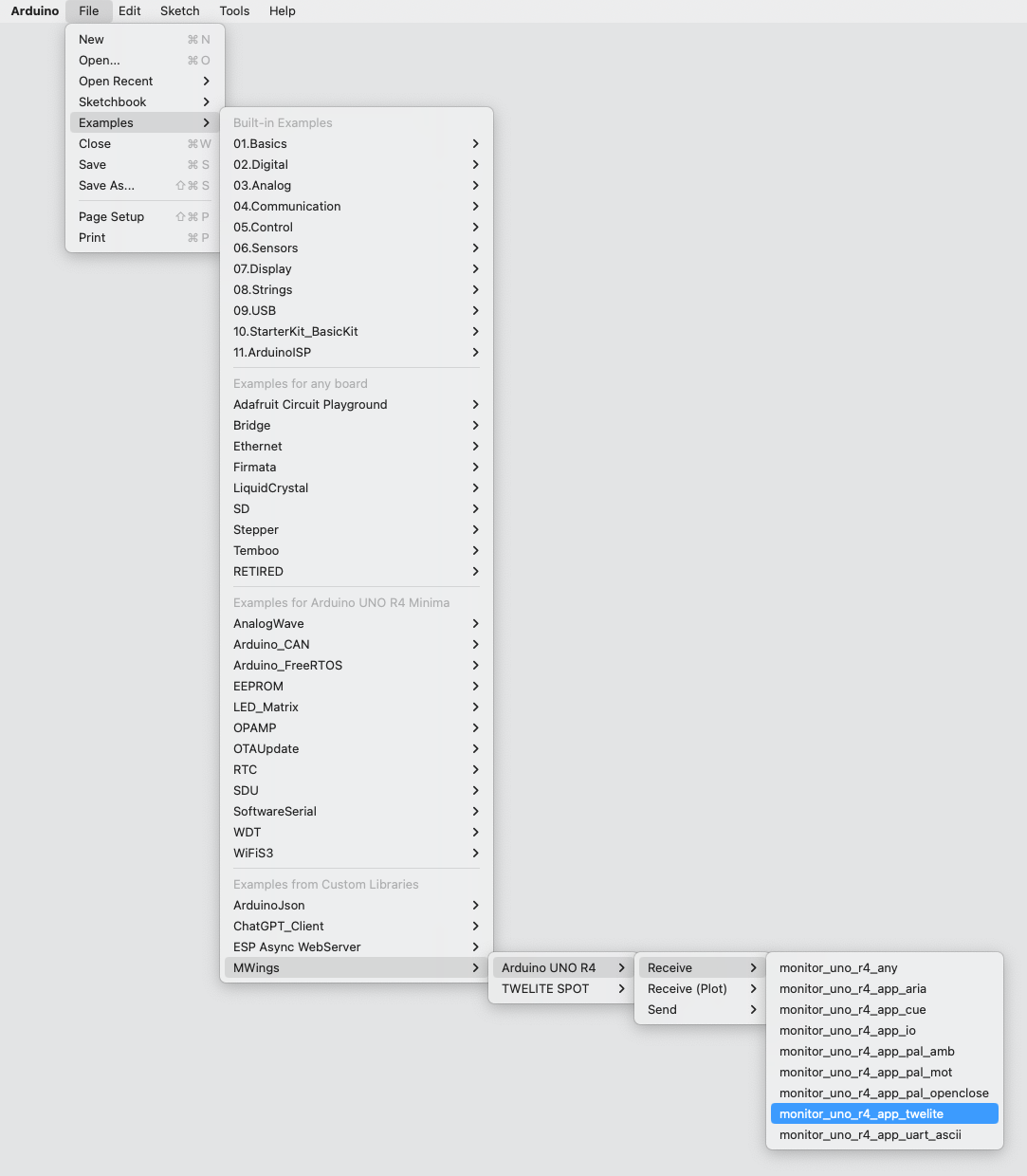
A package for configuring TWELITE, displaying data, and firmware development
1.1 - Installation Method
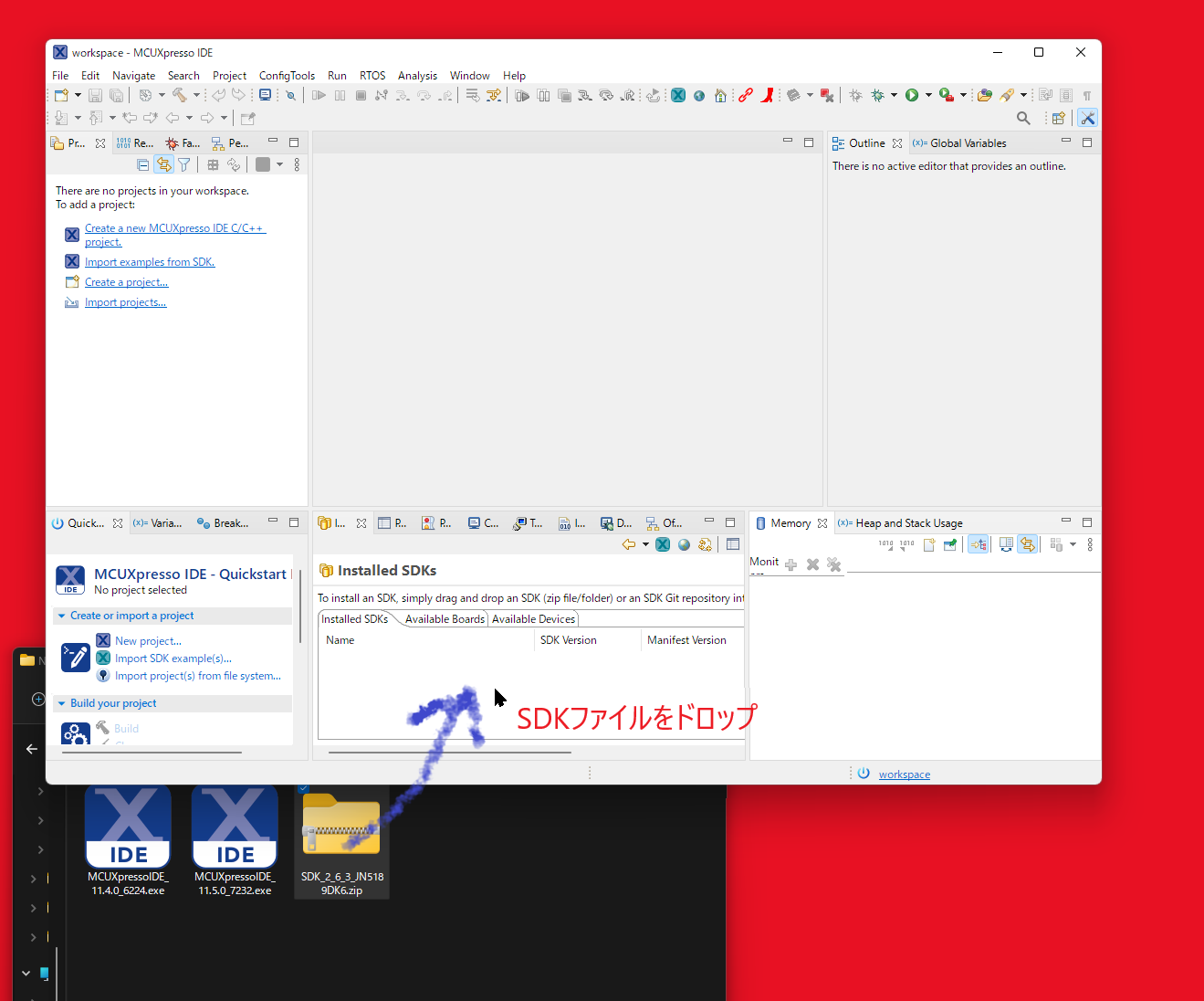
How to install the TWELITE STAGE SDK
Depending on the operating environment, various settings may be required for this application to function properly. If any issues arise, please refer to this document to prepare your environment.
To set up the development environment, it is necessary to install software packages and agree to their licenses. Security settings may also be required.
Although we take great care during distribution, please also verify on your side that the files do not contain viruses or malware.
For security operations (such as whether external applications can be installed), please consult the administrator of your environment.
Please also refer to “Regarding Application Distribution and Execution,” which includes the following:
Verification of the integrity between the original files and downloaded files
Handling of code signing on macOS/Windows
Installation Procedure for TWELITE STAGE SDK
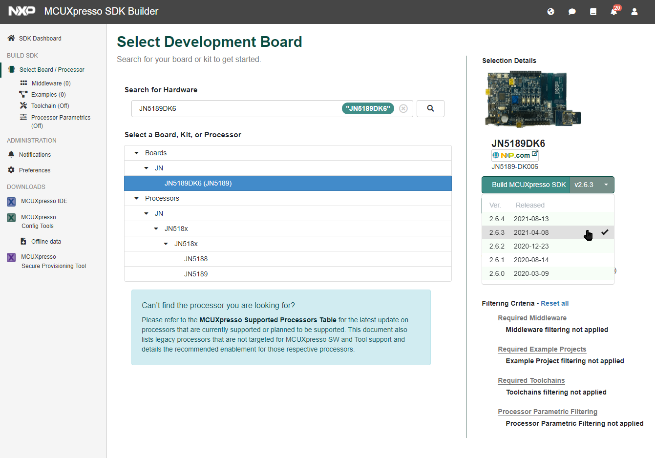
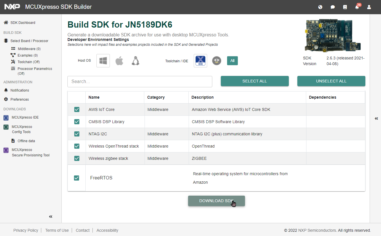
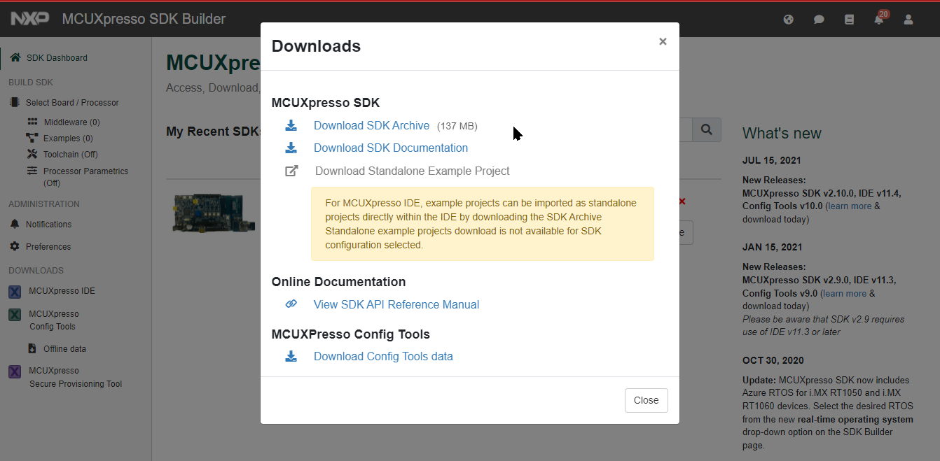
① Obtain the Archive
Download the TWELITE STAGE SDK from the Downloads page.
② Extract the Archive
Extract the downloaded Zip archive.
Do not include spaces, kanji, hiragana, or other characters outside of half-width digits 0..9, half-width alphabets a..zA..Z, and some symbols -_. in the file path of the extraction destination.
Examples for Windows:
NG: C:\work\作業\
NG: C:\Users\user1\work dir\
OK: C:\Work\Work1
③ Check the Files
Check the extracted folder.
The archive extracted on C:\Work is usually expanded to C:\Work\MWSTAGE, but depending on the extraction software, the folder name may differ. Change it if necessary.
In the text, the extracted folder (e.g., C:\Work\MWSTAGE) may be represented as {MWSTAGE Installation}.
The extracted folder {MWSTAGE Installation} contains the following:
TWELITE STAGE APP
For Windows: TWELITE_Stage.exe (standard version), TWELITE_Stage_VSCode.exe (VSCode compatible version)
For macOS: TWELITE_Stage.command (standard version), TWELITE_Stage_VSCode.command (VSCode compatible version)
For Linux: TWELITE_Stage.run (standard version), TWELITE_Stage_VSCode.run (VSCode compatible version)
TWELITE_STAGE - related files of TWELITE STAGE APP
MWSDK - libraries, source code, etc.
Tools - toolchains for building
BIN - .BIN files for TWELITE referenced by the [Select from BIN] menu of TWELITE STAGE APP
log - storage location for logs and database files of TWELITE STAGE APP
flask_wsns_db - simple server using Python, Flask, and sqlite3
TWELITE STAGE APP operates as the frontend application of TWELITE STAGE SDK.
Here, we explain its folder structure.
MWSTAGE/            : TWELITE STAGE SDK installation
  TWELITE_Stage.??? : Executable (Windows .exe, macOS .command, Linux .run)
  TWELITE_Stage.sav : Configuration file
  TWELITE_Stage.ini : Other settings
  TWELITE_Stage/    : Related files of TWELITE STAGE APP

  MWSDK/            : MWSDK libraries etc.
  BIN/              : Storage destination when [Select BIN file] is used
  log/              : Log and database storage destination

  Tools/            : A set of tools including gcc compiler

  flask_wsns_db/    : Simple server using Python, Flask, sqlite3
MWSDK folder
MWSDK/
  Act_samples/        : Sample code using mwx library
  Wks_TweApps/        : Source code of TWELITE APPS
  Act_extras/         : More specialized samples using mwx library, and those referencing other libraries
  TWENET/             : TWENET library (mwx library etc.)
  ChipLib/            : Semiconductor library
  MkFiles/            : Core processing part of Makefile
  docs/               : Library manuals etc.
  LICENSE             : License description of MWSDK
  000manifest         : Version information of MWSDK
  ReleaseNotes.md     : Update history (top page)
  ReleaseNotes_en.md  : Update history (English)
  ReleaseNotes_jp.md  : Update history (Japanese)
The MWSDK folder contains libraries for building TWELITE software, samples, and source code of TWELITE APPS.
TWELITE_Stage.sav
Stores the configuration information of TWELITE STAGE APP.
The file name is the TWELITE STAGE APP executable name + .sav.
MWSDK= Edit this when you want to specify a different folder instead of the MWSDK/ folder. This is useful when mixing multiple library versions. In the above example, the MWSDK2020_10 folder is used.
LANG= Specify LANG=en to set the display language of TWELITE STAGE APP to English.
Running TWELITE STAGE APP with different settings
Copy TWELITE_Stage.exe (for Windows) with a different file name. For example, if changed to TWS1.exe, it refers to configuration files named TRS1.sav and TRS1.ini.
BIN folder
When selecting the [Select from BIN] menu in TWELITE STAGE APP, firmware files (.BIN) in this folder are used.
log folder
When running the serial port logging function in TWELITE STAGE APP, log files are stored in this folder.
This folder is also the storage destination for database files when using the graph function and for outputting csv files.
Tools folder
Contains cross-compiler toolchains such as gcc, g++.
Platform-specific utilities are also stored in this folder. For details, see Tools/readme.txt.
flask_wsns_db folder
Python sample script to access the database created by the sensor graph viewer of TWELITE STAGE APP.
This sample allows viewing tables and graphs in a web browser.
For details, see flask_wsns_db/README.html.
Build project folder
This feature is introduced as a non-standard feature. Behavior may differ from the description.
Folder search order
TWELITE STAGE APP searches build project folders (Act_samples etc.) in the following order:
The folder where TWELITE STAGE APP was started
The folder where the TWELITE STAGE APP executable is located
{MWSDK folder}/..
{MWSDK folder}
MWSDK is searched starting from the folder where the TWELITE STAGE APP executable is located.
Wks_Acts
If you create a Wks_Acts folder, this folder is referenced from the [act Build & Rewrite] menu instead of the Act_samples folder.
Wks_Acts is intended to store projects you create yourself.
1.1.2 - Platform-specific Notes
Platform-specific notes for installation
This document describes notes to consider when installing the TWELITE STAGE APP on each platform.
1.1.2.1 - Notes When Installing on Windows
Notes when installing the TWELITE STAGE APP on Windows
Windows
Environment
The development and operation have been confirmed in the following environment.
Windows 10 Version 1903
Visual Studio 2019 (32bit build)
Handling of Serial Ports
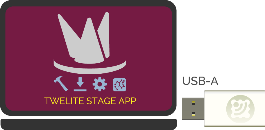
MONOSTICK and TWELITE R series are equipped with FTDI’s USB serial conversion ICs (FT230/FT232 series). To use these, device driver installation may be required.
If the PC does not recognize MONOSTICK or TWELITE R, please install the D2XX driver from https://www.ftdichip.com.
Additional Installation of Visual C++ Runtime Library
In some cases, the Visual C++ redistributable code (runtime library) of Visual Studio 2019 is required.
If an error occurs when starting the application and it does not launch, run TWELITE_Stage¥INSTALL¥VC_redist.x86.exe distributed in this package, or obtain it from Microsoft’s website. Note that the redistributable binary is 32bit.
1.1.2.2 - Notes When Installing on macOS
Notes when installing the TWELITE STAGE APP on macOS
macOS
Environment
The development and operation have been confirmed in the following environments.
macOS 10.14 (Mojave, Intel)
macOS 12 (Monterey, Apple Silicon)
Installing Rosetta 2
Rosetta 2 is required for building applications for the BLUE / RED series.
The build for the BLUE / RED series uses toolchains such as ba-elf-gcc, but Apple Silicon binaries are not available.
Therefore, please use macOS 27 or earlier when building for the BLUE / RED series.
Dependent Software and Warning Dialogs
If the following issues occur, permission to execute or installation is required for the operation of TWELITE_Stage.command.
Although the toolchain is code-signed, if the code signature is not properly verified, you may be prompted to allow execution individually for each executable in the build toolchain (such as ba-elf-gcc).
The downloaded archive is not signed. At runtime, security warnings may appear indicating that the application was downloaded from the Internet.
You may be asked to allow execution from the path where TWELITE_Stage.command is installed.
A dialog for installing the make utility may appear during build execution.
Additional Installation of make Utility
In some cases, you may need to install the make utility.
Depending on the macOS version and other factors, a different procedure may be necessary.
If an error occurs when running make from the command line (zsh), install the Command Line Tools.
xcode-select --install
Once the installation is complete, enter make and check for the following output message.
make
make: *** No targets specified and no makefile found.  Stop.
Handling Serial Ports
MONOSTICK and TWELITE R series are equipped with USB serial converter ICs (FT230/FT232 series) from FTDI (https://www.ftdichip.com). To use these, device driver installation may be required.
If the serial port does not appear even after launching TWELITE_Stage.command, please unload (disable) the FTDI driver.
This utility not only suppresses loading of the OS standard device driver when MONOSTICK or TWELITE R is inserted, but also suppresses loading of device drivers for other devices with the same USB ID.
To unload FTDI-related drivers, execute the following command.
sudo kextunload -b com.apple.driver.AppleUSBFTDI
1.1.2.3 - Notes When Installing on Linux
Notes when installing the TWELITE STAGE APP on Linux
Linux
The USB device ID of TWELITE R2 has changed from the conventional 0403:6001 to 0403:6015. You need to add udev settings.
A 32-bit version is not provided.
Linux environments differ in the types of packages provided depending on the distribution and version. You may need to install packages or configure settings individually.
Please refer to general information using error messages as clues.
Environment
Development and operation have been confirmed on the following environments.
Ubuntu 16.04, 18.04, 20.04
NNLinux Beta8 64bit
CentOS 7
Handling Serial Ports
To recognize MONOSTICK or TWELITE-R from TWELITE STAGE, you need to unload the ftdi_sio module and grant read/write permissions to the USB device.
The USB device IDs are shown below.
Vendor ID 0x0403
Product ID 0x6001 (MONOSTICK, TWELITE R) or 0x6015 (TWELITE R2)
We provide udev setting scripts (for Ubuntu, CentOS) to automate this configuration.
Copy the definitions to /etc/udev/rules.d and reload the settings. After setting, unplug and replug the USB device, then run TWELITE_Stage.run. If the USB device appears on the initial screen, the settings have been applied.
Ubuntu 16.04, 18.04, 20.04
cd ./MWSTAGE/TWELITE_Stage/INSTALL/ubuntu/
sudo ./set_udev_sudo.sh
Definition file (line breaks added for readability)
Register the application according to your desktop environment as needed.
You may not be able to run TWELITE_Stage.run from a file icon on the desktop. This is because the system may not recognize TWELITE_Stage.run as an executable.
Ubuntu 16.04, 18.04, 20.04
We provide a script to generate definition files for Ubuntu.
cd ./MWSTAGE/TWELITE_Stage/INSTALL/ubuntu/
./make_launch_icon.sh
This script creates a .desktop file (application definition) in $HOME/.local/share/applications.
After running the script, the TWELITE STAGE icon will be added to the application list.
1.1.2.4 - Notes When Installing on Raspberry Pi
Notes for installing the TWELITE STAGE APP on Raspberry Pi
RasPi
TWELITE STAGE APP runs on Raspberry Pi except for some models.
Supports mouse and touch screen.
Comes with a build toolchain, allowing compilation.
In addition to the X11 version executable, there is a framebuffer version (nox), as well as a lightweight version that omits translucent effects and others.
Depending on the OS type, version, and installation status of your Raspberry Pi, it may not work or may require recompilation.
Environment
The development and operation have been confirmed in the following environment.
Hardware
Raspberry Pi 3 Model B
LCD Screen: Raspberry Pi Touch Display (7")
Software
Raspberry PI OS (32bit) Lite (Version: August 2020)
Known Issues and Limitations
On the first startup, /dev/serial0 may fail to operate.
Operation of /dev/serial0 on Raspberry Pi 4B has not been verified.
Operation of the touchscreen on Raspberry Pi 4B has not been verified.
Input strings to TWELITE STAGE are also passed as-is to shells or getty running on /dev/tty1. It is recommended to start from /dev/tty1.
It may be affected by other installed or running programs (such as X11).
Extracting the Archive
Extract the downloaded archive file into a folder whose path does not contain spaces or Japanese characters.
Below, it is extracted into the Raspberry Pi home folder.
cd /home/pi
unzip MWSTAGE2020_XX_YYYY.zip
Folder Structure
../MWSTAGE
     TWELITE_Stage.run    TWELITE_Stage app
     BIN/                 Firmware BIN files
     MWSDK/               MWSDK libraries, etc.
     TWELITE_Stage/       TWELITE_Stage app related files
Device Drivers
To recognize MONOSTICK or TWELITE R from TWELITE STAGE, it is necessary to unload the ftdi_sio module and grant read/write permissions to the USB device.
The USB device IDs are as follows:
Vendor ID 0x0403
Product ID 0x6001 (MONOSTICK, TWELITE R) or 0x6015 (TWELITE R2)
A udev configuration script is provided to automate this setting. Copy the definition to /etc/udev/rules.d and reload the settings. After setting, unplug and plug the USB device before running TWELITE_Stage.run. If the USB device is displayed on the screen immediately after startup, the setting has been applied.
cd ./MWSTAGE/TWELITE_Stage/INSTALL/ubuntu/
sudo ./set_udev_sudo.sh
Definition file (formatted with line breaks for readability)
In the above environment, /dev/serial0 can be used by configuring the serial port via raspi-config.
sudo raspi-config
From the menu
  "3 Interface Options    Configure connections to peripherals"
  →"P6 Serial Port Enable/disable shell messages on the serial connection"
Select as follows to disable login shell usage and enable hardware.
  "Would you like a login shell to be accessible over serial?" ->
  "Would you like the serial port hardware to be enabled?" →
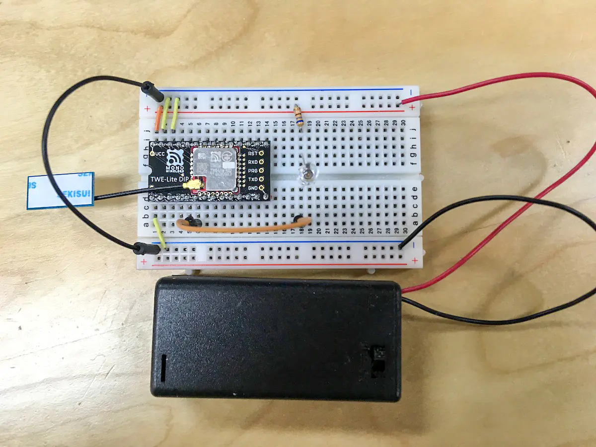
Wiring Example
 [TWELITE]               [Raspberry Pi]
  GND  ------------------ Ground (#6,#9,#14,#20,#25,#30,#34,#39 one of these)
  TXD(DIO6,DIP#10) ------ GPIO15/UART0 RXD (#10)
  PRG(SPIMISO,DIP#7) ---- GPIO23 (#16)
  RXD(DIO7,DIP#3) ------- GPIO14/UART0 TXD (#8)
  RST(RESETN,DIP#21) ---- GPIO22 (#15)
  VCC  ------------------ 3V3 (#1,#17 one of these)
  SET(DIO12,DIP#15) ----- GPIO12 (#32)
Please refer to the manuals of both TWELITE and Raspberry Pi.
DIP# refers to the pin number of the TWELITE DIP.
The above wiring does not guarantee stable operation of TWELITE.
Starting TWELITE STAGE APP
The framebuffer version (nox) does not work on the X11 desktop. Please exit X11.
Run TWELITE_Stage.run. The TWELITE STAGE APP will be displayed on the screen.
Notes
Supports mouse and touch panel.
Input characters in the TWELITE STAGE APP may also be displayed on the console screen.
Others
/dev/dri Error
If the following error appears when starting TWELITE_Stage.run, you can ignore it.
"The path /dev/dri/ cannot be opened or is not available"
Insufficient Memory
If the number of CPUs is 4 or more, parallel compilation will be executed with one less than the number of CPUs during build (3 parallel for 4 cores). Insufficient memory may occur in some cases. In that case, please change the number of parallel jobs.
As of June 2024, Raspberry Pi OS (32bit, bookworm) has a bug where pin control cannot be performed and modules cannot be recognized or operated due to Linux kernel updates.
Also, in bookworm, startup failures due to errors related to libccm and others have been confirmed, but may be resolved by running the following commands.
An application for building, rewriting, configuring, and displaying data.
TWELITE STAGE APP is an application for building and rewriting firmware, configuring TWELITE APPS, and displaying data. It is used with the evaluation and development environment TWELITE STAGE.
1.2.1 - TWELITE STAGE APP Manual
An application for building, rewriting, configuring, and displaying data
TWELITE STAGE APP is an application used for building and rewriting firmware, configuring TWELITE APPS, and displaying data. It is used in the TWELITE STAGE evaluation and development environment.
If you notice any issues, we would appreciate it if you could contact our support desk.
The display examples in this document (button names and screen captures) correspond to the version at the time of document creation. There may be some differences from the version you have obtained.
The Mono Wireless official repository distributes the standalone binary of the TWELITE STAGE app. Please use this if you want to update only the TWELITE STAGE app or obtain the M5Stack version. The version of each binary can be identified from the tags on GitHub.
The TWELITE STAGE app is intended to operate with the latest stable TWELITE STAGE SDK distributed as a stable version. Therefore, the new TWELITE STAGE app may not work correctly with older SDKs.
The source code of the TWELITE STAGE app is placed in examples/TWELITE_Stage.
1.2.1.2 - How to Use
How to use TWELITE STAGE APP
This section explains the screens and operation methods of the TWELITE STAGE APP.
How to Launch the App
To launch the TWELITE STAGE app, execute the executable file located in {MWSTAGE Installation}.
When replacing the executable file of the TWELITE STAGE app due to updates, be sure to copy it to the specified folder {MWSTAGE Installation}. Behavior is undefined if the executable is placed in any other path.
The method of execution varies depending on the platform (Windows, macOS, Linux).
System
Extension
Notes
Windows
.exe
Double-click the executable file in Explorer
macOS
.command
Double-click the executable file in Finder
Linux
RasPi
.run
Depends on the distribution and installation environment.Execute as a command from a terminal window (such as xterm) on the X Window System
Executable Types of the App
The TWELITE STAGE APP has two types of executables.
TWELITE_Stage.{extension} - Launches with standard settings.
TWELITE_Stage_VSCode.{extension} - Configured to “Use VSCode” (settings saved in TWELITE_Stage_VSCode.ini). When the VSCode usage setting is enabled, the app operates in a way suitable for development work using VSCode.
The TWELITE STAGE APP does not produce errors when multiple instances are launched, but some features (such as the sensor graph function) may malfunction if multiple instances are running simultaneously.
Therefore, when running multiple apps at the same time, you need to duplicate the executable and launch separate files. This separates various configuration and input/output files, avoiding mutual interference.
App Interface
When you launch the app, two types of windows are displayed:
Main Window
Displays the user interface of the TWELITE STAGE APP.
The serial port under connection (e.g. TWELITE-R or TWELITE STICK) is displayed in the title bar.
All operations of the TWELITE STAGE APP are performed within this window.
Press the ALT (Cmd) key to display the operating aid screen.
The [ A ][ B ][ C ] buttons appear at the bottom of the screen and are used for operation. These buttons can be pressed and held down to call up sub-functions.
Command Window
Usually not used, but displays auxiliary information.
Shows serial communication content, making it ideal for checking logs.
When launched from the command line, the originating terminal acts as the command window.
Example Screen of TWELITE STAGE APP
Exiting the App
Exit the app by any of the following methods:
Move the mouse pointer to the upper right of the execution screen and press the exit button displayed within the screen.
Close the app window (on macOS, ⌘Q can also be used).
On rare occasions, the execution screen may remain after the exit operation. In such cases, please try the following:
Close the TWELITE STAGE APP command line window.
Force quit the app (refer to your system’s documentation for how to force quit).
1.2.1.2.1 - Key and Mouse Operations
Key and mouse operations for TWELITE STAGE APP
Windows
macOS
Linux
RasPi
This section explains the key and mouse operations used in TWELITE STAGE APP.
Key Operations
Windows
macOS
Linux
RasPi
Key inputs performed while holding down Alt (Cmd) are assigned to operations such as changing the settings of TWELITE STAGE APP. Other key operations generally function as normal text input.
Common Keys
Windows
macOS
Linux
RasPi
Key
Meaning
ESCESC
Quickly press ESC twice. Cancel or return to the previous screen.On some screens, pressing once returns to the previous screen.
ENTER
Enter, Select
BS
Delete one character
Cursor Keys↑↓
Select item
Help Screen
Windows
macOS
Linux
RasPi
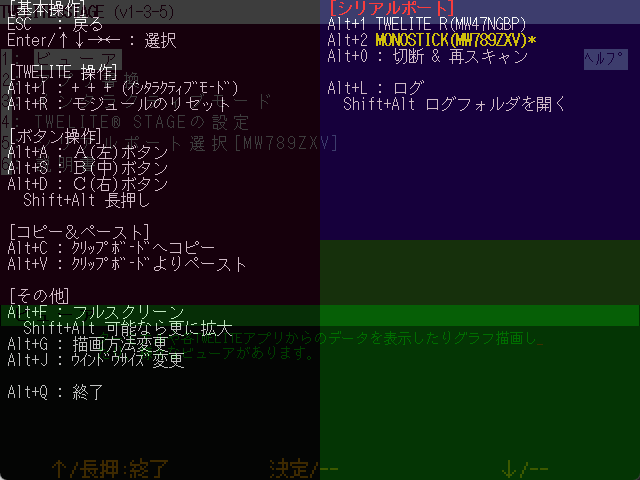
Hold down Alt (Cmd) to display the help screen. The help screen shows explanations of keys that can be used together with Alt (Cmd) and some operational status.
The help screen can also be displayed by moving the mouse pointer to the top-left corner of the screen.
Help Screen
Alt (Cmd) + Operations
Windows
macOS
Linux
RasPi
This section explains operations performed while holding down Alt (Cmd).
In the table below, the Alt (Cmd)+ prefix is omitted. You can check the available keys from the help screen above, but supplementary explanations are provided in the table below.
Alt (Cmd)+ Key
Meaning
I
Inputs + + +. This is the key sequence to enter interactive mode.※ Apps that perform intermittent operation due to sleep are not supported.
R
Resets the module. Controls the reset pin using the functions of TWELITE R or MONOSTICK.
A, S, D
Press buttons A, B, C.
Shift+A, S, D
Long press buttons A, B, C.
C
Copies the text displayed on the screen to the clipboard. (The range varies depending on the screen)
V
Pastes from the clipboard as keyboard input.
F
Switches to full-screen display. If Shift+F is pressed, it enlarges further if possible.
G
Changes the screen rendering method. It emulates a 640x480 LCD screen, but for enlargement, four rendering styles can be selected: (1. LCD monitor style / 2. CRT style / 3. Enlarged with dots emphasized / 4. Enlarged with dots blurred).※ You can change the startup setting in the settings menu.
J
Selects the screen size. Available sizes are {640,480}, {1280,720}, {1280,960}, {1920,1440}, {2560,1440}, {320,240}.※ Can be set as startup setting in the settings menu.
Q
Quits TWELITE STAGE APP.
0
Disconnects the serial port and shows the list of serial ports again.
1, 2, …
Selects the serial port.
B
Change baud rate if serial port is open (9600, 19200, 38400, 57600, 115200, 234000).
L, Shift+L
Starts logging serial port input/output. When finished, the log file opens with Notepad on Windows or Log Viewer on macOS. Shift+L opens the log storage folder.
Other Operations
Key
Meaning
Alt (Cmd)+Shift+Ctrl+m
Opens the MWX library code folder.
Alt (Cmd)+Shift+l
Opens the log folder.
Mouse Operations
Windows
macOS
Linux
RasPi
Mouse operations mainly involve left-clicking, but right-click, right double-click, and the scroll wheel may be used.
Mouse Operation
Meaning
Left click
Select
Left click and drag
Used on some screens (e.g., dragging on graph screens)
Left double-click
Not used
Right click
Used on some screens
Right double-click
Exit the screen (same as ESCESC)
Scroll wheel
Used on some screens (e.g., zoom in/out on graph screens)
Mouse Control of A, B, C Buttons
Windows
macOS
Linux
RasPi
When you move the mouse pointer to the menu display at the bottom of the screen, buttons labeled [ A ], [ B ], and [ C ] appear. TWELITE STAGE APP assigns functions of the hardware buttons arranged in this way to each screen. You can call the functions by left-clicking or long-pressing these buttons. (They can also be selected with Alt (Cmd)+a,s,d or Alt (Cmd)+Shift+a,s,d)
Example of virtual [ B ] button displayed at the bottom of the screen
Mouse Control of Screen Operations
Windows
macOS
Linux
RasPi
On Windows/macOS/Linux, TWELITE STAGE APP screens are basically composed of text only, but menus, buttons, and tabs can be operated with the mouse.
Example of Commander Screen
The screen consists of text only, but the tabs at the top of the screen and inverted text can be selected by left-clicking with the mouse.
1.2.1.2.2 - Screen Operations
Operation instructions for each screen of TWELITE STAGE APP
Windows
macOS
Linux
RasPi
Example of the menu screen
Windows / macOS / Linux / Raspberry Pi
TWELITE STAGE APP is an application launched from the console screen (command line). It outputs information to both the console screen and window screen.
The console screen displays UART output similar to a terminal.
In some environments, the console screen may accept input, but this is not considered an officially confirmed feature.
Raspberry Pi (nox)
Displays on the framebuffer without using X11.
Normally (when started from a shell screen on the framebuffer), the console screen is not displayed.
1.2.1.2.2.1 - Serial Port Selection
Operation instructions for the serial port selection screen
Windows
macOS
Linux
RasPi
Overview
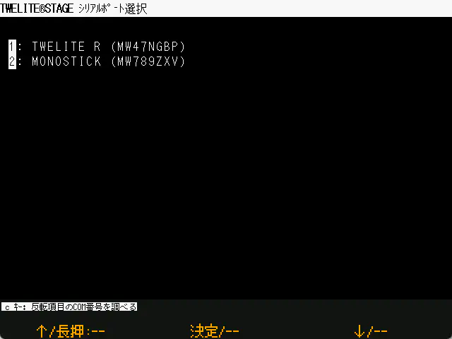
On Windows / macOS / Linux, a screen to select the serial port connected to TWELITE is displayed at startup. However, the serial port can also be connected later.
Example of the serial port selection screen
In the TWELITE STAGE app, the serial port selection and the processing of each screen are not linked. For example, if you start the viewer without selecting a serial port, the display will not update. When you select a serial port in this state, the viewer display will be updated.
Also, the serial port can be switched at any time using the shortcut keys Alt(Cmd) + 0, 1, 2, …
Windows
Press the c key to display the COM port name of the serial port currently highlighted in the list.
Raspberry Pi
On Raspberry Pi, in addition to USB devices, if /dev/serial0 and /dev/serial1 exist, serial0 and serial1 will be displayed. Normally, serial0 is used.
1.2.1.2.2.2 - Main Menu
Operation instructions for the main menu screen
Windows
macOS
Linux
RasPi
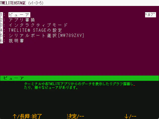
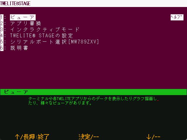
This is the top level of the hierarchical menu.
Example of the main menu screen
On this screen, you select a menu. When a menu is highlighted, a brief explanation is displayed in green text at the bottom.
Viewer: A viewer that interprets and displays packets received from TWELITE. In many cases, the receiving TWELITE is programmed with App_Wings.
Write Firmware: Build the firmware and write it to the connected TWELITE.
Interactive settigns mode: Configure the connected TWELITE settings via interactive mode.
Settings of TWELITE STAGE: Configure various settings of the TWELITE STAGE app.
Select SERIAL port: Select the serial port.
Open MANUAL: Menu to display manuals. Opens the following manuals in a browser:
TWELITE STAGE App (this document)
MWX Library
TWENET_C Library
1.2.1.2.2.2.1 - Viewer
About the viewer
Windows
macOS
Linux
RasPi
The viewer is a feature for displaying information received from a connected TWELITE and sending commands.
Each viewer is a relatively small program that also serves as a sample for how to use the mwm5 library.
1.2.1.2.2.2.1.1 - Terminal
Operation instructions for the Terminal screen
Windows
macOS
Linux
RasPi
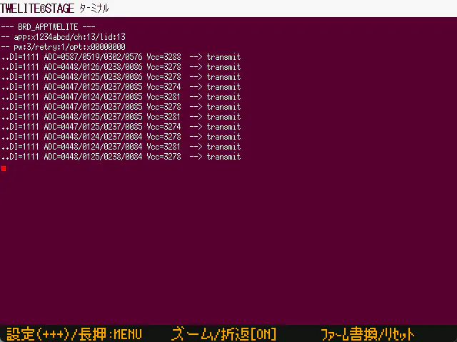
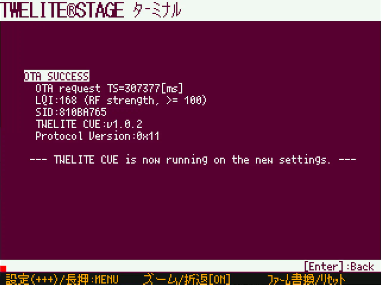
Example of the Terminal screen
Overview
A general VT100-compatible serial terminal.
Supports TWELITE interactive mode and reset control.
Operations
Operation
Description
[ A ]
Input the + + + sequence (interactive mode)
[ A ]Long press
Exit this screen and return to the previous menu.
[ B ]
Display a partial area of the first screen with a larger font.The area is selected so that the cursor is visible on the screen, but depending on the screen output, the desired part may not be visible.
[ B ]Long press
Toggle word wrap ON/OFF.By default, word wrap is enabled, but you can also display without wrapping. Characters beyond the right edge of the screen will not be displayed.
[ C ]
Move to the firmware update screen.During firmware development, source code modification, operation check, build & write are frequently performed, so a shortcut is provided.
[ C ]Long press
Control and reset the TWELITE reset pin.
ESCESC
Press the ESC key twice quickly to exit this screen.※ In most screens, pressing the ESC key once exits the screen, but in the terminal, a single ESC key input is used for other purposes, so double input is assigned.
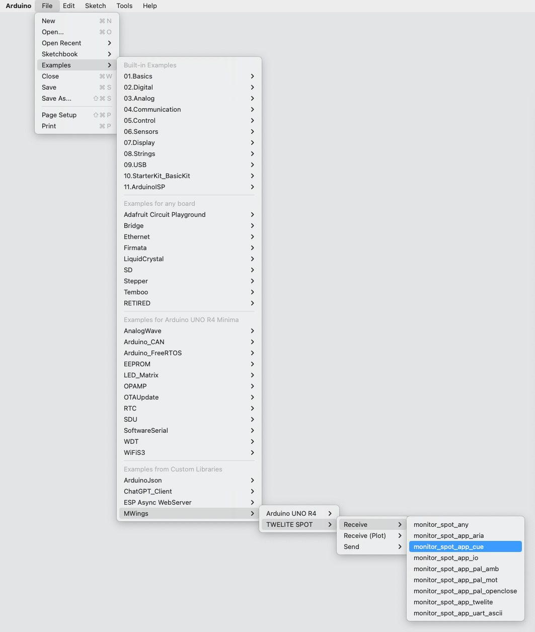
1.2.1.2.2.2.1.2 - Standard App Viewer
Operation instructions for the Standard App Viewer screen
Windows
macOS
Linux
RasPi
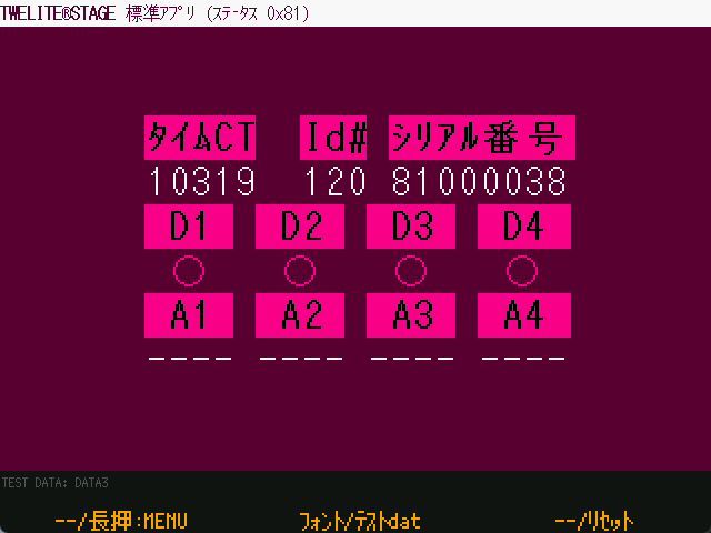
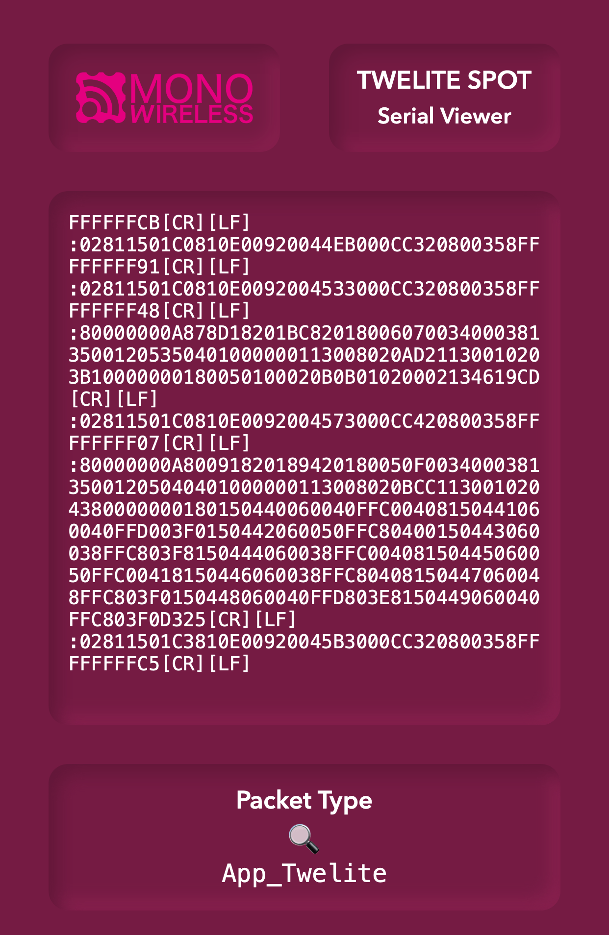
Example of the Standard App Viewer screen
Overview
The TWELITE communicating partner should have App_Twelite (Standard App) programmed. When a message indicating the status of buttons or analog inputs of the Standard App (0x81 message) is received, its contents are interpreted and displayed using the mwm5 parser library.
Please program the TWELITE connected to the PC with either App_Twelite (Standard App) or App_Wings (Parent/Relay App), and confirm that the data received from the communicating TWELITE is displayed in the terminal before use.
Operations
Operation
Description
[ A ]
No assignment
[ A ]Long press
Exit this screen and return to the previous menu.
[ B ]
Change the font.
[ B ]Long press
Display the screen with test dummy data.
[ C ]
No assignment
[ C ]Long press
Control the reset pin of the TWELITE to reset it.
ESCESC
Press the ESC key twice to exit this screen.
1.2.1.2.2.2.1.3 - Graph
List of graph screens
Accelerometer Real-Time Graph: Displays accelerometer sensor packets in real time. Frequency domain display and CSV file saving are available.
Sensor Graph: Saves data from various TWELITE sensors into an sqlite3 database and displays graphs.
1.2.1.2.2.2.1.3.1 - Accelerometer Real-Time Graph
Operation instructions for the Accelerometer Real-Time Graph screen
Windows
macOS
Linux
RasPi
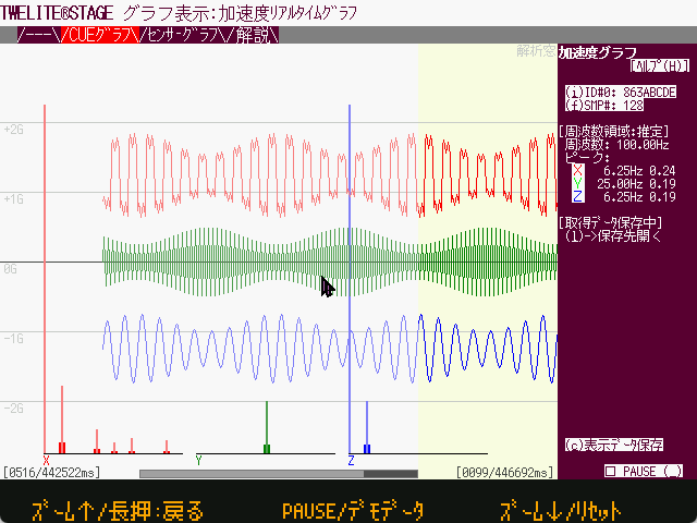
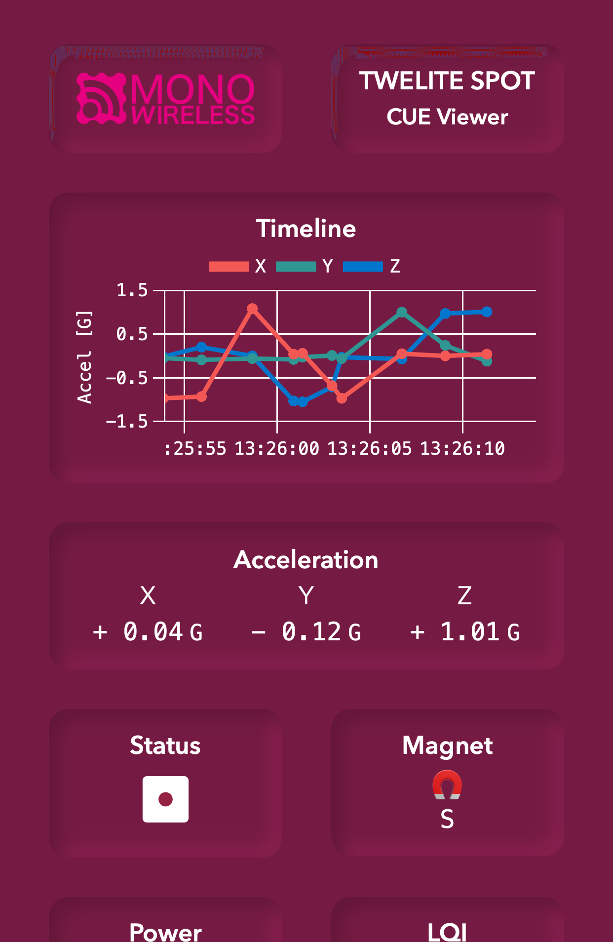
Example Display of Demo Data
Overview
This refers to packets received from TWELITE CUE and TWELITE Motion Sensor PAL. It can display accelerometer data in real-time, and includes features for frequency analysis and CSV export.
In the Accelerometer Real-Time Graph, each sample data is processed separately.
On the other hand, the Sensor Graph records one packet as one sample, even when continuous measurement with multiple samples per packet is performed.
It supports three modes: CUE mode, MOT mode, and 2525 FIFO mode.
When a continuous series of samples reaches a certain number (analysis window), frequency analysis of the XYZ axes is displayed. However, in 2525 FIFO mode, it is assumed to be always continuous.
When packet boundaries are explicit (e.g., when more than 3 seconds have elapsed since the previous packet, in CUE mode for each packet, or in MOT mode when the packet sequence number is discontinuous), four dummy samples are inserted and a pink background is shown.
Data from up to four nodes are stored on a first-come, first-served basis.
When operating multiple nodes, packet collisions cause many communication failures. Especially in FIFO mode, transmission intervals are almost fixed, and nodes try to transmit packets nearly simultaneously, which may cause prolonged transmission failures due to interference. As a rule, operate one node per wireless channel.
Typical settings for Motion Sensor PAL mode when using the Accelerometer Real-Time Graph are as follows:
To measure continuously at about 25Hz
t: set Transmission Interval (0)
p: set Sensor Parameter (03000000)
To measure continuously at about 50Hz
t: set Transmission Interval (0)
p: set Sensor Parameter (03000100)
To measure continuously at about 100Hz
t: set Transmission Interval (0)
p: set Sensor Parameter (03000200)
To measure 128 samples at about 100Hz every ~10 seconds
t: set Transmission Interval (10)
p: set Sensor Parameter (03000208)
To measure 256 samples at about 100Hz every ~10 seconds
t: set Transmission Interval (10)
p: set Sensor Parameter (03000210)
To measure 64 samples at about 50Hz every ~10 seconds
t: set Transmission Interval (10)
p: set Sensor Parameter (03000104)
To measure 128 samples at about 200Hz every ~10 seconds
t: set Transmission Interval (10)
p: set Sensor Parameter (03000308)
Operation
Operation
Description
Top right(i)ID# button
Click to switch the ID.(Note: Continuous sample data in FIFO mode is not suitable for multi-ID operation)
Top right(f)SMP# button
Click to change the analysis window size among 64, 128, and 256.
Bottom right(c)Save Display Data button
Exports data in CSV format to the log folder.Outputs from the oldest sample in the buffer to the latest sample at the right edge of the screen.(Note: The output is always 5120 samples, with the latest data at the end)
Bottom rightPAUSE( ) button
Pauses display updates.(Note: Samples are still collected until the internal temporary sample buffer is full)
Mouse drag(Graph area)
Moves the position of displayed samples.
Mouse drag(Bottom scrollbar)
Moves the displayed sample position in larger steps.
Arrow keys→←
Moves the sample display area.
Arrow keys↑↓
Zooms in/out on the horizontal axis of samples (1x / 2x / 3x / 4x).(Note: Up to 2x when the analysis sample count is 256)
Sample Rate Estimation
The sampling rate is calculated from the packet reception times. It averages the reception times of multiple past samples to estimate one sample interval, so packet drops may cause significant errors.
Also, the related log timestamp (T_SMPL) is an estimated value and is delayed compared to the packet acquisition time.
Once sample rate estimation completes, graph scrolling becomes smooth.
Opening the CUE Graph Mode on Startup
Specify 31 in [STAGE Common Settings → Startup App Selection].
Log Output (Save Display Data)
Pressing the (c) Save Display Data button outputs up to 512 samples starting from the current display position (rightmost sample).
Note that the latest samples are recorded at the end, so there may be no data at the beginning.
Log file name is {log folder}/acc_snap_{timestamp}.csv.
Data has the newest sample at the right edge as sample number 512 (file end).
When frequency analysis is performed, the last samples used for frequency analysis are included.
Frequency analysis results are added to rows containing frequency analysis target samples (for 64 samples, results appear from sample 449 for 32 rows, showing from DC to high frequency components).
Label
Item Name
Description
#
SampleNumber
T_PKT[ms]
PacketReception Time
Multiple samples may be included in one packet, so samples with the same timestamp are listed.
SEQ
PacketSequence Number
Assigned to each packet; continuity indicates no packet loss.
T_SMPL[ms]
SampleTime (Virtual/Estimated)
Timestamp generated for each sample from packet reception time.Does not match the actual sampling time.(Note: Sample rate is estimated from packet reception intervals, and sample times are cumulatively added, so timestamps are delayed by one packet interval compared to actual sample time)
X[G]
X-axis Sample Value
Unit is G. Based on sensor values.
Y[G]
Y-axis Sample Value
Unit is G. Based on sensor values.
Z[G]
Z-axis Sample Value
Unit is G. Based on sensor values.
FD#
Frequency Analysis Calculation Index
For 64 samples, ordered as DC,1,2,...,31.
Hz
Frequency Analysis Frequency Axis Value
Estimated frequency, calculated as (FD# / FD_Len) * FD_Freq.
System time when the log file was opened(Note: TWELITE STAGE app side)
Date
Date when the log file was opened
Time
Time when the log file was opened
Time_Msec_part
Sub-second part of time when the log file was opened [ms]
Samples
Valid sample data
FD_Len
Frequency analysis sample count
FD_Start#
Frequency analysis start sample number
FD_Freq
Estimated frequency range for frequency analysis [Hz](Note: estimated from sample reception interval)
Log Output (Auto Save)
When the Accelerometer Real-Time Graph screen is opened and data is input, log files are automatically saved.
Log file name is log folder/accel_{serial number}_{timestamp}.csv.
While the screen is open, files are being written, so they may not be available for reading or may be incomplete.
Label
Item Name
Description
#
SampleNumber
T_PKT[ms]
PacketReception Time
Multiple samples may be included in one packet, so samples with the same timestamp are listed.
SEQ
PacketSequence Number
Assigned to each packet; continuity indicates no packet loss.
T_SMPL[ms]
SampleTime (Virtual/Estimated)
Timestamp generated for each sample from packet reception time.Does not match the actual sampling time.(Note: Sample rate is estimated from packet reception intervals, and sample times are cumulatively added, so timestamps are delayed by one packet interval compared to actual sample time)
System time when the log file was opened(Note: TWELITE STAGE app side)
Date
Date when the log file was opened
Time
Time when the log file was opened
Time_Msec_part
Sub-second part of time when the log file was opened [ms]
1.2.1.2.2.2.1.3.2 - Sensor Graph
Operation instructions for the Sensor Graph screen
Windows
macOS
Linux
RasPi
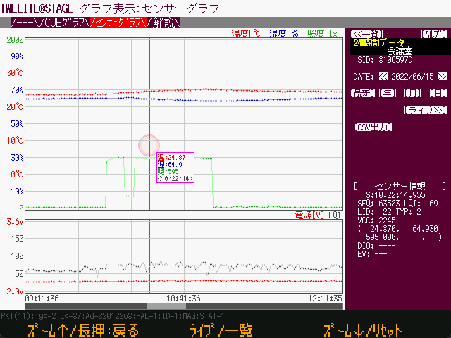
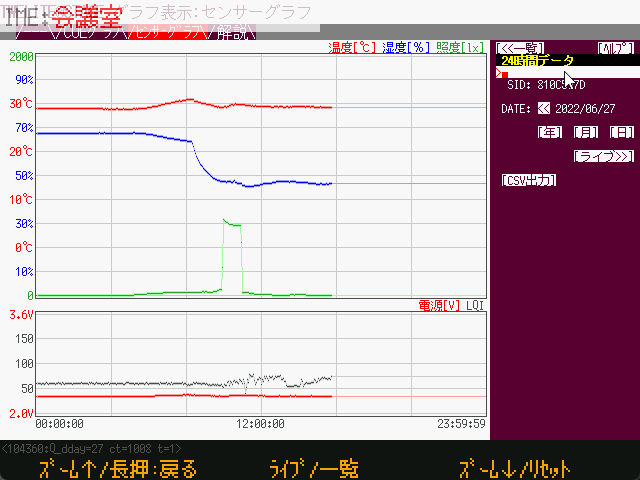
Example of data display
Overview
Various sensor data are recorded in an SQLite database and displayed on the screen in graph format. The database file can also be accessed by external applications.
You cannot run multiple instances of TWELITE STAGE APP with the same executable name to use the Sensor Graph simultaneously.
The database file is stored in the {MWSTAGE Installation}/log folder, and the filename is determined based on the executable name of TWELITE STAGE APP. If the executable names are the same, they will refer to the same database file. The TWELITE STAGE APP implementation does not assume multiple apps add data to the same database simultaneously. In some cases, this may cause database file access errors and cause TWELITE STAGE APP to crash.
For example, if you want to connect two MONOSTICK devices to a PC and run multiple “Sensor Graph” instances simultaneously, run multiple TWELITE STAGE apps with different executable names (e.g., TWELITE_Stage_a.exe, TWELITE_Stage_b.exe). The database filenames will be log/TWELITE_Stage_a_WSns.sqlite and log/TWELITE_Stage_b_WSns.sqlite, respectively.
The database uses SQLite (sqlite3) and is stored in the file {MW_STAGE Install}/log/{executable_name}_WSns.sqlite.
Specify 32 in [STAGE Common Settings → Launch App Specification].
About the Database Tables
sensor_data
Stores received data.
Column Name
Type
Description
_uqid
INTEGER
Sequential number used in the database
sid
INTEGERint32_t
Serial number stored as int32_t type.For example, a serial number “8123abcd” is stored as the integer value -2,128,368,691.
ts
INTEGERint64_t
Timestamp when the system received the packet, stored as int64_t.UNIX epoch (seconds since 1970).
ts_msec
INTEGER
Milliseconds part of the timestamp.
year
INTEGER
Year part of the local time from the timestamp.
month
INTEGER
Month part of the local time from the timestamp.
day
INTEGER
Day part of the local time from the timestamp.
hour
INTEGER
Hour part of the local time from the timestamp.
lid
INTEGER
Identifier such as LID assigned by the user.
lqi
INTEGER
Link Quality Indicator, an estimate of reception strength.
pkt_seq
INTEGER
Packet sequence number. The range of values depends on the firmware.
pkt_type
INTEGER
Type of wireless packet.2 PAL AMB6 ARIA1 PAL MAG*3 PAL MOT5 CUE0x101 App_Twelite*0x103 App_IO*Currently unsupported types
value
REAL
Measured value (definition varies by packet type).pkt_type->2,6: Temperature [°C]1: Magnet detection (00->No magnet, 01->N pole, 02->S pole)3,5: X-axis acceleration (average if multiple samples in packet) [G]0x101,103: Input IO bitmap (same as lower 8 bits of val_dio)
value1
REAL
Measured value (definition varies by packet type).pkt_type->2,6: Humidity [%]1: Unused3,5: Y-axis acceleration (average if multiple samples in packet) [G]0x101: ADC1 [V]103: Unused
value2
REAL
Measured value (definition varies by packet type).pkt_type->2: Illuminance [lx]6: Unused1: Unused3,5: Z-axis acceleration (average if multiple samples in packet) [G]0x101: ADC2 [V]103: Unused
value3
REAL
Measured value (definition varies by packet type).pkt_type->2: Unused6: Unused1: Unused3,5: Unused0x101: ADC3 [V]103: Unused
val_vcc_mv
INTEGER
Power supply voltage [mV]
val_dio
INTEGERint32_t
b0..b7: Values of DI1..DI8 (1 is LOW, 0 is HIGH level)b24..b25: Magnet value (if b28 is 1): 00->No magnet, 01->N pole, 10->S poleb28: If 1, magnet data is stored in b24..b25b31: Periodic transmission bit (magnet only)
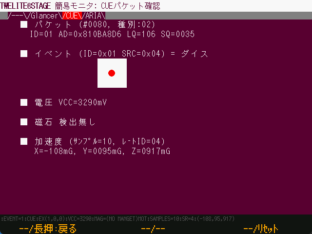
In CUE mode, acceleration events are always output.
Regardless of the wake-up factor, a fixed number of acceleration samples are measured after waking. Events are determined based on the acceleration measurement results.
Event
Number
Description
Dice
1(0x00) .. 6(0x06)
Determined based on periodic wake-up and magnetic sensor wake-up.If a large acceleration is detected after waking,an undetermined event (0xFF) may be detected.
Move
16(0x10)
Occurs when the acceleration sensor detects acceleration above a threshold,resulting in a move or shake event.Move occurs when the measured acceleration change is relatively small,(acceleration change detected but no continuous acceleration change).
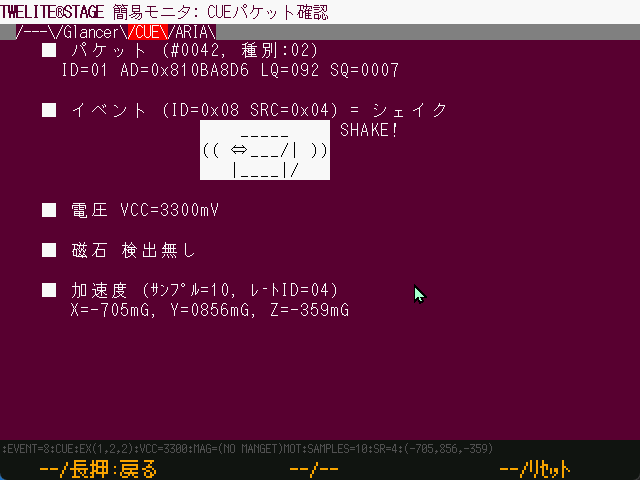
Shake
0x08
Occurs when the acceleration sensor detects acceleration above a threshold,resulting in a move or shake event.Shake occurs when the measured acceleration change is relatively large,(continuous acceleration changes detected).
Quantitative definitions for acceleration thresholds and event detection conditions are not provided.
Voltage
Power supply voltage of the module [mV].
Magnet
Displays the detected magnetic pole or no detection.
There is no function to indicate whether wake-up was caused by magnetic sensor detection.
Acceleration
Displays acceleration measured after waking.
Samples: Displays the number of acceleration samples, fixed at 10 samples.
Rate ID: Sample rate of acceleration, fixed at 04 (100Hz).
X, Y, Z: Acceleration on three axes. Calculated as the average of 8 samples. Unit is milli-G (1000mG = 1G = 9.8m/s²).
Example Screens
Example of Move Event Detection
Example of Shake Event Detection
1.2.1.2.2.2.1.4.2 - ARIA Viewer
Operation instructions for the ARIA Viewer screen
Windows
macOS
Linux
RasPi
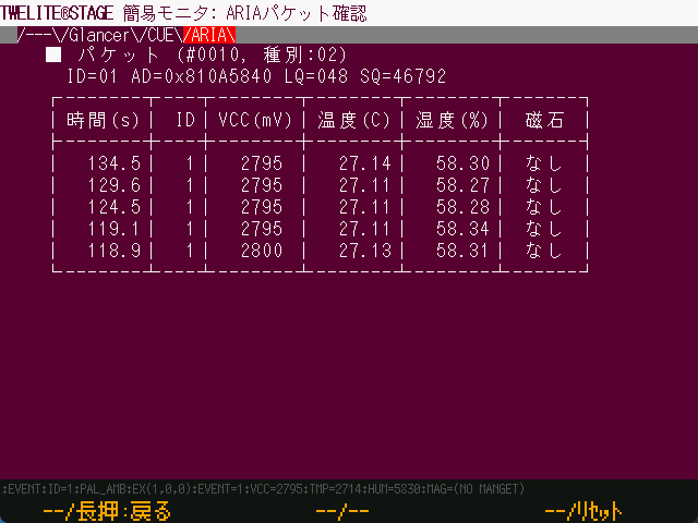
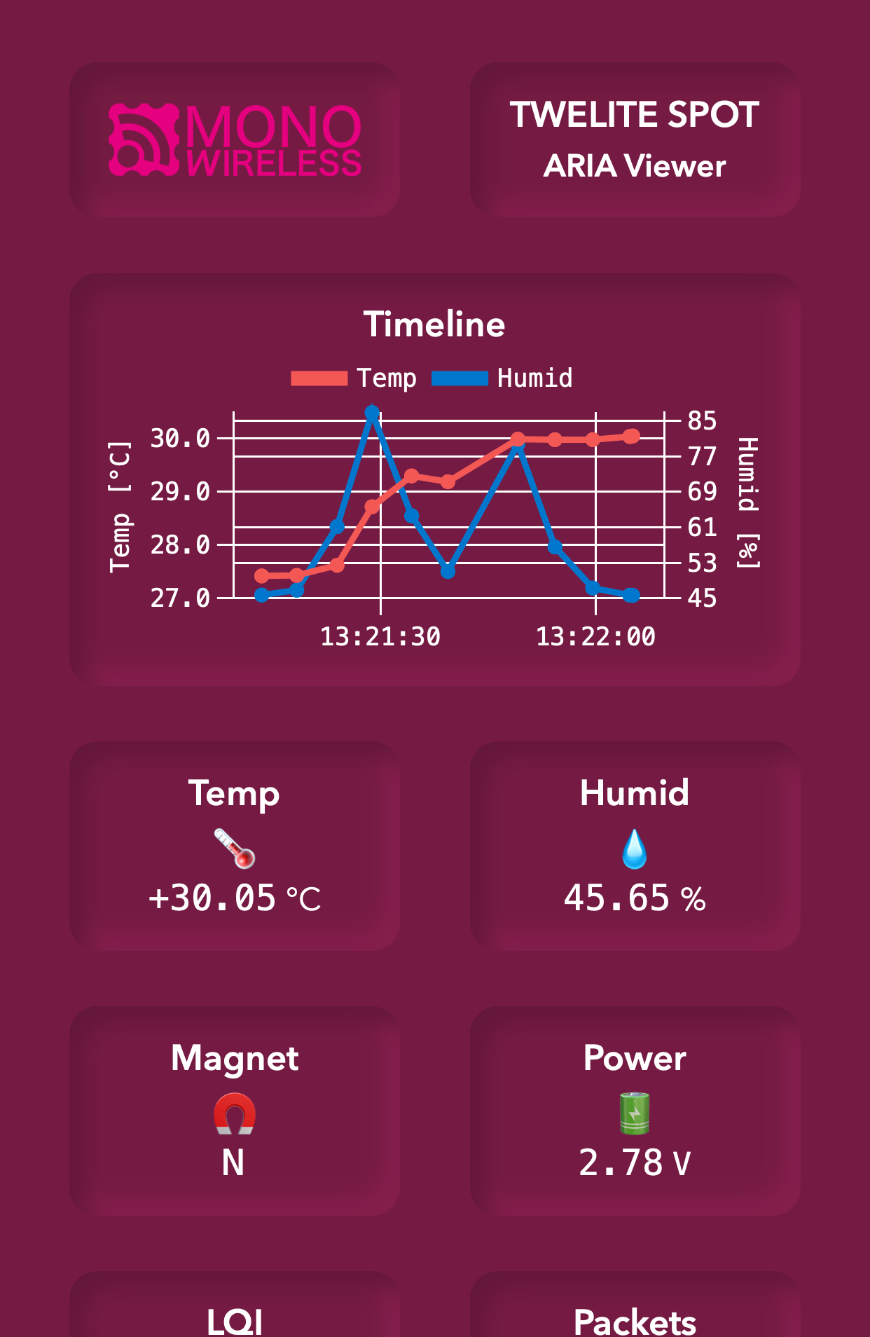
This page contains capture images from an older version.
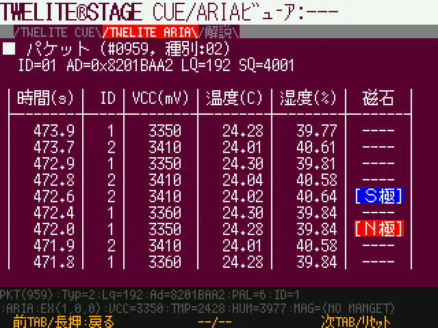
Example display of temperature and humidity data table
Overview
Interprets and displays messages received from TWELITE ARIA.
By programming the connected TWELITE with App_Wings, it can display information received from communication partners’ TWELITE devices (App_Twelite, TWELITE PAL, … as long as the application ID and frequency channel match, mixed operation is possible).
Glancer is an English word meaning a person who glances (i.e., takes a quick look).
Operation
Use by switching between the list display screen and the selection display screen.
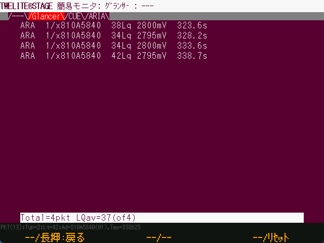
List Display
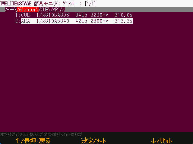
Example of list display
Lists information from communication partners.
Displayed content includes message type, logical device ID, serial ID, LQI (Lq), power voltage (if included in the information), and timestamp.
Operation
Description
[ A ]
Move to the previous item in the list.
[ A ]Long press
Exit this screen and return to the previous menu.
[ B ]
Switch to selection display.
[ B ]Long press
Sort items.The sort key changes sequentially each time sorting is performed.
[ C ]
Move to the next item in the list.
[ C ]Long press
Control the TWELITE reset pin and reset it.
ESC
Exit this screen.
Selection Display
Example of selection display
By moving items and highlighting one in the list display, then performing a selection operation, you transition to this screen. It shows information related to a specific communication partner in order of arrival.
The number of received packets and the average LQI since selection are displayed.
Operation
Description
[ A ]
No assignment
[ A ]Long press
Exit this screen and return to the previous menu.
[ B ]
No assignment
[ B ]Long press
No assignment
[ C ]
No assignment
[ C ]Long press
Control the TWELITE reset pin and reset it.
ESC
Return to the list display screen.
1.2.1.2.2.2.1.5 - Commander
Operation instructions for the Commander screen
Windows
macOS
Linux
RasPi
Overview
Commander is a feature to send serial messages to TWELITE.
Operation
The first screen of the Commander displays important notes.
At the top of the screen, there are tabs represented by text, which you can navigate by clicking with the mouse to switch between tab screens.
Operation
Description
[ A ]
Move tab (left)
[ A ]Long press
Exit this screen and return to the selection screen.
[ B ]
No assignment
[ B ]Long press
No assignment
[ C ]
Move tab (right)
[ C ]Long press
Control the reset pin of TWELITE to reset it.
ESC
Exit this screen and return to the selection screen.
Make sure the connected TWELITE has App_Twelite or parent/relay app (App_Wings) programmed, and after setting the application ID and channel, confirm that messages are being received from the communication partner.
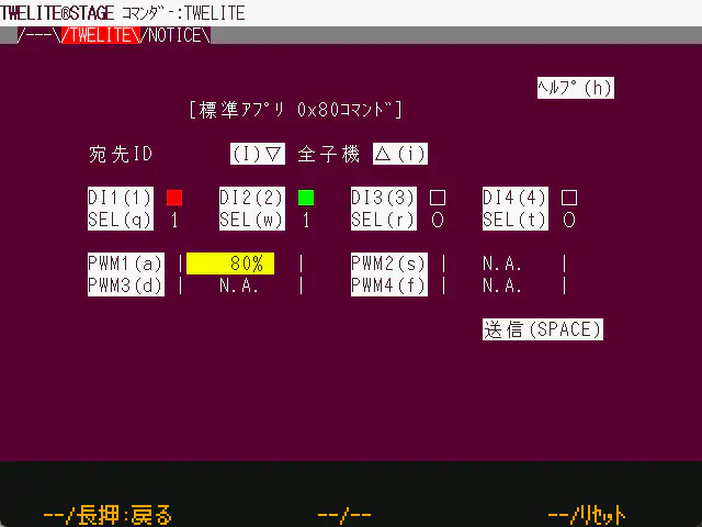
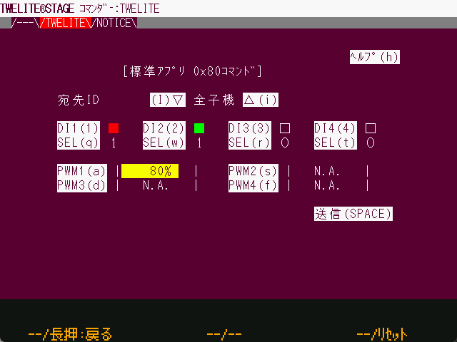
Example display of the TWELITE tab
Item
Description
Destination
Specify the TWELITE to send to.If you are a child device, specify “Parent:0”.If you are a parent device, specify “All children = 0x78” or a specific child ID (can be specified from 1 to 8).
DI1..DI4
Settings state from DI1 to DI4.■ means selected (LOW = GND level), □ means (HIGH = VCC level).Please specify SEL in the next item.
SEL
Selection bits for each DI.(If 0, the DI specification is ignored; if 1, the specification is enabled.)
PWM1..4
Set the PWM duty ratio.0 corresponds to GND level, 1024 (100%) corresponds to VCC level.PWM ports set to N.A. will not be changed.(Note: On the MW-STA-KIT-0/MW-STA-SOLO-0 boards, PWM1 is pulled up to VCC, so the LED lights brightest at 0 and turns off at 100%.)
Commands are generated each time an item is changed. Pressing the send button will resend the command with the current settings.
Make sure the connected TWELITE has App_Wings programmed, and after setting the application ID and channel, confirm that messages are being received from the communication partner.
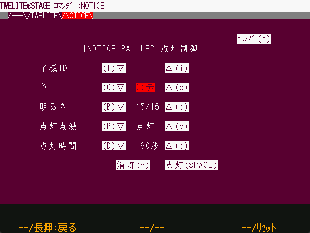
Example display of the NOTICE tab
Item
Description
Destination
Specify the ID of the TWELITE PAL to send to.Valid range is 1 to 8.
Color
Specify the lighting color from 7 colors.There are two types of white: one is RGB mixed color, and the other is a single white LED lit.
Brightness
Specify from 0 to 15. 0 means off.
Lighting/Blinking
Select lighting or blinking pattern.
Lighting Time
Automatically turns off after a certain time has passed since the command was issued.
Turn off (x)
Generate a turn-off message to turn off the LED.
Turn on (SPACE)
Send the current settings to turn on the LED.
Commands are generated each time an item is changed. Pressing the send button will resend the command with the current settings.
Display at the bottom of the screen
At the bottom of the screen, the timestamp when the command was generated and the command starting with : are displayed. The clipboard copies the contents of this screen.
1.2.1.2.2.2.2 - Write App Firmware
About the firmware writing function
Windows
macOS
Linux
RasPi
The firmware writing function allows you to write the TWELITE app (firmware).
Write pre-built .BIN files
Build from source files such as act and write
It eliminates the hassle of building source files, terminal disconnection, launching the writing utility, and terminal connection.
Automatically recognize TWELITE
After writing is complete, reset and then transition to interactive mode or terminal
From the list of projects, launch the project folder or environments like VSCode (except Raspberry Pi version)
From the list of projects, open related information web pages (except Linux and Raspberry Pi versions)
1.2.1.2.2.2.2.1 - Select from BIN
Operation instructions for the Select from BIN screen
Windows
macOS
Linux
RasPi
Overview
You can write pre-built applications ( .BIN files ).
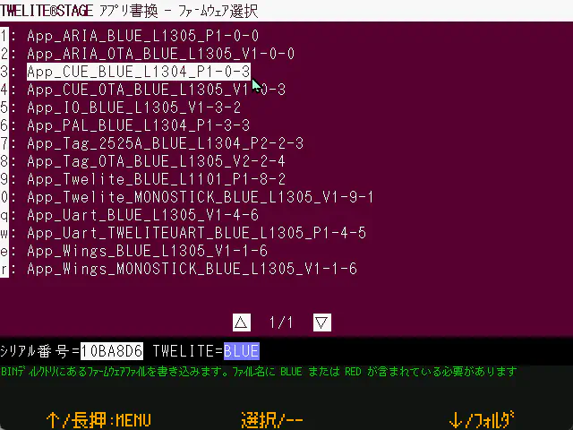
Example of the Select from BIN screen
When you select the menu, a list of .BIN files will be displayed. Please select the firmware to write.
If you want to use a file other than the pre-prepared .BIN files, please store the file to be written in the following location before selecting the menu.
Platform
Location
Windows, macOS, Linux, Raspberry Pi
{MWSTAGE folder}/BIN
In the BIN folder, please store .BIN files built with TWELITE STAGE without renaming the files (they are stored under the build folder of each project).
This function identifies TWELITE (BLUE/RED, etc.) from the file name.
1.2.1.2.2.2.2.2 - act Build & Write
Operation instructions for the act build & write screen
Windows
macOS
Linux
RasPi
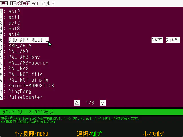
Overview
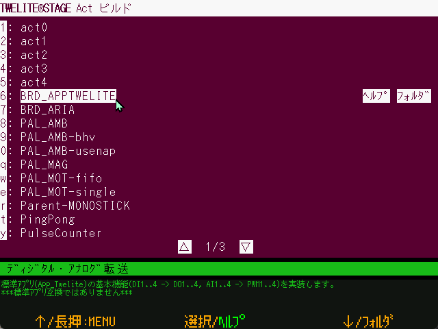
You can build and rewrite acts (act) written with the MWX library.
Example of sample act selection screen
This screen displays a list of projects using acts placed in the following path.
{MWSTAGE installation folder}/MWSTAGE/Act_samples
By default, it includes relatively small projects intended for use as samples.
Operation
You can build and write by selecting the project to write from the list.
After writing is finished, pressing ENTER or the [ B ] button will reset the TWELITE and transition to the interactive mode screen (or terminal screen, depending on settings).
If you have enabled the setting to use VSCode (Open folder in code under app rewrite), it will not build but open the screen to write the .BIN file under build/.
Operation
Description
[ A ]
Menu selection up
[ A ]Long press
Exit this screen and return to the selection screen.
[ B ]
Select
[ B ]Long press
Open related website in the OS default browser.(If registered in 000desc.txt in the project folder)
[ C ]
Menu selection down
[ C ]Long press
Open folder (project or related folder).You can set it to open with VS Code in the settings menu.
ESC
Exit this screen and return to the app rewrite menu.
Mouse click [Help]
Open related website.
Mouse click [Folder] or [VSCode]
Open related folder.
Mouse click [▽] or [△]
Move to next page or previous page.
1.2.1.2.2.2.2.3 - TWELITE APPS Build & Write
Instructions for operating the TWELITE APPS Build & Write screen
Windows
macOS
Linux
RasPi
Overview
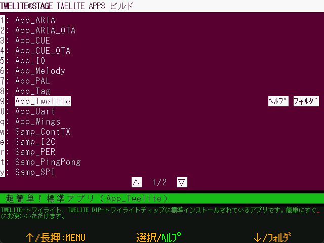
You can build and write TWELITE APPS written with the TWENET C library.
Example of the app selection screen
This screen displays a list of projects located in the following path:
{MWSTAGE installation folder}/MWSTAGE/Wks_TweApps
By default, it includes relatively large-scale projects intended for immediate use.
Operation
By selecting the project to write from the list, you can perform build and write operations.
After writing is completed, pressing ENTER or the [ B ] button will reset the TWELITE and transition to the interactive mode screen (or terminal screen, depending on settings).
If you have enabled the setting to use VSCode (Open folder with code in App Write), the build will not be performed, and the screen to write .BIN files under build/ will open instead. Screen
Operation
Description
[ A ]
Menu selection up
[ A ]Long press
Exit this screen and return to the selection screen.
[ B ]
Select
[ B ]Long press
Open the related website in the OS default browser.(If registered in the project folder’s 000desc.txt)
[ C ]
Menu selection down
[ C ]Long press
Open folders (project, related folders).You can set to open with VS Code in the settings menu.
ESC
Exit this screen and return to the App Write menu.
Mouse click [Help]
Open the related website.
Mouse click [Folder] or [VSCode]
Open the related folder.
Mouse click [▽] or [△]
Move to the next or previous page.
1.2.1.2.2.2.2.4 - Act_extras
Operation instructions for the Act_extras screen
Windows
macOS
Linux
RasPi
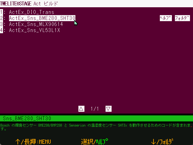
Overview
You can build and rewrite acts written with the MWX library.
Example of the act selection screen
This screen displays a list of projects using acts placed in the following path:
{MWSTAGE installation folder}/MWSTAGE/Act_extras
Unlike act build & rewrite, this includes projects that perform relatively complex processes intended for sample use, or projects that use external open source libraries.
Operation
By selecting a project to write from the list, you can perform build and write operations.
After writing is complete, pressing ENTER or the [ B ] button will reset the TWELITE and transition to the interactive mode screen (or terminal screen, depending on settings).
If you enable the setting to use VSCode (Open folder in code under App rewrite), the build will not be performed, and the screen to write .BIN files under build/ will open instead: screen.
Operation
Description
[ A ]
Menu selection up
[ A ]Long press
Exit this screen and return to the selection screen.
[ B ]
Select
[ B ]Long press
Open the related website in the OS default browser.(If registered in the project folder’s 000desc.txt)
[ C ]
Menu selection down
[ C ]Long press
Open the folder (project or related folder).You can set it to open with VS Code in the settings menu.
ESC
Exit this screen and return to the app rewrite menu.
Mouse click [Help]
Open the related website.
Mouse click [Folder] or [VSCode]
Open the related folder.
Mouse click [▽] or [△]
Move to the next or previous page.
1.2.1.2.2.2.2.5 - Folder (Specify)
Write a specified firmware
Windows
macOS
Linux
By dragging and dropping a folder or .BIN file onto the TWELITE STAGE APP screen, you can write a specific project. Select the dropped target when performing build or write operations.
When you drop a .BIN file, the firmware list in the folder containing that file will be displayed, just as if you had dropped the folder itself.
1.2.1.2.2.2.2.6 - Last (Re-execute)
Re-execute writing the most recently written firmware
Windows
macOS
Linux
RasPi
Re-select the most recently rewritten or specified project.
Depending on the item, one of the following will be performed:
Rewrite the selected project
Redisplay the list of recently selected projects
1.2.1.2.2.2.2.7 - Build & Write Screen
Operation instructions for the build & write screen
Windows
macOS
Linux
RasPi
This section provides operation instructions for the screen displayed when building or writing a project.
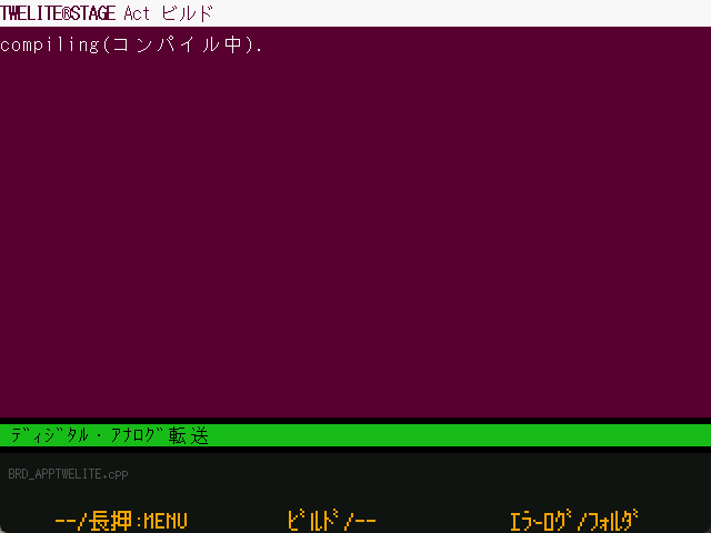
During Build
This is the screen during the build (compile) process. The contents of the build command are output to the console screen. The ... in the middle of the screen indicates the number of files built, and the dark-colored display at the bottom shows the filenames currently being built.
Example of the screen during compilation
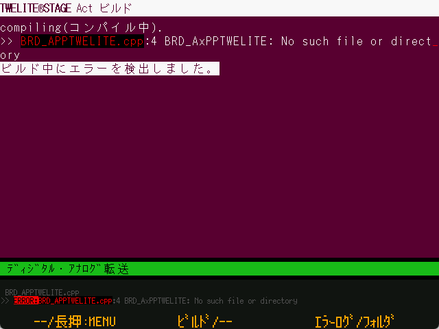
Build Error
If a build error occurs, a screen like the one above is displayed. You can execute a rebuild or display the error log. Also, after a certain timeout, it will return to the previous menu.
Example of error display screen
Only representative error messages are displayed on the screen. When the build fails, there may be cases where the error message is not displayed.
Operation
Description
[ A ]
No assignment
[ A ]Long press
Exit this screen and return to the previous menu.
[ B ]
Rebuild on error.
[ B ]Long press
No assignment
[ C ]
[ C ]Long press
Display the error log (Windows/macOS).The save location is {project folder}/build/builderr.log.
ESC
Exit this screen and return to the write menu.
ENTER
Rebuild on error.
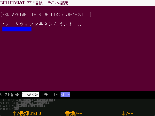
During Write
When the build succeeds, the screen to write the firmware is displayed.
Example of write-in-progress screen
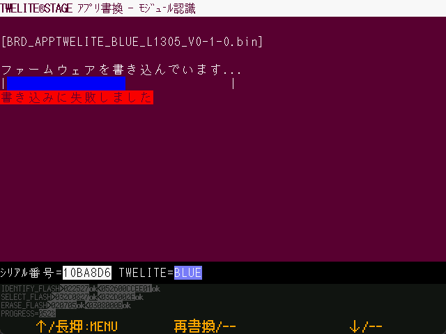
Write Failure
If writing results in an error, a screen like the one below is displayed.
Example of write failure screen
Operation
Description
[ A ]Long press
Exit this screen and return to the selection screen.
[ B ]
Rewrite again(Returns to the previous write menu.Since the menu item is automatically selected,pressing [ B ] again will rewrite.)
ESC
Exit this screen and return to the write menu.
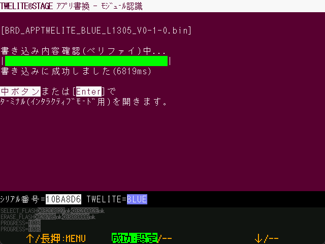
Write Complete
When writing completes successfully, a screen like the one below is displayed.
Example of write completion screen
From version 1.0.2 onwards, after firmware writing, a verify process is performed to read back and confirm the written content.
Operation
Description
[ A ]Long press
Exit this screen and return to the selection screen.
[ B ]
Reset the TWELITE and move to the interactive mode screen (or terminal screen depending on settings).
ESC
Exit this screen and return to the write menu.
1.2.1.2.2.2.3 - Interactive Settings Mode
Using Interactive Settings Mode
Windows
macOS
Linux
RasPi
Overview
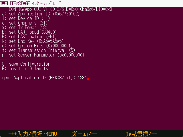
From this screen, you can use the interactive mode of the connected TWELITE.
Example of the Interactive Mode screen
This screen behaves almost the same as a terminal, but adds functions specific to interactive mode, such as operations to transition to interactive mode and detection of exit from it.
The connected TWELITE must have firmware compatible with interactive mode pre-installed.
Since TWELITE input/output is used, if garbled characters occur in serial communication, transitions to and exits from interactive mode may not work as expected.
Mouse operations are not supported. Please use keyboard operations (cursor ↑↓ keys are usable).
You can also transition to and operate interactive mode using the Terminal.
In the terminal, the SET pin operation is not performed automatically. You need to manually set the SET pin to LO.
In the terminal, operations such as entering + + +, Alt(⌘)+I for interactive mode, and module reset Alt(⌘)+R are also defined.
Interactive Mode Screen Operation Flow
Below is an outline of the process flow.
[Set screen background to black]
  ↓
[Reset TWELITE (if controllable, SET=LO)]
  ↓
 --YES--> [Operation screen]
  ↓timeout
[Input '+' three times]
  ↓
 --YES--> [Operation screen]
  ↓timeout
[Operation screen] ※ This state is not interactive mode

[Operation screen]
  ↓
 --> [Exit]
  ↓
 --> [Exit]
  ↓
 ->  --NO-> [Exit]
  ↓            ↓
[Send input string to TWELITE]
  ↓
[Return to operation screen]

[Exit]
  ↓
[Reset TWELITE]
  ↓
[Exit screen] Exit the interactive mode screen and return to the previous screen
1.2.1.2.2.2.4 - Settings of TWELITE STAGE
Settings for TWELITE STAGE APP
Windows
macOS
Linux
RasPi
Overview
From this screen, you can configure various settings of the TWELITE STAGE APP.
Example of the settings screen
The menu on this screen cannot be operated with a mouse.
Also, changing the screen colors may make it difficult to see.
Some menu items explained below may not exist on certain platforms, but all are listed and explained.
Color settings other than the common menu are omitted from the explanation.
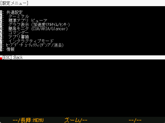
Root Menu
Common
 Terminal
 Standard App Viewer
 Graph Viewer (Acceleration Real-time/Sensors)
 Simple Monitor (CUA/ARIA/Glancer)
 Commander
 Write firmware
 Interactive Settings Mode
Save Data Utilities (Dump/Erase)
Information
Common Settings
a: (      0x00) Startup App Specification
G: (      0x00) Screen Size and Drawing Method
F: (          ) Serial Device ID
f: (0x00FFFFFF) Foreground (Text) Color
b: (0x005A0032) Background Color
B: (    115200) Baud Rate
Setting
Description
Startup App Specification
This setting determines which viewer app to switch to when TWELITE STAGE starts.The setting value is 1..{the number listed in the viewer app menu}.Note: If the serial device ID is not set,the startup will wait for input on the serial device selection screen.
Screen Size and Drawing Method
(Except for M5Stack version) Specified by two characters XY (X: screen size, Y: drawing method).X0:640x480 1:1280x720 2:1280x960 3:1920x1440 4:2560x1440 5:320x240Y0:LCD style 1:CRT style 2:Blur 3:Block
Serial Device ID
(Except for M5Stack version) Set by serial device name or a number 1..9.Note: The number indicates the device enumeration order.
Text Color / Background Color
Specify text and background colors.The common settings color values are inherited by other screens’ settings.If not set on other screens, the common settings colors are used.Colors are specified as 24-bit RGB hexadecimal values but are internally rounded to 16-bit 565 format.
Baud Rate
Set to avoid garbled display in terminals etc. when the TWELITE baud rate is not 115200.
Write Firmware
f: (0x00FFFFFF) Foreground (Text) Color
b: (0x005A0032) Background Color
j: (         0) Number of make jobs at build time
v: (         0) Open a folder with VSCode
l: (         0) Disable LTO
n: (         0) Screen after rewriting is completed
Setting
Description
Number of make jobs at build time
(Except for M5Stack version) Number of parallel jobs during build to shorten build time.Default 0 calculates jobs as (physical processor count - 1).A guideline is to set up to the number of logical processors.
Open a folder with VSCode
(Requires VSCode installation) Setting 1 opens folders using the code command (VSCode) instead of the OS standard folder window.The executable TWELITE_Stage_VSCode defaults to 1.
Screen after rewriting is completed
(Except for M5Stack version) Setting 1 opens the terminal instead of the interactive mode screen.Setting 2 returns to the rewrite menu.TWELITE_Stage_VSCode sets this to 2.
Disable LTO
(Windows only) Setting 1 disables LTO in the Windows compiler.LTO produces smaller binaries but takes longer to link.Disabling LTO results in faster linking.
Save Data Utilities
r: Read sector.
R: Read ALL sectors.
e: Erase sector.
E: Erase ALL sectors.
This screen is a utility for maintaining data save areas. It emulates EEPROM (64 bytes per sector, up to 60 sectors, 3840 bytes).
Setting
Description
r
Reads a sector.Input 0..59 to display the contents of the specified sector.
R
Input YES to read all sectors, but only the tail part is displayed.
e
Erases a sector (0xFF).Input 0..59 to erase the specified sector.
E
Input YES to erase all sectors.
On Windows, macOS, Linux, and Raspberry Pi, data is saved in {executable name}.sav (default TWELITE_Stage.sav file).
1.2.1.2.2.2.5 - Select SERIAL port
Select SERIAL port menu
Windows
macOS
Linux
RasPi
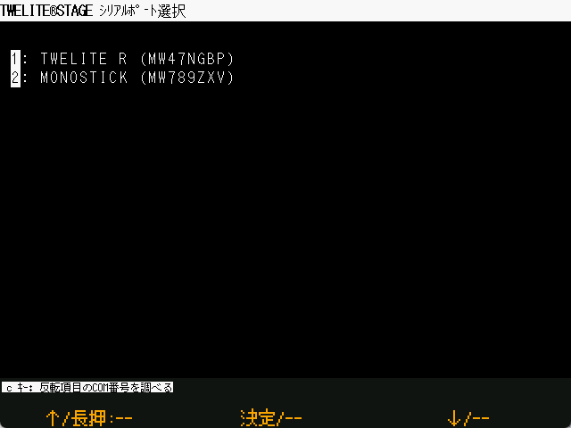
Overview
On this screen, you can (re)select the serial port.
Example of the serial port selection screen
Instead of using this screen, you can also switch the serial port with Alt(⌘)+0, Alt(⌘)+1,2,...
1.2.1.2.3 - Logging Function
Logging function between TWELITE and PC
Windows
macOS
Linux
RasPi
You can record serial communication logs between TWELITE and PC.
Operation
Start Recording
Press Alt(Cmd)+L.
Example of the log start screen
Stop Recording
While recording, press Alt(Cmd)+L again.
Example of the log stop screen
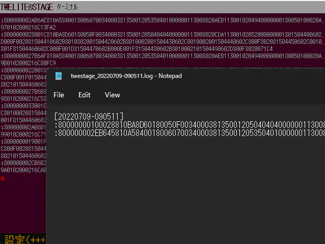
The log recording will stop, and the log file at that point will be opened using the OS default application (Notepad on Windows, Console.app on macOS).
On Raspberry Pi, only saving the log file is performed. There is no function to automatically open the log file.
Specifications
Log Recording
Strings received from TWELITE are recorded as-is.
Strings sent to TWELITE are recorded one character at a time.
On Windows, they are enclosed in 「 」, and on macOS / Linux / Raspberry Pi, they are enclosed in « ».
For example, «t» means that the character t was input from the keyboard.
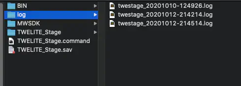
Log Folder and File Name
Logs are saved in the {folder where the TWELITE STAGE APP executable is located}/log folder, with a file name based on the start date and time of the logging.
Press Alt(Cmd)+Shift+L to open that folder.
Example of the log output folder
1.2.1.3 - Detailed Specifications
Detailed specifications of TWELITE STAGE APP
1.2.1.3.1 - Detailed Settings with Command-line Arguments and ini Files
Detailed settings for TWELITE STAGE APP using command-line arguments and ini files
Command-line Arguments
Command-line arguments configure some detailed settings of the TWELITE STAGE APP.
Command-line Argument
Description
-E 0
Disables graphical effects such as fade-out.
-R {type}
Sets the rendering type with the {type} value.0: Default1: OpenGL2: DirectX (Windows) Metal (macOS)3: Software
-J
Enables the game controller.
-x {x_pos},-y {y_pos}
Sets the position of the TWELITE STAGE App graphical window at startup.{x_pos} and {y_pos} are the screen coordinates of the top-left corner of the window.
ini Files
ini files are used to configure basic settings of the TWELITE STAGE APP (such as referencing the MWSDK folder).
The ini file name is {base name of the TWELITE STAGE APP executable} + .ini. Usually, it is TWELITE_Stage.ini.
;;; Change the MWSDK reference.
; MWSDK=MWSDK
mwsdk=mwsdk2020_10

;;; Interface language
; LANG=en

;;; Window geometry
GEOM_X=200
GEOM_Y=100
Syntax
ini files are written as plain text files.
Keys and values are stored on a single line separated by = (e.g., KEY=value).
The key and value strings start at the beginning of the line (no spaces or other characters allowed before the key).
Spaces are not allowed between the key and the value.
Comment lines start with ; or # at the beginning of the line.
Settings
Key
Value
MWSDK
Changes the MWSDK folder. The default folder is MWSDK located in the same folder as the TWELITE STAGE APP executable. If you need to use an older or custom MWSDK, you can specify the folder name here.
LANG
LANG=en changes the user interface language from the default (Japanese) to English. This setting is carried over to the make parameter (TWE_LANG_PREF) and is reflected in the interactive mode display language setting of some firmware (apps) such as TWELITE_Apps.
GEOM_X, GEOM_Y
Changes the location where the TWELITE STAGE App window appears.
Running TWELITE STAGE APP with Different Settings
If you need different settings for the TWELITE STAGE APP, copy the executable to the same folder as the TWELITE STAGE APP and create an .ini file with the same name.
For example, to use the English interface, copy TWELITE_Stage.exe (note: .exe is the Windows executable extension) to TWELITE_Stage_en.exe and write the setting LANG=en in TWELITE_Stage_en.ini to create an executable with the English interface enabled.
  TWELITE_Stage.exe
  TWELITE_Stage.ini | No special settings

  TWELITE_Stage_ja.exe | Copy of TWELITE_Stage.exe
  TWELITE_Stage_en.ini | LANG=en is set.
1.2.1.3.2 - Environment Variables
Environment variables used by TWELITE STAGE APP
TWELITE STAGE APP internally sets environment variables to operate build programs such as make. There is no need to set environment variables beforehand.
Environment Variables Set Internally
Environment Variable
Description
MWSDK_ROOT
By default, the MWSDK folder located in the folder where the TWELITE STAGE APP executable is stored (that is, ../MWSTAGE/MWSDK) is specified. If MWSDK.ini is specified, the specified folder name is adopted.
MWSDK_TWENET_LIBSRC
For sample code and TWELITE APPS source code folders, definition files for Microsoft Visual Studio Code (VS Code) are pre-created. In these definition files, the library source code reference path is specified for code interpretation within the VS Code editor, and this environment variable is used for that purpose.If the MWSDK_TWENET_LIBSRC environment variable is properly set, code interpretation will work even in project folders outside of MWSDK, enabling features such as function name completion for the library. (Reference)
LANG=C
Explicitly set to make the toolchain messages appear in the default language (English).
PATH
On Windows, adds the PATH to the SDK-included msys utilities.
Used in VS Code configuration definitions. JOBS: Passes the number of parallel builds set in STAGE APP DISABLE_LTO: Disables LTO (
Windows
) LANG_PREF: The display language (JP: Japanese, EN: English) of the TWELITE STAGE APP is set.This setting is also inherited by the parameter (TWE_LANG_PREF) of make at build time.
Reference
Excerpt from .vscode/settings.json configuration example:
Definitions starting with "../../" are unnecessary when opening a project from the TWELITE STAGE app. These specify source reference paths in the default folder structure when the environment variable MWSDK_TWENET_LIBSRC is not set.
1.2.1.3.3 - Adding Project Descriptions with 000desc.txt
How to add project descriptions using 000desc.txt
When you create a 000desc.txt file in the project folder, TWELITE STAGE APP displays its contents in the project folder list.
Example display of 000desc.txt
The file should be written as plain text in UTF-8 format. There are two formats as follows.
Format 1
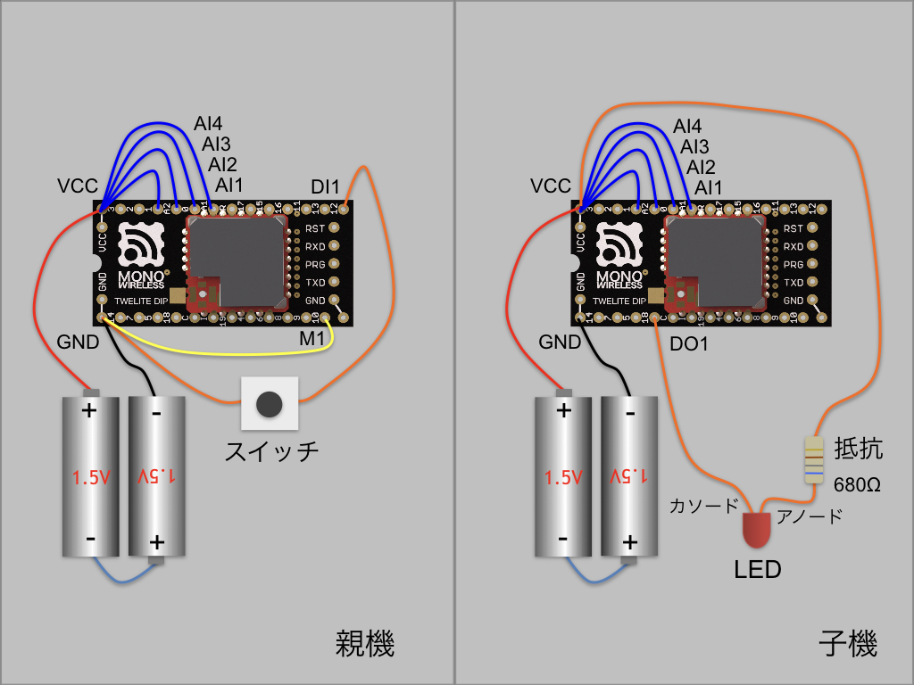
LED lights up when the switch is pressedact4 operates an act that lights up the LED when the switch connected to TWELITE DIP is pressed.https://mono-wireless.com/jp/products/act/index.html
The first line is the title line.
The following lines describe details.
If the last line starts with http, it becomes a link to a website.
Format 2
[JAPANESE]TITLE=act templateDESC=This file contains only empty setup() and loop() functions.Please use it to write a new act.URL=jp/MWX/content/Act_samples/README.html[ENGLISH]TITLE=act empty templateDESC=This act file only contains empty setup() and loop(),which is intended to write a new act.URL=en/MWX/content/Act_samples/README.html
This format is like an ini file. The item name starting from the beginning of the line and the = character define the item, and the content after = is the item’s content.
Item Definition
Details
[JAPANESE], [ENGLISH]
Block separators
TITLE=
Title line
DESC=
Description. Can include multiple lines with line breaks.
URL=
Link to a website or file
About URL specification
URL=
Details
Starting with https:, http:
Opens that address
Others
Specify a relative folder based on {MWSDK_ROOT}/docs/.If set as a/b/c.html, it is converted to {MWSDK_ROOT}/docs/a/b/c.html.
1.2.1.4 - License
About the license
The executable format of TWELITE_Stage distributed by Mono Wireless Inc. is subject to MW-SLA-1J,1E.
The source code is subject to MW-OSSLA-1J,1E. Please refer to the linked page for an overview.
If you build from the source code, operation under MW-OSSLA-1J,1E, which has more relaxed restrictions for non-commercial purposes, is possible.
Some distribution packages (as of 2020/10/9, only the M5Stack 0.8.9a package) apply a dual license of MW-SLA-1J,1E and MW-OSSLA-1J,1E. Please check the license description within the package.
Please note that for commercial use, you will need to select MW-SLA-1J,1E.
Open Source Components Used
We appreciate the open source projects that provided high-quality source code.
Name
Description
SDL2
Simple DirectMedia Layer Copyright (C) 1997-2020 Sam Lantinga
getopt
Copyright (c) 1987, 1993, 1994 The Regents of the University of California. All rights reserved.
regex
regex - Regular expression pattern matching and replacement By: Ozan S. Yigit (oz) Dept. of Computer Science York University
Depending on the platform, the latest version distributed and the latest version in the revision history may not match.
The latest version of the source code may not be registered at the above sites.
2.4.4 MWSTAGE2025_07 Release
Major Version Upgrade
Added support for TWELITE STICK
Enhanced serial port functionality
Added baud rate switching via ALT+B
Connection status now displayed in the title bar
Makefile error message handling
Extracts the message part ... from errors output in the format $(error <MWERRM>...</MWERRM>)
These error messages are intended to be used when attempting to build projects for unsupported architectures (e.g., GOLD only, or BLUE/RED only)
Support for language setting in interactive mode
Interactive mode language can now be specified at build time via TWE_LANG_PREF=(JP|EN)
When launching external tools (e.g., VSCode), the MWSDK_MAKE_LANG_PREF environment variable is now set
2.4.3
For projects with multiple configuration types located in subfolders (and not directly under the root build), folder listing is now limited to only those that contain a build/ directory, preventing unnecessary folders from being shown
Fixed a crash that occurred when error messages were too long during build errors
Changed the order of serial protocol checks for determining BLUE/RED/GOLD: now tries GOLD first (for GOLD-targeted SDK)
2.4.2
Added support for interactive mode transition control using the SET pin (CTS pin on MONOSTICK)
Behavior in TWELITE_Apps is as follows:
If SET pin is held for less than ~100ms → normal boot (prevents accidental interactive mode entry due to noise)
If held longer than the above → enter interactive mode on boot
If held for ~3 seconds or more → erase entire EEPROM on startup
Each app is informed of the interactive mode transition via a startup parameter
Apps receiving this parameter will, in principle:
Skip app-specific initialization
Skip interrupt handler setup, etc.
Automatically start interactive mode on UART0 at 115200 8N1
Suppress exit from interactive mode via +++
Under this spec, the STAGE app behaves as follows:
For regular transition to interactive mode, hold the SET pin for about 300ms
When holding [ C ] on the interactive mode guidance screen, SET pin is held for about 5 seconds
If Entering Interactive ... message is not received within timeout, fallback to trying +++ as per previous behavior
Additional code cleanup
2.4.1
Initial support for TWELITE GOLD
If a control command response from GOLD is received at startup, it’s recognized as GOLD; if it fails, control commands for the BLUE/RED series are attempted instead
1.3.8 MWSTAGE2022_08 Included Version
Major version upgrade.
Changed internal rendering resolution from 320x240 to 640x480 pixels
Added real-time graph for accelerometer sensor
Added sensor graph that saves sensor data and displays graphs
Supported English display
Changed main manuals to local HTML files
1.0.8 MWSTAGE2021_09 Included Version
There was a case where buttons [ A ] [ B ] [ C ] remained pressed even after the pointer moved away
STAGE APP sends CRLF to TWELITE when Enter is input
Updated Mac FTDI library to allow operation without serial intermediary program on Apple Silicon (M1)
Internally set PATH for msys toolset on Windows to prevent unexpected make calls
Allowed moving to the writing screen even if TWELITE is not connected (input B,R keys and specify the target TWELITE model)
When configured to use VSCode, selecting act or TweApps opens the writing screen for .bin files under build/ without building (build is done from VSCode)
Internally set several environment variables so that VSCode launched from TWELITE STAGE can refer to them, enabling proper builds and library resource referencing in VSCode
Sample code is stored under MWSDK folder, but dropping a folder for build target allows build and write operations for folders other than MWSDK (folder names must not contain spaces or Japanese characters)
Displayed internal folder settings and environment variable settings on the console screen at startup
Waited 1 second before exiting STAGE APP on termination
1.0.7pre2
Enhanced support for Raspberry Pi (1.0.7pre2)
Support for serial0 (TWELITE STAGE HAT)
Added build for Zero (build with supported libraries & disabled rendering fade feature)
Added build for X11 desktop
Made it usable with general FTDI devices (FT232, FT230). Firmware writing mode must be done manually
Added feature to display COM ports assigned in Windows by pressing c key on serial port selection screen
Allowed changing baud rate from 115200bps
Added command line option (-E 0) to disable rendering fade feature.
1.0.3 MWSTAGE2020_12 Included Version
Supported TWELITE CUE (parser and CUE viewer)
Enabled verification (comparison) during writing in the rewrite menu
Provisional support for Apple Silicon (TWELITE_Stage.command is a universal app; external command sersrv_ftdi.command and Tools are rebuilt Intel binaries runnable with Rosetta2; serial communication is slower due to external command)
Moved MWSTAGE/MWSDK/Tools to MWSTAGE/Tools (to allow direct use of MWSDK_COMMON repository)
TWELITE_Stage.ini (removes extension from startup filename and adds .ini) is loaded at startup to allow selecting MWSDK folder (makes it easy to switch old library sets)
Updated SDL2 library for screen rendering to 2.0.12 (Windows, MacOS, RaspberryPi)
Static build on Windows with no DLL files required
Set parallel build count for make -j to (number of physical CPUs - 1)
Explicitly reopened serial port in several places in rewrite menu to improve recovery when USB connection is disconnected due to device removal
When opening mwx or twesettings with Alt(Cmd)+Shift+m, t, opens folders listed in TWENET/usever.mk
Fixed issue where writing menu transition failed on first startup at /dev/serial0 on Raspberry Pi
Known Issues
Help message when pressing Alt(Cmd) at startup may not appear; can be shown by inputting Alt(Cmd)+0
Line wrapping may be broken when filenames are too long in rewrite menu
Apple Silicon operation has not been sufficiently tested
0.9.11 MWSTAGE2020_10, Raspberry Pi Version (Provisional)
(* This version is not comprehensively tested *)
Operation on Raspberry Pi
Other feature adjustments
0.9.9 - MWSTAGE2020_10 Included Version
Added [Web] button to the top-level menu to open related links in browser
Implemented folder, web, and VS Code open features for Linux version
Sometimes difficult to transition to writing menu when TWELITE frequently outputs UART
M5Stack version made dual-licensed for MW-SLA-1J,E / MW-OSSLA-1J,E and updated readme-j.txt.
0.9.8
Added [Web] button to viewer list to open related sites.
Revision Details
Added Commander to viewer
Standard app 0x80 command
NOTICE PAL LED control (send commands to App_Wings)
NOTICE PAL support for viewer > PAL viewer
Added menu for Act_extras
More advanced than Act_samples
Uses external open source libraries (e.g. sensor procedures)
Expanded mouse operation (lists, buttons, tabs)
Focus on mouse move, confirm with left click, right click inputs [ESC] key
Reduced screen rendering load
Disabled screensaver when app is in background
Reduced rendering frequency when app is in background to lower CPU load
Enhanced build project list (act, TWE_Apps, Act_extras)
Show summary at bottom when selecting items (reads 000desc.txt, processed by TWE_Desc class)
Ability to open project folder (or open in VSCode)
Ability to open related websites
Open mwx library with Alt+Shift+m and twesettings library with Alt+Shift+t
Open selected folder or build error files in build menu
Added logging (serial port input/output)
Start/stop log with (Alt/Cmd+L)
Log files saved in {folder containing TWELITE_Stage executable}/log
Filename format: twestage_{date-time}.log
Open log file folder with Shift+Alt/Cmd+L
Other changes and fixes
Changed display method for serial (FTDI) device names and IDs
Fixed issue where App_UART did not transition to interactive mode
Changed behavior on folder drop (previously sometimes triggered binary write, now transitions menu)
On terminal long press [C], clears screen in addition to reset
Known Issues
M5Stack may hang and reset settings to default when saving settings
0.8.9
2020_05 Release Version
Added window icon
Relaxed maximum list constraints on BIN file list screen (win/linux/mac)
Added Glancer viewer
Adjusted explanatory text
Adjusted console screen rendering
Fixed issue where setting destination screen after firmware write (interactive mode or terminal) did not work
Changed assignment of Alt(or Cmd)+W
Other bug fixes
0.8.6
Initial release of Linux version
0.8.5
Initial release
1.3 - TWELITE APPS
Ready-made software for signal transmission and serial communication, ready to use without software development.
TWELITE APPS - Twilight Apps are ready-made software for TWELITE that can be used as is without software development.
What is Interactive Mode
Interactive mode is the mode to perform detailed settings of TWELITE APPS.
You can make necessary settings when you want to communicate with multiple groups or reduce communication errors.
Connection with PC
For TWELITE
For MONOSTICK
Attach the TWELITE R series to the 7P interface prepared on the parent board and connect to the PC using a USB cable.
Connect the MONOSTICK to the PC’s USB port. TWELITE R series is not required.
Connection between TWELITE (SMD) and PC
Connection between MONOSTICK and PC
For TWELITE DIP (BLUE/RED)
For Others
Attach to TWELITE R series and connect to the PC using a USB cable.
For TWELITE series with 7P interface, attach TWELITE R series and connect to the PC using a USB cable.
Connection between TWELITE DIP (BLUE/RED) and PC
Connection between other TWELITE series and PC
Switching to Interactive Mode
Interactive mode cannot be used while TWELITE is in sleep mode.
When Using TWELITE STAGE
TWELITE STAGE APP is an integrated development tool that includes firmware writing and configuration of TWELITE, as well as a function to display received data.
TWELITE STAGE APP is included in TWELITE STAGE SDK. Please download TWELITE STAGE SDK.
Launch terminal software on the PC (communication settings: 115200bps/8-N-1)
Reset TWELITE.
Slowly press the + key on the PC keyboard three times (interval 0.2 to 1 second). If it does not work well, keep entering + repeatedly.
To exit interactive mode, press + three times again.
Entering the + key from the numeric keypad may fail. Please use the main + key on the keyboard.
Operation of Interactive Mode
Interactive mode displays a screen like the following.
--- CONFIG/TWELITE APP V1-00-2/SID=0x81000038/LID=0x78 ---
 a: set Application ID (0x67720102)
 i: set Device ID (--)
 c: set Channels (18)
 t: set mode4 sleep dur (1000ms)
 y: set mode7 sleep dur (10s)
 f: set mode3 fps (32)
---
 S: save Configuration
 R: reset to Defaults
The displayed content varies depending on the firmware type and version.
Terminal software that does not support escape sequences may display incorrectly.
Steps
Select value: press the first letter alphabet
Specify value: input the value
Confirm value: press Enter
Save value: press S (uppercase)
Apply value: restart TWELITE
Values in parentheses indicate the current setting.
Pressing R (uppercase) resets to default values (apply with S).
Example of Operation
To set the Application ID to 0xBEEFCAFE, input as follows:
Input Application ID (HEX:32bit): BEEFCAFE
To apply the settings, save the content with the S command and then restart the device.
Common Settings for TWELITE APPS
Frequency channel, application ID, device ID, retry count, and transmission output settings are common to TWELITE APPS.
Application ID and Frequency Channel
Image of Grouping
Devices must have the same application ID and frequency channel to communicate.
a: Application ID
Setting the same value to all devices communicating allows logical network separation.
TWELITE discards packets received from devices with different application IDs. Therefore, multiple groups can be established within the same frequency channel.
Even if the application ID is the same, if the frequency channel is the same, packet interference cannot be avoided. Please separate frequency channels as much as possible.
If the number of groups is 16 or less, it is recommended to separate both frequency channels and application IDs for each group.
Values with consecutive 0 or F in the upper or lower 2 bytes cannot be set (0xFFFF????/0x0000????/0x????FFFF/0x????0000).
When setting values equal to or greater than 0x80000001, be sure to use the serial number engraved on your TWELITE device.
As long as everyone follows this rule, everyone can obtain a unique application ID.
c: Frequency Channel
Setting the same value to all devices communicating allows physical network separation.
TWELITE conforms to the IEEE802.15.4 standard and divides the 2.4GHz band into 16 channels.
List of Frequency Channels
To change the frequency channel, press c (lowercase).
Use of Channel Agility (usually not recommended)
Operation Image
By specifying multiple channels separated by commas, channel agility can be enabled.
Channel agility improves communication success rate in poor communication environments by switching multiple frequency channels at regular intervals during communication.
Up to 3 channels can be specified simultaneously. The specified channels are switched in order at regular intervals for transmission. The receiver also switches channels in order at regular intervals for reception.
Reception is not possible during channel switching. In normal communication environments, reliability is lower than specifying a single channel. Since the number of transmissions from the child device needs to be increased, it is a wasteful method in terms of battery consumption. However, use it when you want to handle situations where certain channels become completely unusable. Normally, it is recommended to specify a single channel after identifying a channel with less interference in advance.
Default Values for Each TWELITE APP
TWELITE APPS
Application ID
Frequency Channel
Super Simple! Standard App (App_Twelite)
0x67720102
18
Remote Control App (App_IO)
0x67720107
16
Serial Communication App (App_Uart)
0x67720103
18
Wireless Tag App (App_Tag)
0x67726305
15
Pulse App (App_PAL)
0x67726305
15
Queue App (App_CUE)
0x67720102
18
Aria App (App_ARIA)
0x67720102
18
Parent/Relay App (App_Wings)
0x67720102
18
i: Logical Device ID
The logical device ID is used to identify each device. You can assign logical IDs to each device.
Image of Assigning Logical Device ID
When using multiple child devices for one parent device, assign different IDs (1 to 100) to each child device.
There is a reported bug with the TWELITE STAGE 202508 Japanese interactive mode compatible version for TWELITE BLUE/RED (binaries with *J, not GOLD version) where the logical device ID value cannot be changed in some cases.
The cause is under investigation. Please use the English version without the *J suffix.
x: Transmission Output and Retry Count
You can weaken the transmission output to narrow the effective radio transmission range. However, power consumption does not change, so normally use the maximum output.
Weakening the output may cause the signal not to reach when needed.
If you need to weaken the output to narrow the reach, it usually indicates a problem in system design. Please properly separate the network by frequency channel and application ID.
Retry count refers to the number of additional transmissions per one transmission request. Setting retry count may improve data arrival rate in poor communication environments. However, communication time and power consumption increase accordingly.
In interactive mode, input a two-digit number.
Tens place: retry count
1 to 9 times
0 is the default value for each app
F disables retry
Ones place: transmission output
3 is the strongest
2/1/0 each step down reduces output by -11.5dB
Examples
32 → Retry 3 times, output one level weaker
93 → Retry 9 times, maximum output
The theoretical transmission distance is 6dB. The transmission distance is expected to be about one-fourth when output is reduced by one level. However, actual distance depends on noise and obstacles.
Resetting Settings
Some settings may interfere with operation (such as baud rate changes).
For settings that differ between apps, please see the following pages.
1.3.1 - TWELITE APPS (Unified) Manual
Unified firmware that consolidates all TWELITE APPS
Mainly for the TWELITE GOLD series, this firmware integrates TWELITE APPS such as the Extremely Simple! Standard App App_Twelite, allowing functionality to be switched without rewriting.
1.3.1.1 - TWELITE APPS (Unified) Manual
Latest Edition
TWELITE_Apps is a firmware that integrates TWELITE APPS such as the Extremely Simple! Standard App App_Twelite, allowing users to switch functionalities without rewriting. It’s like an assortment pack of TWELITE APPS.
It comes pre-installed on TWELITE STICKs at the time of shipment.
Overview
The unified firmware bundles the following TWELITE APPS:
A menu like the following will display a list of TWELITE APPS:
[TWELITE AppSel/v0-02-1/SID=8300051A/SAVE=04-12-01]
M: AppSel           App selector (this screen)
R: Revert to DEFAULT(*DEF)
A: App_Twelite      Standar app. (App_Twelite)
B: App_IO           App for remote. (App_IO)
C: App_UART         App for SERIAL comm. (App_Uart)
D: App_Wings        Parent/Repeater (App_Wings)(*DEF)
E: App_OTA          OTA Apps for ARIA/CUE.

[!]:Reset [R]:Revert [$]:LANG=English
3. Select a TWELITE APP
Just like in Interactive Mode, you can switch to a TWELITE APP by entering the command ID letter.
For example, in the above example, entering C switches to App_Uart.
[App_UART / App for SERIAL comm. (App_Uart)]
Designed for UART (Serial) communications. UART is commonly used on MCUs.

=== Please select from the list below. Save the startup application. ===
1: Normal
2: for TWELITE UART

[BS]:Back
On the switching screen, select a variation if necessary.
After that, the TWELITE APP will switch and reset immediately.
Initialize TWELITE APP
On the TWELITE APP list screen, entering R will revert to the default TWELITE APP.
! Clear Save Data? The next key will perform:
S: Clear App Selection.
!: Clear ALL SAVE DATA.

[BS]:Back
If you enter S, only the switch will occur. If you enter !, the settings will also be initialized along with the switch.
1.3.2 - Extremely Simple! Standard App Manual
Transmission of digital and analog signals
The input/output states of parent and child devices are synchronized.
An all-in-one package supporting 4 digital ports, 4 analog ports, serial, and I2C.
Simplified with versatile features, but does not focus on processing speed, responsiveness, or power saving.
Sends input status to parent every 10 seconds, and disables reception to always enter power-saving mode
✅
127
O: Not connected (OPEN), G: Connected to GND
Initial state is Child: Continuous mode.
The initial Logical Device ID (LID) used to identify the device varies depending on the mode.
Only in Parent or Repeater modes, the LID can be switched via Interactive Mode.
Please use 121 for Parent and 122 for Repeater.
Handling of unused AIx ports
In Child: Continuous / Child: Continuous 0.03s / Parent: Continuous modes, please connect unused AIx ports to VCC.
Unused AIx ports report undefined values. These modes send data when there is a change in input signals, which may cause unnecessary data transmission.
Parent Device
Continuous Mode
Parent: Continuous Mode
When input signals change or every 1 second, data is sent to all child devices.
It always waits for data sent from child devices, providing good responsiveness but continuously consuming power.
Reception: Always waiting
Transmission: On input change / every 1 second
Disabling periodic transmission
You can disable periodic transmission every 1 second by setting option bit 0x00000002 in Interactive Mode.
Child Device
Continuous Mode
Child: Continuous Mode
When input signals change or every 1 second, data is sent to all parent devices.
It always waits for data sent from parent devices, providing good responsiveness but continuously consuming power.
Communication image with parent device
Reception: Always waiting
Transmission: On input change / every 1 second
Disabling periodic transmission
You can disable periodic transmission every 1 second by setting option bit 0x00000002 in Interactive Mode.
Child: Continuous 0.03s Mode
This mode shortens the periodic transmission interval of Child: Continuous Mode from 1 second to 0.03 seconds.
Although it always waits for data sent from the parent, the communication from child to parent occupies the bandwidth, making the parent’s input response slower. It continuously consumes power.
Communication image with parent device
Reception: Always waiting
Transmission: On input change / every 0.03 seconds
Because a single child occupies most of the bandwidth, please avoid using multiple children simultaneously as much as possible.
Intermittent Mode
Child: Intermittent 1s Mode
When input signals change or every 1 second, power-saving mode is canceled and data is sent to all parent devices.
Reception is disabled, so control from the parent device is not possible. This mode has excellent power-saving performance.
Communication image with parent device
Reception: Disabled
Transmission: On input change / every 1 second
Child: Intermittent 10s Mode
When input signals change or every 10 seconds, power-saving mode is canceled and data is sent to all parent devices.
Reception is disabled, so control from the parent device is not possible. This mode has excellent power-saving performance.
Communication image with parent device
Reception: Disabled
Transmission: On input change / every 10 seconds
Child: Intermittent Reception 1s Mode
When input signals change or every 1 second, power-saving mode is canceled and data is sent to all parent devices.
Reception is also performed every 1 second. It has excellent power-saving performance but is inferior to Child: Intermittent 1s Mode.
Communication image with parent device
Reception: Every 1 second
Transmission: On input change / every 1 second
Because reception is intermittent, the parent device must operate continuously.
Repeater
Continuous Mode
Repeater: Continuous Mode
The repeater forwards received packets.
Up to three repeaters can be installed between parent and child devices, but increasing repeaters increases the number of packets, which may cause interference.
Image of relaying
Reception: Always waiting
Transmission: On reception
You can also add repeater functionality to child devices. Specify 0x00008000 in the option bits of Interactive Mode.
1.3.2.1.3 - Alternative Baud Rate Setting for Extremely Simple! Standard App
Changing the baud rate used for UART communication
The Extremely Simple! Standard App (App_Twelite) uses 115200 bps as the default baud rate for UART communication, but this can be changed.
Enabling Alternative Baud Rate Setting
You can enable the alternative baud rate setting by connecting the BPS pin to GND.
The baud rate setting in Interactive Mode indicates the alternative baud rate. If the BPS pin is not connected to GND, the Interactive Mode setting will not be applied.
Interactive Mode uses UART communication. When switching the baud rate of TWELITE, you must adjust the PC side baud rate before using Interactive Mode (Settings in TWELITE STAGE App).
1.3.2.1.4 - UART Function of Extremely Simple! Standard App
Data format used in UART function
This explains the data format used in the UART function of the Extremely Simple! Standard App (App_Twelite).
Digital and Analog Input/Output
0x81: Status Notification from Remote Device
Outputs the state of the received input signals.
Data Format
#
Data
Content
Note
char
Header
: only
0
uint8
Source Logical Device ID
1
uint8
Command Number
0x81 only
2
uint8
Packet Identifier
Generated from Application ID
3
uint8
Protocol Version
0x01 only
4
uint8
LQI
0-255
5
uint32
Source Serial ID
0x8???????
9
uint8
Destination Logical Device ID
10
uint16
Timestamp
64 counts per second
12
uint8
Relay Count
13
uint16
Power Supply Voltage
Unit is mV
15
int8
-
(Unused)
16
uint8
Digital Signals
Corresponds to DIx from LSB, 0 is High MSB 1 means periodic transmission
Parent 0x00, Child 0-0x7F, All Children 0x78, Self 0xDB
1
uint8
Packet Identifier
0x88 only
2
uint8
Response Number
Number output to response message
3
uint8
Command Number
Write 0x1, Read 0x2, Read/Write 0x4
4
uint8
I2C Address
7-bit
5
uint8
I2C Command
First command byte
6
uint8
Data Size
0 means none
7
[uint8]
Data
Byte sequence of length \(N\)
uint8
Checksum
LRC8
char
Footer
CR (0x0D/'\r')
char
Footer
LF (0x0A/'\n')
For command number 0x4, specify the data size to read and omit the data. The specified I2C command is written, and the specified amount of data is read.
0x89: I2C Output
Data Format
#
Data
Content
Note
char
Header
: only
0
uint8
Source Logical Device ID
Parent 0x00, Child 0-0x7F, All Children 0x78, Self 0xDB
1
uint8
Packet Identifier
0x89 only
2
uint8
Response Number
Number output to response message
3
uint8
Command Number
Write 0x1, Read 0x2, Read/Write 0x4
4
uint8
Result
Failure 0, Success 1
5
uint8
Data Size
0 means none
6
[uint8]
Data
Byte sequence of length \(N\)
uint8
Checksum
LRC8
char
Footer
CR (0x0D/'\r')
char
Footer
LF (0x0A/'\n')
1.3.2.1.5 - Interactive Mode (Extremely Simple! Standard App)
Detailed configuration changes via Interactive Mode
You can perform detailed configuration of the app via Interactive Mode.
This section explains functions specific to the Extremely Simple! Standard App (App_Twelite). For common features, please refer to the TWELITE APPS manual top page.
Interactive Mode cannot be used while TWELITE is sleeping.
Set the Mx pin settings to Child Continuous Mode or Parent/Relay Mode.
Display Example
The following screen is displayed.
--- CONFIG/TWELITE APP V1-08-2/SID=0x8201001f/LID=0x78 ---
 a: set Application ID (0x67720102)
 i: set Device ID (--)
 c: set Channels (18)
 x: set Tx Power (03)
 t: set mode4 sleep dur (1000ms)
 y: set mode7 sleep dur (10s)
 f: set mode3 fps (32)
 z: set PWM HZ (1000,1000,1000,1000)
 o: set Option Bits (0x00000000)
 b: set UART baud (38400)
 p: set UART parity (N)
---
 S: save Configuration
 R: reset to Defaults
Overrides the intermittent interval of the child intermittent 1-second mode from 1 second to another value. Unit is milliseconds.
Setting 0 disables periodic wakeup by timer. In this case, wakeup occurs on falling edge of DIx but not on rising edge.
y: Child Intermittent 10-second Mode Interval
Overrides the intermittent interval of the child intermittent 10-second mode from 10 seconds to another value. Unit is seconds.
Setting 0 disables periodic wakeup by timer. In this case, wakeup occurs on falling edge of DIx but not on rising edge.
f: Child Continuous 0.03-second Mode Cycle
Overrides the number of transmission requests per second from 32 times to 4/8/16 times. Retry count is not included.
z: PWMx Frequency
If one value is specified, it overrides the frequency of all PWM ports. If specified by comma separation, individual values for PWM1 to PWM4 can be overridden.
o: Option Bits
Specify a 32bit number. Enables settings linked to each bit.
Overrides the alternative baud rate selected when the BPS pin is connected to GND at startup from 38400bps.
Values can be selected from 9600/19200/38400/57600/115200/230400. Specifying other values may cause errors.
This setting is not applied when the BPS pin is left open at startup. The baud rate is fixed at 115200bps.
This is a specification to prevent situations where Interactive Mode becomes unusable due to baud rate changes.
p: UART Parity
N means no parity, O means odd parity, and E means even parity.
Data bits are fixed to 8, stop bits to 1. Hardware flow control cannot be set.
Details of Option Bits
Explanation of settings linked to each bit of the Option Bits value.
00000001: Low Latency Mode
Low Latency Mode shortens the delay on the receiver side by quickly transmitting after detecting changes in DIx.
Low Latency Mode Operation
In the initial state, there is a delay of about 30-70ms until DIx is reflected on DOx. Low Latency Mode shortens this delay to about 3-10ms by simplifying processing to avoid chattering and wireless packet interference.
Falling edge detection uses interrupts
After detection, no new detection occurs for about 100ms
Rising edge detection uses periodic judgment
Transmission occurs if 5 consecutive readings are High at 1ms intervals
(Initially, transmission occurs if 5 consecutive readings are High at 4ms intervals)
No transmission or retransmission delay is set at detection; the wireless packet is immediately sent
Typical delays are about 3-5ms for falling edges and about 10ms for rising edges
Actual delay varies due to transmission/reception failures, etc.
In intermittent mode, the time from wakeup to transmission is also shortened
00000002: Disable Periodic Transmission
Disables periodic transmission every 1 second in continuous mode for child devices.
00000004: Disable Periodic Transmission and UART Output
For child devices: disables periodic transmission every 1 second in continuous mode and stops UART output of received data.
00000010: Disable Transmission on AIx Change
For child devices: disables transmission when AIx input changes in continuous mode.
Since released AIx ports report undefined values, connect them to VCC when analog input is not used. This option allows omission of connection to VCC.
00000020: Disable AIx Value
Sends packets treating unused ports as 0xFFFF without using ADC measurement values.
00000040: Change PWMx Calculation Formula
By default, adjusted output for volume control is applied to PWMx.
This option disables that and outputs full scale for inputs below 1.8V.
Duty Cycle Calculation Formula
Duty cycle \(duty\) can be expressed using input voltage \(V_{input}\) and power supply voltage \(V_{cc}\) as in (1).
1.3.3.1.1.1.1.4.3 - Output from Aria App (Parent and Repeater App)
Output format when data is received from the Aria app
TWELITE ARIA Mode
Previously, instructions on how to interpret data using Python were provided here, but now the official library is distributed.
Please use MWings for Python.
1.3.3.1.1.1.1.4.4 - Details of Output from Pal, Cue, and Aria Apps (Parent and Repeater App)
Details of the common output format for Pal, Cue, and Aria apps
Data received from child devices of Pal, Cue, and Aria apps are output according to a common format. This section details that format. For specific output examples of each app, see the app pages.
Byte sequence of length \(N\) (recommended \(N\leqq80\))
uint8
Checksum
LRC8
char
Footer
CR (0x0D/'\r')
char
Footer
LF (0x0A/'\n')
1.3.3.1.1.1.2.3 - Input to Remote Control App (Parent and Repeater Apps)
Commands for controlling Remote Control App output
From v1.3 onwards, you can control the output of Remote Control App.
Explanation of data format used in the UART function of Remote Control App (App_IO).
Digital Input and Output
0x81: Status Notification from the Remote Device
Outputs the state of the received input signal.
Data Format
#
Data
Description
Remarks
char
Header
: only
0
uint8
Source Logical Device ID
1
uint8
Command Number
0x81 only
2
uint8
Packet Identifier
0x0F only
3
uint8
Protocol Version
0x01 only
4
uint8
LQI
0-255
5
uint32
Source Serial ID
0x8???????
9
uint8
Destination Logical Device ID
10
uint16
Timestamp
64 counts per second, MSB is internal flag
12
uint8
Relay Count
13
uint16
Digital Signal
Corresponds to Ix from LSB, 0 is High
15
uint16
Digital Signal Mask
Corresponds to Ix from LSB, 1 means valid
17
uint16
Digital Signal Flag
Corresponds to Ix from LSB, 1 means interrupt
19
uint8
Unused
For internal management
uint8
Checksum
LRC8
char
Footer
CR (0x0D/'\r')
char
Footer
LF (0x0A/'\n')
Example Output Data
:01810F01DB8630000200645F000040004F00400049
Interpretation of the Above Data
#
Data
Description
Value
:
char
Header
:
01
0
uint8
Source Logical Device ID
0x78
81
1
uint8
Command Number
0x81
0F
2
uint8
Packet Identifier
0x15
01
3
uint8
Protocol Version
0x01
DB
4
uint8
LQI
219/255
86300002
5
uint32
Source Serial ID
0x6300002
00
9
uint8
Destination Logical Device ID
0x00
645F
10
uint16
Timestamp
Approx. 401 seconds
00
12
uint8
Relay Count
0
0040
13
uint16
Digital Signal
I7 is Low
004F
15
uint16
Digital Signal Mask
I7,I1-I4 are valid
0040
17
uint16
Digital Signal Flag
I7 changed due to interrupt
00
19
uint8
Unused
49
uint8
Checksum
0x49
char
Footer
\r
char
Footer
\n
0x80: Remote Device Output Change
Controls the output signals of the remote device.
Data Format
#
Data
Description
Remarks
char
Header
: only
0
uint8
Destination Logical Device ID
Parent 0x00, Child 0x01-0x64, All Children 0x78
1
uint8
Command Number
0x80 only
2
uint8
Format Version
0x01 only
3
uint16
Digital Signal
Corresponds to Ox from LSB, 0 is High
5
uint16
Digital Signal Mask
Corresponds to Ox from LSB, 1 is valid
7
uint16
Unused
0
9
uint16
Unused
0
11
uint16
Unused
0
13
uint16
Unused
0
uint8
Checksum
LRC8
char
Footer
CR (0x0D/'\r')
char
Footer
LF (0x0A/'\n')
1.3.3.1.1.1.2.4 - Input to the PAL App (Notification PAL) (Parent and Repeater App)
Commands to control the LED of the Notification PAL
You can control the LED of the Notification PAL.
:0190010004000169[CR][LF]
 ^1^2^3^^^^^^^4^5
No.
Bytes
Meaning
Example Data
Notes
1
1
Destination Logical Device ID
01
Specify the logical device ID of the destination TWELITE PAL. Valid values range from 0x01 to 0x64.
2
1
Command Type
90
3
1
Number of Command Parameters
01
Specify the number of command parameters. For example, set to 1 if specifying one command parameter, or 2 if specifying two.
4
Number of Commands x 4
Command Parameters
00040001
Specify parameters such as events and LED colors. See the command parameters section for details.
5
1
Checksum
69
Calculate the sum of bytes 1 to 4 within 8 bits and take the two’s complement. In other words, the sum of all data bytes plus the checksum byte equals zero within 8 bits. The checksum byte is represented by two ASCII characters. For example, in 00A01301FF123456, the sum 0x00 + 0xA0 + … + 0x56 = 0x4F, and its two’s complement is 0xB1 (i.e., 0x4F + 0xB1 = 0). The checksum can be omitted by using ‘X’ as the checksum.
6
2
Footer
[CR][LF]
Specify [CR] (0x0D) [LF] (0x0A). However, if the checksum is omitted with ‘X’, the footer can also be omitted.
Command Parameters
Combine 4-byte command parameters to specify commands.
0x00: Send Event ID
The TWELITE PAL has predefined behaviors for each received event ID. This parameter sends an event ID to the destination TWELITE PAL to trigger the configured behavior.
To change the behavior for each event, please modify the TWELITE PAL settings.
No.
Bytes
Content
Notes
1
1
Command Parameter ID
0x00
2
1
Destination PAL ID
Specify the destination PAL ID. 0x04: Notification PAL 0xFF: All TWELITE PALs
3
1
Unused
Fixed at 0x00
4
1
Event ID
Specify event ID from 0 to 16
0x01: Send LED Color, Blinking Pattern, and Brightness
Send the LED color, blinking pattern, and brightness to the destination Notification PAL.
No.
Bytes
Content
Notes
1
1
Command Parameter ID
0x01
2
1
Color
0: Red 1: Green 2: Blue 3: Yellow 4: Purple 5: Cyan 6: White 7: Warm White
3
1
Blinking Pattern
0: Always on 1-3: Blinking patterns (higher value means faster blinking)
4
1
Brightness
0: Off 0x01–0x0F: Brightness (higher value means brighter)
0x02: Send Lighting Duration
Send the lighting duration of the Notification PAL’s LED.
This command parameter does not include LED color, blinking pattern, or brightness, so use it in combination with command parameters 0x01 or 0x03.
When using this command parameter, be sure to set the transmission interval longer than the lighting duration.
No.
Bytes
Content
Notes
1
1
Command Parameter ID
0x02
2
1
Unused
Fixed at 0xFF
3
1
Unused
Fixed at 0x00
4
1
Lighting Duration
Specified in seconds (0 means always on)
0x03: Specify LED Color in RGBW
Send the LED lighting color of the Notification PAL in RGBW.
Cannot be used simultaneously with command parameters 0x00 and 0x01.
No.
Bytes
Content
Notes
1
1
Command Parameter ID
0x03
2
1
Unused
Fixed at 0xFF
3
2
LED Lighting Color
Specify 4 bits each for RGBW in order from LSB.
Higher value means brighter.
0x04: Specify Blinking Parameters
Send the blinking cycle and duty of the Notification PAL’s LED.
This command parameter does not include LED color, so use it in combination with command parameter 0x03.
Cannot be used simultaneously with command parameters 0x00 and 0x01.
No.
Bytes
Content
Notes
1
1
Command Parameter ID
0x04
2
1
Unused
Fixed at 0xFF
3
1
Blinking Time Ratio
Specify from 0x00 to 0xFF.
Higher value means longer ON time per cycle.
0x7F means ON for half of the cycle.
4
1
Blinking Cycle
Specify from 0x00 to 0xFF.
Each increment increases the blinking cycle by about 0.04s.
0x17 corresponds to a 1-second cycle.
Command Examples
Example 1: Send Event
Command example to send event 1 to the NOTICE PAL with logical device ID 1.
:0190010004000169
 ^1^2^3^4^5^6^7^8
No.
Bytes
Meaning
Example Data
Explanation of Example Data
Notes
1
1
Destination Logical Device ID
01
Logical device ID of the destination is 0x01
2
1
Command Type
90
0x90 command
Fixed at 90
3
1
Number of Commands
01
One command
4
1
Command ID
00
Command 00
5
1
Destination PAL ID
04
Sent to Notification PAL
6
1
Unused
00
7
1
Event ID
01
Event 1
0x00 to 0x10
8
1
Checksum
69
Example 2: Send LED Lighting Color to Notification PAL
Command to send LED lighting color with brightness 8 and slow blinking white to the NOTICE PAL with logical device ID 1.
:019001010601085E
 ^1^2^3^4^5^6^7^8
No.
Bytes
Meaning
Example Data
Explanation of Example Data
Notes
1
1
Destination Logical Device ID
01
Logical device ID of the destination is 0x01
2
1
Command Type
90
0x90 command
Fixed at 90
3
1
Number of Commands
01
One command
4
1
Command Parameter ID
01
Command parameter ID 0x01
5
1
Color
06
White
6
1
Blinking Pattern
01
Blinking
7
1
Brightness
08
Brightness 8
Range 0x00 to 0x0F
8
1
Checksum
5E
Example 3: Send LED Lighting Color and Lighting Duration to Notification PAL
Command to light up purple and turn off after 1 second for the NOTICE PAL with logical device ID 1.
When testing this command, be sure to set the transmission interval longer than the lighting duration.
1.3.3.1.1.2 - Repeater Mode of Parent and Repeater App
Retransmit data received from Child or Parent
In repeater mode, retransmitting received packets can extend the communication range between Child and Parent.
When relaying, the order of packets received by the Parent may be rearranged.
If there are Children sending continuously at short intervals such as about 100ms, the relay may not keep up. Please thoroughly verify in a production environment before use.
Example Settings
To use as a repeater, set the Operating Mode in interactive mode to 1 or higher.
Relay Methods
TWELITE NET provides two major relay methods for wireless packet delivery, as shown in the table below, which differ depending on the application. This app can identify and relay packets of the applications shown in the table below.
Relay Method
Supported Applications
Simple Net
Extremely Simple! Standard App, Remote Control App, Serial Communication App, ACT
Relay Net
Wireless Tag App, PAL App, CUE App
Relay Using Simple Net
When relaying applications using Simple Net, setting the operating mode to 1 or higher allows up to three relays.
For example, in case 1., if there are up to 3 Repeaters between the Parent and Child, data will reach the Parent, but in case 2., if there are 4 or more Repeaters, data will not reach the Parent.
1. Child  --->  Repeater  --->  Repeater  --->  Repeater  --->  Parent
   → Parent can receive Child's data relayed 3 times.
2. Child  --->  Repeater  --->  Repeater  --->  Repeater  --->  Repeater  -x->  Parent
   → Stops relaying at the 4th relay.
Relaying with Simple Net basically uses broadcast communication and relays all received packets. The advantage is that communication to form and maintain the relay network is not necessary, but the disadvantage is that communication volume can explode as the number of Repeaters increases.
For relaying data of applications using Relay Net with one stage of relay, set the operating mode value to 1.
When performing multiple relays, increase the operating mode setting value as the distance from the Parent increases. (It is acceptable if the setting values are in ascending order even if some values are skipped.)
The maximum number of relays for this method is up to 63 times.
Example 1: One relay\
Child ---> Repeater (Operating Mode: 1) ---> Parent

Example 2: Two relays\
Child  --->  Repeater (Operating Mode: 2) --->  Repeater (Operating Mode: **1**)  --->  Parent

Example 3: Three relays\
Child ---> Repeater (Operating Mode: 6) ---> Repeater (Operating Mode: 3) ---> Repeater (Operating Mode: 1) ---> Parent
Relay Net is a tree-type network designed to efficiently deliver upstream packets. Repeaters search for an upper layer (Parent or Repeater with a smaller operating mode setting) and relay to one discovered upper layer device.
Therefore, even if the number of Repeaters increases, the communication volume is less likely to become large compared to Simple Net, but communication occurs to discover and maintain the connection destination.
When Performing Static Routing (Directly Specifying Relay Destination)
When relaying with Relay Net, considering the layout as shown in the figure below, Repeater 2 automatically selects either the Parent or Repeater 1 as the connection destination.
Basically, fewer relays tend to have a higher delivery rate to the Parent, but if the Parent is selected as the connection destination for Repeater 2, communication quality may deteriorate due to obstacles between Parent and Repeater 2, resulting in a lower delivery rate to the Parent than when relaying through Repeater 1.
Therefore, this app has a function (static routing function) to specify the connection destination of Repeaters by TWELITE serial number.
When performing static routing, set the route from Repeater 2 to Repeater 1 statically, or set all routes statically.
Setting all routes increases the amount of configuration and does not support redundancy for situations such as Repeater failure or changes in radio conditions, but it eliminates the time to determine the upper communication destination and allows prompt relay operation.
To perform static routing, set the connection destination as shown in the table below: Repeater 1’s connection destination is the Parent’s SID, and Repeater 2’s connection destination is Repeater 1’s SID.
Connection Destination (A: Access Point Address) Setting Example
Operating Mode (l:Mode) Setting Example
Parent
810F155E
-
0
Repeater 1
810E18E8
810F155E (Parent’s SID)※
1
Repeater 2
810F17FF
810E18E8 (Repeater 1’s SID)
2
※ If you only want to deal with effects caused by walls as shown in the figure, this setting is unnecessary.
1.3.3.1.2 - Interactive Mode (Parent and Repeater App)
Detailed configuration changes via Interactive Mode
You can configure advanced settings of the app in Interactive Mode.
This section describes functions specific to the Parent and Repeater App (App_Wings). For common functions, refer to the top page of the TWELITE APPS manual.
Display Example
A screen like the following will appear:
[CONFIG MENU/App_Wings:ROUTER:0/v1-03-2/SID=8300051A]
a: (0x67720102) Application ID [HEX:32bit]
c: (18        ) Channel(s)
x: (      0x03) RF Power/Retransmissions [HEX:8bit]
b: (115200,8N1) UART Baud Alt. [XXXXX]
o: (0x00000001) Option bits [HEX:32bit]
t: (0xA5A5A5A5) Encryption key [HEX: 32bits]
m: (         1) [1] default, [2-63] to specify the layer of the LayerNetwork.
A: (0x00000000) Relay destination [HEX:32bit]

 [ESC]:Exit [!]:Reset System [*]:Extr Menu [:]:AppSel
When performing static routing in repeater mode, specify the Serial ID (0x8???????) of the upstream device. If set to 0x00000000, it will search automatically.
Details of Option Bits
This section explains the settings associated with each bit in the Option Bits value.
1.3.3.2.1.1.1.4.3 - Output from Aria App (Parent and Repeater App)
Output format when data is received from the Aria app
TWELITE ARIA Mode
Previously, instructions on how to interpret data using Python were provided here, but now the official library is distributed.
Please use MWings for Python.
1.3.3.2.1.1.1.4.4 - Details of Output from Pal, Cue, and Aria Apps (Parent and Repeater App)
Details of the common output format for Pal, Cue, and Aria apps
Data received from child devices of Pal, Cue, and Aria apps are output according to a common format. This section details that format. For specific output examples of each app, see the app pages.
Byte sequence of length \(N\) (recommended \(N\leqq80\))
uint8
Checksum
LRC8
char
Footer
CR (0x0D/'\r')
char
Footer
LF (0x0A/'\n')
1.3.3.2.1.1.2.3 - Input to the PAL App (Notification PAL) (Parent and Repeater App)
Commands to control the LED of the Notification PAL
You can control the LED of the Notification PAL.
:0190010004000169[CR][LF]
 ^1^2^3^^^^^^^4^5
No.
Bytes
Meaning
Example Data
Notes
1
1
Destination Logical Device ID
01
Specify the logical device ID of the destination TWELITE PAL. Valid values range from 0x01 to 0x64.
2
1
Command Type
90
3
1
Number of Command Parameters
01
Specify the number of command parameters. For example, set to 1 if specifying one command parameter, or 2 if specifying two.
4
Number of Commands x 4
Command Parameters
00040001
Specify parameters such as events and LED colors. See the command parameters section for details.
5
1
Checksum
69
Calculate the sum of bytes 1 to 4 within 8 bits and take the two’s complement. In other words, the sum of all data bytes plus the checksum byte equals zero within 8 bits. The checksum byte is represented by two ASCII characters. For example, in 00A01301FF123456, the sum 0x00 + 0xA0 + … + 0x56 = 0x4F, and its two’s complement is 0xB1 (i.e., 0x4F + 0xB1 = 0). The checksum can be omitted by using ‘X’ as the checksum.
6
2
Footer
[CR][LF]
Specify [CR] (0x0D) [LF] (0x0A). However, if the checksum is omitted with ‘X’, the footer can also be omitted.
Command Parameters
Combine 4-byte command parameters to specify commands.
0x00: Send Event ID
The TWELITE PAL has predefined behaviors for each received event ID. This parameter sends an event ID to the destination TWELITE PAL to trigger the configured behavior.
To change the behavior for each event, please modify the TWELITE PAL settings.
No.
Bytes
Content
Notes
1
1
Command Parameter ID
0x00
2
1
Destination PAL ID
Specify the destination PAL ID. 0x04: Notification PAL 0xFF: All TWELITE PALs
3
1
Unused
Fixed at 0x00
4
1
Event ID
Specify event ID from 0 to 16
0x01: Send LED Color, Blinking Pattern, and Brightness
Send the LED color, blinking pattern, and brightness to the destination Notification PAL.
No.
Bytes
Content
Notes
1
1
Command Parameter ID
0x01
2
1
Color
0: Red 1: Green 2: Blue 3: Yellow 4: Purple 5: Cyan 6: White 7: Warm White
3
1
Blinking Pattern
0: Always on 1-3: Blinking patterns (higher value means faster blinking)
4
1
Brightness
0: Off 0x01–0x0F: Brightness (higher value means brighter)
0x02: Send Lighting Duration
Send the lighting duration of the Notification PAL’s LED.
This command parameter does not include LED color, blinking pattern, or brightness, so use it in combination with command parameters 0x01 or 0x03.
When using this command parameter, be sure to set the transmission interval longer than the lighting duration.
No.
Bytes
Content
Notes
1
1
Command Parameter ID
0x02
2
1
Unused
Fixed at 0xFF
3
1
Unused
Fixed at 0x00
4
1
Lighting Duration
Specified in seconds (0 means always on)
0x03: Specify LED Color in RGBW
Send the LED lighting color of the Notification PAL in RGBW.
Cannot be used simultaneously with command parameters 0x00 and 0x01.
No.
Bytes
Content
Notes
1
1
Command Parameter ID
0x03
2
1
Unused
Fixed at 0xFF
3
2
LED Lighting Color
Specify 4 bits each for RGBW in order from LSB.
Higher value means brighter.
0x04: Specify Blinking Parameters
Send the blinking cycle and duty of the Notification PAL’s LED.
This command parameter does not include LED color, so use it in combination with command parameter 0x03.
Cannot be used simultaneously with command parameters 0x00 and 0x01.
No.
Bytes
Content
Notes
1
1
Command Parameter ID
0x04
2
1
Unused
Fixed at 0xFF
3
1
Blinking Time Ratio
Specify from 0x00 to 0xFF.
Higher value means longer ON time per cycle.
0x7F means ON for half of the cycle.
4
1
Blinking Cycle
Specify from 0x00 to 0xFF.
Each increment increases the blinking cycle by about 0.04s.
0x17 corresponds to a 1-second cycle.
Command Examples
Example 1: Send Event
Command example to send event 1 to the NOTICE PAL with logical device ID 1.
:0190010004000169
 ^1^2^3^4^5^6^7^8
No.
Bytes
Meaning
Example Data
Explanation of Example Data
Notes
1
1
Destination Logical Device ID
01
Logical device ID of the destination is 0x01
2
1
Command Type
90
0x90 command
Fixed at 90
3
1
Number of Commands
01
One command
4
1
Command ID
00
Command 00
5
1
Destination PAL ID
04
Sent to Notification PAL
6
1
Unused
00
7
1
Event ID
01
Event 1
0x00 to 0x10
8
1
Checksum
69
Example 2: Send LED Lighting Color to Notification PAL
Command to send LED lighting color with brightness 8 and slow blinking white to the NOTICE PAL with logical device ID 1.
:019001010601085E
 ^1^2^3^4^5^6^7^8
No.
Bytes
Meaning
Example Data
Explanation of Example Data
Notes
1
1
Destination Logical Device ID
01
Logical device ID of the destination is 0x01
2
1
Command Type
90
0x90 command
Fixed at 90
3
1
Number of Commands
01
One command
4
1
Command Parameter ID
01
Command parameter ID 0x01
5
1
Color
06
White
6
1
Blinking Pattern
01
Blinking
7
1
Brightness
08
Brightness 8
Range 0x00 to 0x0F
8
1
Checksum
5E
Example 3: Send LED Lighting Color and Lighting Duration to Notification PAL
Command to light up purple and turn off after 1 second for the NOTICE PAL with logical device ID 1.
When testing this command, be sure to set the transmission interval longer than the lighting duration.
1.3.3.2.1.2 - Repeater Mode of Parent and Repeater App
Retransmit data received from Child or Parent
In repeater mode, retransmitting received packets can extend the communication range between Child and Parent.
When relaying, the order of packets received by the Parent may be rearranged.
If there are Children sending continuously at short intervals such as about 100ms, the relay may not keep up. Please thoroughly verify in a production environment before use.
Example Settings
To use as a repeater, set the Operating Mode in interactive mode to 1 or higher.
Relay Methods
TWELITE NET provides two major relay methods for wireless packet delivery, as shown in the table below, which differ depending on the application. This app can identify and relay packets of the applications shown in the table below.
Relay Method
Supported Applications
Simple Net
Extremely Simple! Standard App, Remote Control App, Serial Communication App, ACT
Relay Net
Wireless Tag App, PAL App, CUE App
Relay Using Simple Net
When relaying applications using Simple Net, setting the operating mode to 1 or higher allows up to three relays.
For example, in case 1., if there are up to 3 Repeaters between the Parent and Child, data will reach the Parent, but in case 2., if there are 4 or more Repeaters, data will not reach the Parent.
1. Child  --->  Repeater  --->  Repeater  --->  Repeater  --->  Parent
   → Parent can receive Child's data relayed 3 times.
2. Child  --->  Repeater  --->  Repeater  --->  Repeater  --->  Repeater  -x->  Parent
   → Stops relaying at the 4th relay.
Relaying with Simple Net basically uses broadcast communication and relays all received packets. The advantage is that communication to form and maintain the relay network is not necessary, but the disadvantage is that communication volume can explode as the number of Repeaters increases.
For relaying data of applications using Relay Net with one stage of relay, set the operating mode value to 1.
When performing multiple relays, increase the operating mode setting value as the distance from the Parent increases. (It is acceptable if the setting values are in ascending order even if some values are skipped.)
The maximum number of relays for this method is up to 63 times.
Example 1: One relay\
Child ---> Repeater (Operating Mode: 1) ---> Parent

Example 2: Two relays\
Child  --->  Repeater (Operating Mode: 2) --->  Repeater (Operating Mode: **1**)  --->  Parent

Example 3: Three relays\
Child ---> Repeater (Operating Mode: 6) ---> Repeater (Operating Mode: 3) ---> Repeater (Operating Mode: 1) ---> Parent
Relay Net is a tree-type network designed to efficiently deliver upstream packets. Repeaters search for an upper layer (Parent or Repeater with a smaller operating mode setting) and relay to one discovered upper layer device.
Therefore, even if the number of Repeaters increases, the communication volume is less likely to become large compared to Simple Net, but communication occurs to discover and maintain the connection destination.
When Performing Static Routing (Directly Specifying Relay Destination)
When relaying with Relay Net, considering the layout as shown in the figure below, Repeater 2 automatically selects either the Parent or Repeater 1 as the connection destination.
Basically, fewer relays tend to have a higher delivery rate to the Parent, but if the Parent is selected as the connection destination for Repeater 2, communication quality may deteriorate due to obstacles between Parent and Repeater 2, resulting in a lower delivery rate to the Parent than when relaying through Repeater 1.
Therefore, this app has a function (static routing function) to specify the connection destination of Repeaters by TWELITE serial number.
When performing static routing, set the route from Repeater 2 to Repeater 1 statically, or set all routes statically.
Setting all routes increases the amount of configuration and does not support redundancy for situations such as Repeater failure or changes in radio conditions, but it eliminates the time to determine the upper communication destination and allows prompt relay operation.
To perform static routing, set the connection destination as shown in the table below: Repeater 1’s connection destination is the Parent’s SID, and Repeater 2’s connection destination is Repeater 1’s SID.
Connection Destination (A: Access Point Address) Setting Example
Operating Mode (l:Mode) Setting Example
Parent
810F155E
-
0
Repeater 1
810E18E8
810F155E (Parent’s SID)※
1
Repeater 2
810F17FF
810E18E8 (Repeater 1’s SID)
2
※ If you only want to deal with effects caused by walls as shown in the figure, this setting is unnecessary.
1.3.3.2.2 - Interactive Mode (Parent and Repeater App)
Detailed setting changes using Interactive Mode
You can perform detailed app settings in Interactive Mode.
This section explains features specific to the Parent and Repeater App (App_Wings). For common features, please refer to the TWELITE APPS Manual Top Page.
Display Example
The screen shown below will be displayed.
[CONFIG MENU/App_Wings:0/v1-02-1/SID=820163B2]
a: (0x67720102) Application ID [HEX:32bit]
c: (18        ) Channels Set
x: (      0x03) RF Power/Retry [HEX:8bit]
b: (38400,8N1 ) UART Baud [9600-230400]
o: (0x00000000) Option Bits [HEX:32bit]
k: (0xA5A5A5A5) Encryption Key [HEX:32bit]
m: (         0) Mode (Parent or Router)
A: (0x00000000) Access point address [HEX:32bit]

 [ESC]:Back [!]:Reset System [M]:Extr Menu
The value specifies baud rate and parity settings separated by a comma.
The baud rate can be selected from 9600/19200/38400/57600/115200/230400. Specifying other values may cause errors.
Parity can be set as N: None, O: Odd, E: Even. Hardware flow control cannot be set. Settings like 8N1, 7E2 can be specified, but settings other than 8N1 are unverified. Please confirm operation in advance.
Specify the serial ID (0x8???????) of the upper-level device connected when performing static routing in Repeater mode. When set to 0x00000000, automatic search is performed.
Details of Option Bits
Explanation of settings linked to each bit of the option bit value.
To install the Remote Control App (App_IO), install TWELITE STAGE SDK and rewrite the app using the TWELITE STAGE App. Select [App Rewrite] → [TWELITE APPS Build & Rewrite] → [App_IO].
Features
You can wirelessly transmit up to 12 switch or contact inputs.
Differences from Extremely Simple! Standard App (App_Twelite) are:
Increased number of ports, up to 12 ports available
Four types of input/output assignment (12:0, 8:4, 6:6, 0:12)
Frequency channel selectable externally from four types
Communication encryption available
Communication only possible with specified peers (automatic application ID setting)
1.3.4.1.1 - Pin Assignment of Remote Control App
Functions of pins used by the Remote Control App
Unused pins should be left open.
TWELITE / TWELITE DIP
The functions of pins used by the Remote Control App are represented using the names from the diagram of Extremely Simple! Standard App Pins.
Sends input states to the parent device every 10 seconds, disables reception, and always enters power saving mode
✅
127
O: Not connected (OPEN), G: Connected to GND
Initial mode is Child: Continuous mode.
The initial Logical Device ID (LID) used to identify the device differs depending on the mode.
Only in parent or repeater modes, you can switch the LID in Interactive Mode.
Please set parent to 121 and repeater to 122.
Parent Device
Continuous Mode
Parent: Continuous Mode
When a change in signal input is detected, or every second, data is sent to all child devices.
It also always waits for data sent from child devices, so it responds quickly but continuously consumes power.
Reception: Always waiting
Transmission: On input change / every 1 second
Child Device
Continuous Mode
Child: Continuous Mode
When a change in signal input is detected, or every second, data is sent to all parent devices.
It also always waits for data sent from parent devices, so it responds quickly but continuously consumes power.
Image of communication with parent device
Reception: Always waiting
Transmission: On input change / every 1 second
Disable periodic transmission
You can disable periodic transmission every 1 second by setting option bit 0x00000020 in Interactive Mode.
Child: Continuous 0.03s Mode
This mode shortens the periodic transmission interval of Child: Continuous Mode from 1 second to 0.03 seconds.
Although it always waits for data sent from the parent device, it occupies the bandwidth of communication from child to parent, causing slower response to parent input. It continuously consumes power.
Image of communication with parent device
Reception: Always waiting
Transmission: On input change / every 0.03 seconds
Since a single child device occupies most of the bandwidth, avoid using multiple child devices simultaneously if possible.
Intermittent Mode
Child: Intermittent 1s Mode
When a change in signal input is detected, or every second, the power saving mode is disabled and data is sent to all parent devices.
Reception is disabled, so it cannot be controlled by the parent device. This mode has excellent power saving performance.
Image of communication with parent device
Reception: Disabled
Transmission: On input change / every 1 second
Child: Intermittent 10s Mode
When a change in signal input is detected, or every 10 seconds, the power saving mode is disabled and data is sent to all parent devices.
Reception is disabled, so it cannot be controlled by the parent device. This mode has excellent power saving performance.
Image of communication with parent device
Reception: Disabled
Transmission: On input change / every 10 seconds
Repeater Device
Continuous Mode
Repeater: Continuous Mode
The repeater transmits received packets.
You can install up to three repeaters between parent and child devices, but increasing repeaters increases the number of packets, which can cause interference.
Image of relay
Reception: Always waiting
Transmission: On reception
1.3.4.1.3 - Remote Control App Alternative Baud Rate Setting
Changing the baud rate used for UART communication
The Remote Control App (App_IO) uses 115200 bps as the default baud rate for UART communication, but this can be changed.
Enabling Alternative Baud Rate Setting
You can enable the alternative baud rate setting by connecting the BPS pin to GND.
The baud rate setting in Interactive Mode indicates the alternative baud rate. If the BPS pin is not connected to GND, the Interactive Mode setting value will not be applied.
Interactive Mode uses UART communication. When switching the baud rate of TWELITE, you must adjust the PC side baud rate before using Interactive Mode (TWELITE STAGE App Settings).
1.3.4.1.4 - Remote Control App UART Function
Data format used for UART function.
Explanation of data format used in the UART function of Remote Control App (App_IO).
Digital Input and Output
0x81: Status Notification from the Remote Device
Outputs the state of the received input signal.
Data Format
#
Data
Description
Remarks
char
Header
: only
0
uint8
Source Logical Device ID
1
uint8
Command Number
0x81 only
2
uint8
Packet Identifier
0x0F only
3
uint8
Protocol Version
0x01 only
4
uint8
LQI
0-255
5
uint32
Source Serial ID
0x8???????
9
uint8
Destination Logical Device ID
10
uint16
Timestamp
64 counts per second, MSB is internal flag
12
uint8
Relay Count
13
uint16
Digital Signal
Corresponds to Ix from LSB, 0 is High
15
uint16
Digital Signal Mask
Corresponds to Ix from LSB, 1 means valid
17
uint16
Digital Signal Flag
Corresponds to Ix from LSB, 1 means interrupt
19
uint8
Unused
For internal management
uint8
Checksum
LRC8
char
Footer
CR (0x0D/'\r')
char
Footer
LF (0x0A/'\n')
Example Output Data
:01810F01DB8630000200645F000040004F00400049
Interpretation of the Above Data
#
Data
Description
Value
:
char
Header
:
01
0
uint8
Source Logical Device ID
0x78
81
1
uint8
Command Number
0x81
0F
2
uint8
Packet Identifier
0x15
01
3
uint8
Protocol Version
0x01
DB
4
uint8
LQI
219/255
86300002
5
uint32
Source Serial ID
0x6300002
00
9
uint8
Destination Logical Device ID
0x00
645F
10
uint16
Timestamp
Approx. 401 seconds
00
12
uint8
Relay Count
0
0040
13
uint16
Digital Signal
I7 is Low
004F
15
uint16
Digital Signal Mask
I7,I1-I4 are valid
0040
17
uint16
Digital Signal Flag
I7 changed due to interrupt
00
19
uint8
Unused
49
uint8
Checksum
0x49
char
Footer
\r
char
Footer
\n
0x80: Remote Device Output Change
Controls the output signals of the remote device.
Data Format
#
Data
Description
Remarks
char
Header
: only
0
uint8
Destination Logical Device ID
Parent 0x00, Child 0x01-0x64, All Children 0x78
1
uint8
Command Number
0x80 only
2
uint8
Format Version
0x01 only
3
uint16
Digital Signal
Corresponds to Ox from LSB, 0 is High
5
uint16
Digital Signal Mask
Corresponds to Ox from LSB, 1 is valid
7
uint16
Unused
0
9
uint16
Unused
0
11
uint16
Unused
0
13
uint16
Unused
0
uint8
Checksum
LRC8
char
Footer
CR (0x0D/'\r')
char
Footer
LF (0x0A/'\n')
Parent and repeater apps (v1.2 and earlier) do not support this format.
There is a reported bug with TWELITE GOLD App_IO v1.3.2 where transmission commands may not work in some cases.
The cause is under investigation. For TWELITE STICK, please use App_Wings v1.3.2 (TWELITE Apps unified version is also available).
Usually, enter Interactive Mode with screen, then after pressing Ctrl+A, execute :exec !! lrx -b -X /path/to/conf.bin
If the download succeeds, it generates a 128-byte file (may be smaller depending on the xmodem implementation).
3. Creating Custom Binary
Concatenate the downloaded file to the end of the firmware binary file to create a custom binary.
Use command line tools or general file concatenation tools for concatenation.
Example
An example when the downloaded xmodem file is conf.bin, the original binary file is App_IO_BLUE_L1305_V1-3-X.bin, and the custom binary to be created is App_IO_custom_V1-3-X.bin.
【Windows】
copy App_IO_BLUE_L1305_V1-3-X.bin App_IO_custom_V1-3-X.bin
type conf.bin >> App_IO_custom_V1-3-X.bin
Create a group by generating an application ID based on the parent’s serial ID and feeding it to the child devices. Connect an LED to the LED pin to check if the configuration is successful.
Connection
Connect an LED and a current limiting resistor (680Ω) to the LED pins of the parent and child devices (with correct polarity).
Leave M1 open and connect M2 and M3 to GND.
Power on the parent device and check that the LED blinks.
Within 5 seconds, power on the child device near the parent and confirm that the LED turns off (if it stays lit, the configuration failed).
1.3.4.1.7 - Interactive Mode (Remote Control App)
Configuration changes via Interactive Mode
You can perform detailed settings of the app via Interactive Mode.
This section explains features specific to the Remote Control App (App_IO). For common features, please refer to the TWELITE APPS Manual Top Page.
Interactive Mode cannot be used while TWELITE is sleeping.
Please ensure that the M3 pin is not connected to GND.
Display Example
The screen below will be displayed.
--- CONFIG/APP_IO V1-03-2/SID=0x86300001/LID=0x00 ---
 a: set Application ID (0x67720107)
 i: set Device ID (--)
 c: set Channels (16)
 x: set Tx Power (3)
 t: set mode4 sleep dur (1000ms)
 y: set mode7 sleep dur (0s)
 f: set mode3 fps (16)
 d: set hold mask (000000000000)
 D: set hold dur (1000ms)
 o: set Option Bits (0x00000000)
 b: set UART baud (38400)
 p: set UART parity (N)
 C: set crypt mode (0)
 K: set crypt key []
---
 S: save Configuration
 R: reset to Defaults
Set this when it is necessary to distinguish multiple child devices.
If distinction is not necessary or not possible, set to 120. If distinction is necessary, child devices should be any value from 1 to 100, and parent device should be 0 or 121.
Overwrite the intermittent interval of the child device intermittent 10-second mode from 10 seconds to another value. Unit is seconds.
If 0 is set, periodic wake-up by timer is disabled. In this case, the device wakes up on the falling edge of Ix, but not on the rising edge.
f: Child Device Continuous 0.03-Second Mode Cycle
Overwrite the number of transmission requests per second from 32 times to 4/8/16 times. Retry count is not included.
d: Hold/Long Press Mode Targets
By default, select ports targeted by hold mode, and when Option Bit 0x00000100 is enabled, select ports targeted by remote control long press mode.
Specify the bitmask of Ix or Ox ports to target. The value consists of up to 12 characters of 0 or 1. From LSB, the order is I1I2 … I12.
For example, specifying 000000001010 applies hold mode to I2 and I4. If any pin is targeted, ports not targeted output a 50ms pulse.
Hold Mode
In hold mode, targeted ports behave as follows:
Input (Transmission) side: Ix
After all inputs return from Lo to Hi, continuous transmission occurs for the configured duration (to release hold).
Output (Reception) side: Ox
For received inputs that are Lo, output holds Lo for the configured duration.
If during hold of any output, another Lo signal is received, the hold duration is extended.
Remote Control Long Press Mode
In remote control long press mode, targeted ports behave as follows:
Input (Transmission) side: Ix
Continuous transmission while any input is Lo.
After all inputs return from Lo to Hi, continuous transmission occurs for the configured duration.
Output (Reception) side: Ox
After packets with any input Lo are interrupted, outputs return Hi after the configured duration.
D: Hold/Long Press Mode Duration
By default, specify hold mode duration; when Option Bit 0x00000100 is enabled, specify hold duration or transmission interval for remote control long press mode.
Specify a value between 20 and 64000 ms.
Hold Mode
For hold mode, the configured duration applies as follows:
Input (Transmission) side: Ix
In continuous mode, the duration of continuous transmission after all inputs return from Lo to Hi.
In intermittent mode, the transmission interval while any input is Lo.
Output (Reception) side: Ox
The duration to maintain output.
Remote Control Long Press Mode
For remote control long press mode, the configured duration applies as follows:
Input (Transmission) side: Ix
The duration of continuous transmission after all inputs return from Lo to Hi.
Output (Reception) side: Ox
The time from interruption of packets with any input Lo until all outputs return to Hi.
o: Option Bits
Specify a 32bit number. Enable settings associated with each bit.
Overwrite the alternative baud rate selected when starting with the BPS pin connected to GND from 38400 bps.
Values can be selected from 9600/19200/38400/57600/115200/230400. Other values may cause errors.
If the BPS pin is left open at startup, this setting will not apply and will be fixed at 115200 bps.
p: UART Parity
Set to N (None), O (Odd), or E (Even). Stop bit is fixed to 1, hardware flow control is not supported.
C: Encryption
Specify whether encryption is enabled.
Set 1 to enable AES128bit encryption.
K: Encryption Key
Input the key used for encryption. Specify a 16-character text (binary sequences cannot be specified).
Details of Option Bits
Explanation of settings associated with each bit of the option bits value.
0x00000001: Low Latency Mode
Monitor input status and perform wireless transmission in low latency mode.
Shortens button monitoring time and minimizes transmission delay. In continuous mode, interrupts are used for input judgment but are more susceptible to chattering. In intermittent mode, reduces time to confirm input status.
Only valid for child devices.
0x00000002: Low Latency Mode (Sleep Interrupt)
When waking from sleep due to an interrupt from Ix going from Hi to Lo in intermittent mode, quickly send port information of the interrupt source.
Especially used in child device intermittent 10-second mode when periodic wake-up is disabled, combined with hold mode to detect button presses.
To install the Serial Communication App (App_Uart), install the TWELITE STAGE SDK and rewrite using the TWELITE STAGE App.
1.3.5.1.1 - Pin Assignments of Serial Communication App
Functions of pins used by the Serial Communication App
The following information applies to App_Uart v1.2 and later.
Unused pins should be left open.
TWELITE / TWELITE DIP
The functions of pins used by the Serial Communication App are represented using the pin names from the Super Simple! Standard App Pins shown in the figure below.
Connect a 3.3V (2.0-3.6V) power supply to VCC/GND.
Serial Input and Output
TX/RX are used for transmitting and receiving serial communication (UART).
Since the level is 3.3V, when connecting to microcontrollers operating at 5V levels such as Arduino, please perform level conversion.
Serial Sub Input and Output
TX_SUB (SCL) / RX_SUB (SDA) can be used as sub-ports for serial input and output.
Serial Input Permission
When RTS (PWM1) is at Low level, it indicates that serial input to RX is being accepted.
By suppressing input to RX when at High level, it is expected to prevent data loss.
Parent/Child Selection
Connecting M1 to GND sets the device as a parent, while leaving it open or connecting to VCC sets it as a child.
Setting via Interactive Mode
You can omit this connection and configure it via the interactive mode.
i set Device ID: 0
Adding Relay Function to Child
When M2 is connected to GND in child mode, relay functionality can be added.
Setting via Interactive Mode
You can omit this connection and configure it via the interactive mode.
r set Role: 1 or 0x12
Sleep
Connecting M3 to GND puts the device into sleep mode.
Overwriting Operation Mode
By connecting EX1 to GND at startup, the operation mode can be overwritten to format mode (binary).
Enabling Alternative Baud Rate Setting
Connecting BPS to GND enables the alternative baud rate setting specified in interactive mode.
Reset Input
By connecting a push button between RST and GND, a reset button can be implemented. RST has an internal pull-up resistor.
Enter interactive mode
By connection SET to GND on startup, the interactive mode will be ready.
TWELITE UART
The functions of pins used by the Serial Communication App are represented using the pin names of the 7P interface printed on the board (② in the figure below).
Regardless of mode, please keep transmitted data within 80 bytes
Due to packet size constraints, please keep the data sent at one time within 80 bytes in binary.
The maximum length of packets in IEEE 802.15.4 adopted by TWELITE is 128 bytes, and considering overhead, the payload area available for the serial communication app is limited to 80 bytes.
If you need to send a large amount of data, please consider other products using Wi-Fi, etc. TWELITE is suitable for efficiently sending small amounts of data.
A: Format Mode (ASCII)
When data is input to the transmitting terminal according to a specific format, the receiving terminal outputs data according to the same specific format.
Data represented in hexadecimal is expressed as ASCII strings.
Input on Transmitting Side
Output on Receiving Side
Simple/Extended format data
→
Simple/Extended format data
In TWELITE UART, this mode is enabled when started with the SET pin connected to GND.
There are two formats to represent data.
Simple format: Uses only logical device ID. Super simple! Compatible with the standard app’s UART transmission function.
Extended format: Uses transmission options such as serial ID and retransmission count in addition to logical device ID.
For example, 5-byte binary data 0x48 0x45 0x4C 0x4C 0x4F can be sent using the simple format as follows.
[Transmitting Side]
:000148454C4C4F8B  <- Input
:DBA1800103  <- Output
[Receiving Side]
:780148454C4C4F13 <- Output
In format mode, settings such as application ID can be dynamically applied not only by Interactive Mode but also by commands via UART (ASCII format).
When data is input to the transmitting terminal according to a specific format, the receiving terminal outputs data according to the same specific format.
Data represented in hexadecimal is expressed in binary format as is.
Input on Transmitting Side
Output on Receiving Side
Simple/Extended format data
→
Simple/Extended format data
In TWELITE / TWELITE DIP, this mode is enabled when started with the EX1 pin connected to GND.
Like Format Mode (ASCII), there are two formats to represent data.
For example, 5-byte binary data 0x48 0x45 0x4C 0x4C 0x4F can be sent using the simple format as follows.
When arbitrary data is input to the transmitting terminal, the receiving terminal outputs the received content with auxiliary information added in a specific format.
Input on Transmitting Side
Output on Receiving Side
Any data
→
Any data + auxiliary information
By default, data input to the transmitting side is separated by CRLF, and data before CRLF is sent.
For example, when Hello<Enter> is input on the transmitting terminal, the receiving terminal outputs Hello in a format including auxiliary information. The transmitting terminal also outputs a format that conveys a transmission completion message.
The auxiliary information output by the receiving side includes the sender’s address, received signal strength, checksum, etc. The format of auxiliary information can be customized.
1.3.5.1.2.1 - Serial Communication App Format Mode (ASCII)
Mode that adds headers to both transmitted and received outputs (ASCII format)
Format mode adds headers to both transmitted and received outputs. In ASCII format, data is represented as hexadecimal strings.
Overview
When data formatted in a specific manner is input on the transmitting side, the receiving side outputs data formatted in the same manner.
Data is represented as hexadecimal ASCII strings.
Transmitting Side Input
Receiving Side Output
Simple/Extended format data
→
Simple/Extended format data
In TWELITE UART, format mode (ASCII) is enabled by starting up with the SET pin connected to GND.
In TWELITE / TWELITE DIP, format mode (binary) is enabled by starting up with the EX1 pin connected to GND.
There are two types of formats that can be handled.
Simple format: uses only the Logical Device ID. Extremely Simple! Compatible with the UART transmission function of the standard app.
Extended format: uses Logical Device ID plus transmission options such as Serial ID and retry count.
For example, 5-byte binary data 0x48 0x45 0x4C 0x4C 0x4F can be sent using the simple format as follows.
[Sending side]
:000148454C4C4F8B  <- Input
:DBA1800103  <- Output
[Receiving side]
:780148454C4C4F13 <- Output
Basic Format
When sending data sequences expressed in basic or extended formats, they are converted to ASCII strings (0-9, A-F).
The format is extremely simple! It starts with : and ends with CRLF, just like the output of the standard app (App_Twelite) or the parent device output of the parent/repeater app (App_Wings).
Header
Payload
Checksum
Footer
:
Repeated 00-FF
LRC8 of payload
CRLF
All ASCII characters
Starts with : (0x3A)
Checksum is the two’s complement of the sum of the payload
Ends with CRLF (\r\n/0x0D 0x0A)
Big-endian
For example, binary data 0x00 0x11 0x22 0x33 0xAA 0xBB 0xCC is expressed as follows.
:00112233AABBCC69<CR><LF>
Distinguishing Parent and Child Devices
Format mode distinguishes between parent and child devices.
If 1 second passes after input, the transmission process times out. Also, the internal buffer may become full with pending processes, and new requests cannot be accepted. When setting application retry or delay, be careful not to set extreme values.
0x01: Enable MAC ACK
Enables MAC layer ACK (acknowledgment).
Not suitable for frequent data transmission, but can improve reliability.
Not available for repeaters. Also, cannot be used when the destination is all children (0x78).
0x02: Enable Application Retry
When using MAC ACK, specify 0x00-0x0F. Retries 0-16 times respectively until the transmission succeeds.
When not using MAC ACK, specify 0x81-0x8F. Always retries 1-16 times.
Response messages are output after all retries are completed.
0x03: Minimum Initial Transmission Delay
Specifies the minimum delay before the first transmission in milliseconds.
0x04: Maximum Initial Transmission Delay
Specifies the maximum delay before the first transmission in milliseconds.
0x05: Application Retry Interval
Specifies the retry interval in milliseconds when application retry is enabled.
0x06: Allow Parallel Requests
Allows parallel requests.
When allowed, the next request can be accepted without blocking until the current request completes.
For example, if three requests with a 0.5-second delay are input consecutively, normally they are processed sequentially at 0.5s, 1.0s, and 1.5s. When parallel requests are allowed, they are processed in no particular order after 0.5s. Note that it cannot be used when packet fragmentation is required.
The receiving device always adopts the newest data. When parallel requests are allowed, old data may arrive after new data and be ignored.
0x07: Disable Response Messages
Disables the response messages output when data is input on the transmitting side.
0x08: Sleep After Transmission
Immediately puts the device to sleep after transmission.
When RX detects a rising edge, it wakes up from sleep. Please input any 1 byte of data.
After waking up, UART initialization completes and input is accepted.
Receiving Side Output
#
Data
Description
Notes
char
Header
Only :
0
uint8
Source Logical Device ID
Parent 0x00, child 0x01-0x64, unset child 0x78
1
uint8
Command number
Only 0xA0
2
uint8
Response ID
Value specified by the sender
3
uint32
Source Extended Address
Serial ID with 0x8 added at the front
7
uint32
Destination Extended Address
0xFFFFFFFF if using Logical Device ID
11
uint8
LQI
Radio communication quality at reception
12
uint16
Length of following byte sequence
Number of bytes (M)
14
[uint8]
Arbitrary data
Byte sequence of length (M)
uint8
Checksum
LRC8
char
Footer
CR (0x0D/'\r')
char
Footer
LF (0x0A/'\n')
Transmitting Side Output (Response Message)
#
Data
Description
Notes
char
Header
Only :
0
uint8
Source Logical Device ID
Only 0xDB: indicates itself
1
uint8
Command number
Only 0xA1
2
uint8
Response ID
Value specified at input
3
uint8
Result
Success 1, failure 0
uint8
Checksum
LRC8
char
Footer
CR (0x0D/'\r')
char
Footer
LF (0x0A/'\n')
Example Usage
An example of sending byte sequence 0x11 0x22 0x33 0xAA 0xBB 0xCC from the parent to a child is shown.
Example specifying Logical Device ID
An example sending from the parent to the child with Logical Device ID 0x42.
Response ID is 0x01
No options
Parent’s extended address is 0x81000000 (Serial ID 0x1000000)
Set bits for channels to be used. For example, to use channel 11, specify 1<<11.
0x02: Retry Count and Output
Specifies the radio transmission output and the number of additional packet transmissions in transparent mode and header-attached transparent mode.
Only the lower 1 byte is used. The upper 4 bits represent the retry count (0-9), and the lower 4 bits represent the transmission output (0-3). For example, 8 retries / output 3 is 0x0083.
0x03: Logical Device ID
Specifies the logical device ID.
0x04: Role
Effective only for slave devices. Specify one of the following values. Normally, select a delivery method that does not use the network layer.
Delivery Methods Without Network Layer
0: Normal designation (parent or child device)
1-3: Relay slave devices (logical device IDs are 1-100 or 120). Numbers 1-3 indicate the maximum relay hop count. This method retransmits up to the maximum relay hops, which may cause duplicate packets depending on relay device placement and count.
Delivery Methods Using Network Layer
11: Parent device
12: Relay device
13: Child device
To enable silent mode, add 80 to the above values. For example, 93 means “network layer enabled and silent mode”.
0x05: Relay Layer
The relay layer number. Relay devices attempt to connect to relay devices or parent devices in upper (smaller value) relay layers. Effective only when Role is set to 12.
0x06: Communication Mode
0: Transparent mode
1: Format mode (ASCII)
2: Format mode (Binary)
3: Chat mode
4: Header-attached transparent mode
0x07: Baud Rate
Specifies the UART baud rate.
0x08: Parity
Specifies the sum of settings in the following combination:
Bit
0: 8Bit
8: 7Bit
Parity
0: None
1: Odd
2: Even
Stop
0: STOP 1
4: STOP 2
For example, 7-E-1 is specified as 8+2+0=10(0xA).
0x09: Encryption Function
Specifies whether encryption is enabled.
0: Disabled
1: AES128bit encryption enabled
0x0A: Encryption Key
Specifies a 16-byte encryption key.
Can store binary sequences that cannot be set in Interactive Mode. This may cause display issues in Interactive Mode.
0x0B: Header / Handle name
Specifies a header format on the mode E or handle name on the mode C.
0x0C: Delimiter Character
Specifies the delimiter character (0x00-0xFF).
1.3.5.1.2.2 - Serial Communication App Format Mode (Binary)
Mode that adds headers to both transmitted and received outputs (binary format)
Format mode adds headers to both transmitted and received outputs. In binary format, data is represented as raw binary.
Overview
When data formatted in a specific manner is input on the transmitting side, the receiving side outputs data formatted in the same manner.
Data represented in hexadecimal is output as raw binary.
Transmitting Side Input
Receiving Side Output
Simple/Extended Format Data
→
Simple/Extended Format Data
On TWELITE UART, format mode (ASCII) is enabled by connecting the SET pin to GND at startup.
On TWELITE / TWELITE DIP, format mode (binary) is enabled by connecting the EX1 pin to GND at startup.
There are two types of supported formats.
Simple format: uses Logical Device ID only; Extremely Simple! Compatible with UART transmission function of the standard app
Extended format: uses Logical Device ID plus options such as Serial ID and retry count
For example, 5 bytes of binary data 0x48 0x45 0x4C 0x4C 0x4F can be transmitted using the simple format as follows.
Hereafter, the 0x in binary data representation is omitted.
For example, 0x48 0x45 0x4C 0x4C 0x4F is represented as 48 45 4C 4C 4F.
If 1 second passes after input, the transmission process times out. Also, if the internal buffer becomes full with pending processes, new requests may not be accepted. When setting application retransmission or delay, avoid extreme values.
0x01: Enable MAC ACK
Enables MAC layer ACK (acknowledgment).
Not suitable for frequent data transmissions but can improve reliability.
Relay devices cannot use this. Also, it cannot be used when the destination is all children (0x78).
0x02: Enable Application Retransmission
When using MAC ACK, specify 0x00-0x0F. Retransmits 0-16 times until successful.
When not using MAC ACK, specify 0x81-0x8F. Always retransmits 1-16 times.
Response messages are output after all retransmissions are complete.
0x03: Minimum Initial Transmission Delay
Specifies the minimum delay before the first transmission in milliseconds.
0x04: Maximum Initial Transmission Delay
Specifies the maximum delay before the first transmission in milliseconds.
0x05: Application Retransmission Interval
Specifies the interval between application retransmissions in milliseconds.
0x06: Allow Parallel Requests
Allows parallel requests.
When allowed, the next request can be accepted without blocking until the previous request completes.
For example, if three requests each with 0.5 seconds delay are input consecutively, normally they are processed sequentially at 0.5s, 1.0s, and 1.5s. With parallel requests allowed, they are processed in any order after 0.5s. Note that this cannot be used when packet segmentation is required.
Receiving devices always adopt the newest data. When parallel requests are allowed, older data may arrive after newer data and be ignored.
0x07: Disable Response Messages
Disables response messages output when data is input on the transmitting side.
0x08: Sleep After Transmission
Immediately puts the device to sleep after transmission.
RX detects rising edge to wake from sleep. Input any 1 byte of data.
After waking, UART initialization completes and input is accepted.
Receiving Side Output
#
Data
Description
Notes
uint8
Header
Only 0xA5
uint8
Header
Only 0x5A
uint16
Data Length
\(M\)+14
0
uint8
Source Logical Device ID
Parent 0x00, Child 0x01-0x64, Unset Child 0x78
1
uint8
Command Number
Only 0xA0
2
uint8
Response ID
Value specified by sender
3
uint32
Source Extended Address
Serial ID with 0x8 added at the front
7
uint32
Destination Extended Address
0xFFFFFFFF when using Logical Device ID
11
uint8
LQI
Radio signal quality at reception
12
uint16
Length of Following Bytes
Byte count \(M\)
14
[uint8]
Arbitrary Data
Byte sequence of length \(M\)
uint8
Checksum
XOR
uint8
Footer
EOT (0x04)
Transmitting Side Output (Response Message)
#
Data
Description
Notes
uint8
Header
Only 0xA5
uint8
Header
Only 0x5A
uint16
Data Length
4
0
uint8
Source Logical Device ID
Only 0xDB: indicates itself
1
uint8
Command Number
Only 0xA1
2
uint8
Response ID
Value specified on input
3
uint8
Result
Success 1, Failure 0
uint8
Checksum
XOR
uint8
Footer
EOT (0x04)
Examples
Example of sending byte sequence 11 22 33 AA BB CC from parent to child.
Example specifying Logical Device ID
Example of sending from parent to child with Logical Device ID 0x01.
Response ID is 0x01
No options
[Transmitting Side: Parent]
A5 5A 80 0A 01 A0 01 FF 11 22 33 AA BB CC 82 04  <- Input
A5 5A 80 04 DB A1 01 01 7A 04  <- Output
The last byte 0xC1 is checksum: XOR from 0x42 to 0xCC.
Set bits for channels to use. For example, to use channel 11, set 1<<11.
0x02: Retry Count and Output
Specifies the radio transmission output and the number of additional packets to send in transparent mode and header-attached transparent mode.
Only the lower 1 byte is used. The upper 4 bits indicate retry count (0-9), and the lower 4 bits indicate transmission output (0-3). For example, 8 retries/output 3 is 0x0083.
0x03: Logical Device ID
Specifies the logical device ID.
0x04: Role
Valid only for child devices. Specify the following values. Usually, select a delivery method without using the network layer.
Delivery Methods Without Using Network Layer
0: Normal designation (parent or child)
1-3: Relay child devices (logical device IDs 1-100 or 120). Numbers 1-3 indicate maximum relay hops. This method repeats retries up to the maximum relay hops, which may cause duplicate packets depending on relay device placement and number.
Delivery Methods Using Network Layer
11: Parent device
12: Relay device
13: Child device
To enable silent mode, add 80 to the above values. For example, 93 means “using network layer and silent mode”.
0x05: Relay Layer
The relay layer number. Relay devices attempt to connect to relay devices or parent devices with higher layers (lower values). Effective only when Role is set to 12.
0x06: Communication Mode
0: Transparent mode
1: Format mode (binary)
2: Format mode (binary)
3: Chat mode
4: Header-attached transparent mode
0x07: Baud Rate
Specifies UART baud rate.
0x08: Parity
Specifies the sum of settings in the following combination.
Bit
0: 8Bit
8: 7Bit
Parity
0: None
1: Odd
2: Even
Stop
0: STOP 1
4: STOP 2
For example, 7-E-1 is 8+2+0=10(0xA).
0x09: Encryption Function
Specifies whether encryption is enabled.
0: Disabled
1: AES128bit encryption enabled
0x0A: Encryption Key
Specifies a 16-byte encryption key.
Allows storing binary sequences that cannot be set in Interactive Mode. In this case, the display in Interactive Mode may be disrupted.
0x0B: Header / Handle name
Specifies a header format on the mode E or handle name on the mode C.
0x0C: Delimiter Character
Specifies the delimiter character string (0x00-0xFF).
1.3.5.1.2.3 - Serial Communication App Chat Mode
Mode that displays prompts and performs echo back
Chat mode realizes text chat through prompt display and echo back.
By connecting MONOSTICK to a PC etc., chat can be performed among multiple terminals.
Overview
Enables text chat.
Sending Side Input
Receiving Side Output
Any string
→
Any string + auxiliary information
Displays prompt and echoes back (outputs input characters). All terminals operate as child devices, performing broadcast communication.
For example, when sending the string Hello from one terminal to another, it behaves as follows.
Chat mode displays prompt and echoes back (outputs input characters entered by itself).
All terminals are treated as child devices and broadcast their transmitted content. Communication is possible with all terminals but destination cannot be specified. Binary data cannot be sent. Only strings are supported (0x00-0x1F, 0x7F cannot be sent).
Relay supports up to 3 hops. Relay is disabled by default.
Distinction between Parent and Child Devices
Chat mode does not distinguish between parent and child devices.
If the Application ID and frequency channel are the same, data entered in any terminal is sent to other terminals.
Network configuration image
Identification of Source
The auxiliary information in the received output can identify the sender.
If the Interactive Mode’s h: Header format is blank, the 7-digit serial ID with a leading 0x8 is used as the extended address. For example, the following output indicates the sender’s serial ID was 0x10A4778.
[810A4778:0] Hello
If h: Header format is set to an arbitrary string, it is used as the handle name. Handle name consumes data space in the wireless packet.
Sending Side Input Format
Enter message and newline after prompt.
Data
Content
Remarks
[char]
Message
0x00-0x1F, 0x7F not allowed
char
CR (0x0D/'\r')
Allowed alone
char
LF (0x0A/'\n')
Allowed alone
810A4778:0> Hello
Receiving Side Output Format
Outputs received message following auxiliary info.
Auxiliary information includes the module’s extended address or handle name and a sequence number.
Data
Content
Remarks
char
Auxiliary info header
[ only
[char]
Identification info
8-digit extended address or handle name
char
Auxiliary info delimiter
: only
[char]
Sequence number
Starting from 0
char
Auxiliary info footer
] only
char
Separator
Space only
[char]
Message
char
Footer
CR (0x0D/'\r')
char
Footer
LF (0x0A/'\n')
In case of errors etc., messages enclosed in parentheses like (err) or (canceled) are output.
[810A4778:0] Hello
Other Inputs
Terminals supporting escape sequences can use the following control commands.
Ctrl-L: Clear screen
Ctrl-C: Cancel input
BS/DEL: Move cursor back
1.3.5.1.2.4 - Serial Communication App Transparent Mode
Mode that purely wirelesss UART
Transparent mode realizes behavior similar to UART connected by wires without adding headers, echo back, or prompt display.
External microcontrollers can be easily connected, but to optimize communication using formats, format modes (ASCII / Binary) are suitable.
Overview
Purely wirelesss UART.
Sending side input
Receiving side output
Any data
→
Any data
Since no format is required, existing UART communication can be easily wirelessized.
However, data delimiters are ambiguous and it is impossible to identify the sender from the receiver output.
The initial state specifies CRLF as the transmission trigger character. Therefore, data input to the transmitter is separated by CRLF, and the data before CRLF is transmitted.
For example, entering Hello<Enter> on the transmitting terminal results in Hello being output on the receiving terminal.
[Sending side]
Hello <- Input
[Receiving side]
Hello <- Output
Continuous input strings are split and sent in chunks of 80 bytes. Data up to the trigger character should normally be 80 bytes or less.
All terminals are considered child devices, and the transmitted content is broadcast. Communication with all terminals is possible, but the destination cannot be specified. Both ASCII characters and binary data can be sent.
Relay supports up to 3 hops. By default, relay is disabled.
Distinction between Parent and Child Devices
Transparent mode does not distinguish between parent and child devices.
If application ID and frequency channel are the same, data entered into any terminal is sent to other terminals.
Network configuration image
Identification of Sender
Transparent mode cannot identify the sender.
To identify sender, sender information must be included in data input to the transmitter.
Transmission Trigger
Transmission trigger must be considered, as data is divided and transmitted wirelessly packet by packet.
Therefore, the following transmission triggers must be taken into account:
When a timeout after data input is reached
When the input data reaches the minimum data size
When the transmission trigger character is received
Transmission Trigger Priority
When timeout is reached, transmission is forced. Also, if a minimum data size is set, the transmission trigger character is invalid unless that size is met.
Transmission trigger settings can be specified from the interactive mode k: Transmission Trigger item.
Example Setting
When setting the transmission trigger character to LF, minimum data size to 8 bytes, and timeout to 30 ms, set as follows:
 m: set UART mode (D)
 k: set Tx Trigger (sep=0x0a, min_bytes=8 dly=30[ms])
 o: set option bits (0x00000100)
1.3.5.1.2.5 - Serial Communication App Header Transparent Mode
Mode that adds headers only to the received output
Header Transparent Mode adds auxiliary information only to the output on the receiving side.
Overview
Enabled by default.
When arbitrary data is input to the transmitting terminal, the receiving terminal outputs data with auxiliary information in a specific format.
Transmitting side input
Receiving side output
Any data
→
Any data + auxiliary info
By default, data input on the transmitting side is separated by CRLF and data before CRLF is sent.
For example, entering Hello<Enter> on the transmitting side results in output Hello with auxiliary info on the receiving side. The transmitting side also outputs a message indicating transmission completion.
The auxiliary information output by the receiving side includes the source address, received signal strength, checksum, etc. The format of the auxiliary information can be customized.
Distinction between Parent and Child Devices
Header Transparent Mode does not distinguish between parent and child devices.
The source logical device ID is 219 for its own response message.
The extended address is the 7-bit serial ID printed on the TWELITE device with a leading 0x8 added.
Customization by Header Format
The output format on the receiving side follows the header format.
Changing the header format customizes the content of the auxiliary information output and the checksum calculation range.
The default header format is ;U;%t;%i;0x%A;%q;%s;<*;%X;\n.
The header format can be changed via the interactive mode command h: set header format.
Simplest Format
The simplest header format is *\n. It outputs the received data with CRLF line endings.
h: set header format [*\n]
When sending HELLO in this case, it behaves as follows.
[Receiving side]
HELLO<CR><LF> or HELLO<LF>
[Transmitting side]
HELLO<CR><LF>
Special Characters in Header Format
You can customize the output by including the following special characters in the header format.
General
Description
*
Received data
&hl
Arbitrary ASCII character (e.g., &20 is space)
<
Start position for checksum calculation (default is start of string)
>
End position for checksum calculation (only from v1.4.6)
Characters following \ (backslash)
Description
\n
CRLF (0x0D0x0A)
\t
TAB
\*
*
\%
%
\<
<
\>
>
\&
&
Characters following %
Description
Length
Data format
%A
Source address (32bit)
8 chars
Hexadecimal
%a
Source address (32bit)
10 chars
Hexadecimal
%I
Source logical address (8bit)
2 chars
Hexadecimal
%i
Source logical address (8bit)
3 chars
Decimal
%T
Current system time (seconds)
4 chars
Hexadecimal
%t
Current system time (seconds)
5 chars
Decimal
%S
Source sequence number (hex)
2 chars
Hexadecimal
%s
Source sequence number (hex)
3 chars
Hexadecimal
%Q
Received signal strength
2 chars
Hexadecimal
%q
Received signal strength
3 chars
Decimal
%X
Checksum
2 chars
Hexadecimal
%x
Checksum
3 chars
Decimal
Checksum Calculation
The checksum is calculated by XOR (exclusive OR) from the start of the data or from the position indicated by < in the header format up to just before %X or %x.
Example in Default State
The default header format is ;U;%t;%i;0x%A;%q;%s;<*;%X;\n, where the checksum calculation range is *;.
That is, when sending HELLO, the binary data HELLO; is targeted, resulting in checksum 0x79.
[Verification code in Python]
from functools import reduce
defmain():
data ="HELLO;" checksum = reduce(lambda x, y: x ^ y, data.encode("ascii"))
print(f"{data} -> {hex(checksum)}")
if __name__ =="__main__":
main() # HELLO; -> 0x79
Other Examples
For example, consider the header format ;%I;*;%X.
Since < is not specified, the checksum calculation range is ;%I;*;.
That is, when sending HELLO, the binary data ;000;HELLO; is targeted, resulting in checksum 0x49.
[Verification code in Python]
from functools import reduce
defmain():
data =";000;HELLO;" checksum = reduce(lambda x, y: x ^ y, data.encode("ascii"))
print(f"{data} -> {hex(checksum)}")
if __name__ =="__main__":
main() # ;000;HELLO; -> 0x49
Transmission Trigger
There is no format on the transmitting side input, but data is split and transmitted packet by packet.
Therefore, the following transmission triggers must be considered.
When timeout after data input occurs
When input data reaches the minimum data size
When a transmission trigger character is received
Priority of Transmission Triggers
When timeout occurs, transmission is forced. Also, if a minimum data size is set, the transmission trigger character is invalid unless that size is reached.
Set this value if it is necessary to distinguish between multiple child devices.
If no distinction is needed or possible, set it to 120. If distinction is required, use any value between 1 and 100 for child devices, and use 121 for parent devices.
Valid for child devices only. Select one of the following. Normally, use a transmission mode that does not rely on the network layer (LayerTree).
Transmission Modes Not Using the Network Layer
0: Default (Parent or Child)
1–3: Repeater Child (set Logical Device ID to 1–100 or 120). The value indicates the maximum number of relay hops. Duplicated packets may occur depending on placement and number of repeaters.
Transmission Modes Using the Network Layer
Only supported in Header Transmission Mode.
11: Parent
12: Repeater
13: Child
l: LayerTree Relay Layer
Specifies the relay layer number. A repeater attempts to connect to parent or repeater devices with higher relay layers (smaller values). Valid only when Role is set to 12.
m: Communication Mode
A: Format Mode (ASCII)
B: Format Mode (Binary)
C: Chat Mode
D: Transparent Mode
E: Header Transmission Mode
t: TX Trigger Characters
In Transparent and Header Transmission modes, entering these characters triggers transmission of a packet.
If Minimum Data Size is specified, the characters will be ignored until that size is reached.
This setting is applied when Option Bit 0x00000100 (enabled by default) is set.
Initially, CRLF is used as the trigger.
u: Minimum Data Size
Specifies the minimum size of data to be handled continuously. TX Trigger Characters are ignored until this size is met.
In Interactive Mode, specify a number between 1–80 as byte count. Set to 0 to disable. The default is disabled.
T: Timeout
Time to wait from the last input before transmitting a packet.
In Interactive Mode, specify a value between 10–200 in milliseconds. Set to 0 to disable. The default is disabled.
This setting takes precedence over TX Trigger Characters and Minimum Data Size.
h: Header Format / Handle Name
Specifies the header format for Header Transmission Mode, or the handle name for Chat Mode.
Specify the handle name to display on the receiving device.
Up to 23 characters. This consumes part of the data transmission area (80 bytes).
C: Encryption
Specifies whether to enable encryption.
To enable AES128-bit encryption, set this to 1.
Devices with encryption enabled can receive plaintext messages, but cannot use Ack responses.
K: Encryption Key
Specify a 16-character encryption key when encryption is enabled.
Option Bits Details
This section describes each setting associated with the bits of the Option Bits value.
00000001: Disable Internal Pull-up of M3
Disables the internal pull-up resistor of the M3 pin used for sleep configuration on TWELITE DIP.
Do not boot in open state when the pull-up is disabled, as it may unintentionally enter sleep mode.
00000100: Enable TX Trigger
Enables the TX Trigger setting in Transparent or Header Transmission Mode.
This is enabled by default.
00000200: Prioritize New Input Stream
In Format Mode (ASCII/Binary), Transparent Mode, and Header Transmission Mode, if multiple input streams are received before the previous transmission is complete, the newer input is prioritized.
Useful when sending continuous control or measurement data to ensure the latest values are reflected.
00001000: Suppress Response Message
In Format Mode (ASCII/Binary) and Header Transmission Mode, suppresses the response message after transmission completes.
00004000: Relax Duplicate Checker
Relaxes the duplicate check conditions on the receiver side.
The duplicate checker prevents redundant packets that may arrive due to relays.
If the transmission interval is short (e.g., under 100 ms), even different packets might be mistakenly recognized as duplicates (even with different sequence numbers).
Enable this option when using short intervals or multiple transmitters concurrently.
Since Interactive Mode also uses UART, make sure to match the baud rate on the PC side when using Interactive Mode.
00020000: Simultaneous Output to Sub Port
Also outputs serial TX data to the secondary TX_SUB port.
The I/O buffer (4KB input, 4KB output) is split equally between the main and sub ports (2KB input, 2KB output each).
00040000: Switch Primary Port
Switches the serial I/O between the main TX/RX and the sub TX_SUB/RX_SUB ports.
About Repeater Function
When the communication range is insufficient or obstructed, using a repeater can be effective.
A repeater device retransmits packets it receives to other devices.
01000000: Disable LED
Disables the LED on TWELITE STICK and MONOSTICK.
02000000: Disable LED in Standby
Disables the LED on TWELITE STICK and MONOSTICK while in standby.
Configuring Repeater Function
Normally, enter Interactive Mode and change the Role to a value between 1 and 3. The default is 0, which does not enable the repeater function.
r: set Role (0x0)
The values 1 to 3 indicate the maximum number of relay hops. For example, setting it to 3 allows up to 3 hops.
This setting is only valid for child devices, not for parent devices.
Increasing the number of repeater hops or repeaters will also increase the number of packets transmitted. Communication within the same frequency channel may become unstable.
Example Configuration
The following network configuration shows an example where the Role of red devices is set to 0, and that of blue devices is set to 3.
Example of relaying via Role setting
By adding more red devices, communication with up to three relay hops between them can be established.
Example of adding transmitters and receivers
1.3.5.1.4 - Notes on Communication in Serial Communication App
Precautions for stable communication
Precautions for achieving stable communication.
UART Data Input and Output
4KB buffers are allocated for UART input and output. When outputting two UART lines, 2KB is used for input and output buffers for each line.
In format mode and chat mode, it is rarely necessary to be aware of buffer sizes, but in header transparent mode and transparent mode when continuously inputting streams, or even in format mode when inputting many streams at once, it is necessary to be aware of the buffer size limits. On the output side, if a slow baud rate is set, the output of data received wirelessly may not keep up.
Data beyond the buffer limits is not protected at the boundary, causing data loss. Especially on the input side, consider referring to the flow control pins described below.
UART Flow Control
Input flow control is implemented to behave like the RTS pin. The pin used is PWM1 (DIO5), targeting the main UART port. When input is not accepted, the state is High; when input is accepted, the state is Low. Output flow control is not supported. Receiving devices should ensure sufficient baud rate and processing speed.
After power-on or reset, the pin is High. It becomes Low once UART is initialized.
When the UART input buffer exceeds 7/8 full, the pin goes High; it goes Low when below that threshold.
In transparent mode, the pin is High during packet transmission.
Countermeasures for Wireless Communication Errors
If data loss occurs on the receiving side, increase the number of wireless retransmissions.
Increasing the number of additional packets sent can improve the success rate of reception.
The number of retransmissions can be set in Interactive Mode (x: set RF Conf).
1.3.5.1.5 - Custom Default Feature of Serial Communication App
Creating firmware with changed default settings
Only available on single versions of the App for BLUE / RED series.
With the custom default feature, you can change the default parameters included in the firmware.
For example, if you create firmware that changes the baud rate from 115200bps to 9600bps, you can use it at 9600bps from the start.
Usually, enter Interactive Mode with screen, then press Ctrl+A and execute :exec !! lrx -b -X /path/to/conf.bin
If the download succeeds, a 128-byte file is generated (may be smaller depending on xmodem implementation).
3. Creating Custom Binary
Concatenate the downloaded file to the end of the firmware binary file to create a custom binary.
Use command line tools or general file concatenation tools for concatenation.
Example
Example assuming downloaded xmodem file is conf.bin, original binary file is App_Uart_BLUE_L1305_V1-4-X.bin, and custom binary to create is App_Uart_custom_V1-4-X.bin.
【Windows】
copy App_Uart_BLUE_L1305_V1-4-X.bin App_Uart_custom_V1-4-X.bin
type conf.bin >> App_Uart_custom_V1-4-X.bin
To install the Serial Communication App (App_Uart), install the TWELITE STAGE SDK and rewrite using the TWELITE STAGE App.
1.3.5.2.1 - Pin Assignments of Serial Communication App
Functions of pins used by the Serial Communication App
The following information applies to App_Uart v1.2 and later.
Unused pins should be left open.
TWELITE / TWELITE DIP
The functions of pins used by the Serial Communication App are represented using the pin names from the Super Simple! Standard App Pins shown in the figure below.
Connect a 3.3V (2.0-3.6V) power supply to VCC/GND.
Serial Input and Output
TX/RX are used for transmitting and receiving serial communication (UART).
Since the level is 3.3V, when connecting to microcontrollers operating at 5V levels such as Arduino, please perform level conversion.
Serial Sub Input and Output
TX_SUB (SCL) / RX_SUB (SDA) can be used as sub-ports for serial input and output.
Serial Input Permission
When RTS (PWM1) is at Low level, it indicates that serial input to RX is being accepted.
By suppressing input to RX when at High level, it is expected to prevent data loss.
Parent/Child Selection
Connecting M1 to GND sets the device as a parent, while leaving it open or connecting to VCC sets it as a child.
Setting via Interactive Mode
You can omit this connection and configure it via the interactive mode.
i set Device ID: 0
Adding Relay Function to Child
When M2 is connected to GND in child mode, relay functionality can be added.
Setting via Interactive Mode
You can omit this connection and configure it via the interactive mode.
r set Role: 1 or 0x12
Sleep
Connecting M3 to GND puts the device into sleep mode.
Overwriting Operation Mode
By connecting EX1 to GND at startup, the operation mode can be overwritten to format mode (binary).
Enabling Alternative Baud Rate Setting
Connecting BPS to GND enables the alternative baud rate setting specified in interactive mode.
Reset Input
By connecting a push button between RST and GND, a reset button can be implemented. RST has an internal pull-up resistor.
TWELITE UART
The functions of pins used by the Serial Communication App are represented using the pin names of the 7P interface printed on the board (② in the figure below).
Regardless of mode, please keep transmitted data within 80 bytes
Due to packet size constraints, please keep the data sent at one time within 80 bytes in binary.
The maximum length of packets in IEEE 802.15.4 adopted by TWELITE is 128 bytes, and considering overhead, the payload area available for the serial communication app is limited to 80 bytes.
If you need to send a large amount of data, please consider other products using Wi-Fi, etc. TWELITE is suitable for efficiently sending small amounts of data.
A: Format Mode (ASCII)
When data is input to the transmitting terminal according to a specific format, the receiving terminal outputs data according to the same specific format.
Data represented in hexadecimal is expressed as ASCII strings.
Input on Transmitting Side
Output on Receiving Side
Simple/Extended format data
→
Simple/Extended format data
In TWELITE UART, this mode is enabled when started with the SET pin connected to GND.
There are two formats to represent data.
Simple format: Uses only logical device ID. Super simple! Compatible with the standard app’s UART transmission function.
Extended format: Uses transmission options such as serial ID and retransmission count in addition to logical device ID.
For example, 5-byte binary data 0x48 0x45 0x4C 0x4C 0x4F can be sent using the simple format as follows.
[Transmitting Side]
:000148454C4C4F8B  <- Input
:DBA1800103  <- Output
[Receiving Side]
:780148454C4C4F13 <- Output
In format mode, settings such as application ID can be dynamically applied not only by Interactive Mode but also by commands via UART (ASCII format).
When data is input to the transmitting terminal according to a specific format, the receiving terminal outputs data according to the same specific format.
Data represented in hexadecimal is expressed in binary format as is.
Input on Transmitting Side
Output on Receiving Side
Simple/Extended format data
→
Simple/Extended format data
In TWELITE / TWELITE DIP, this mode is enabled when started with the EX1 pin connected to GND.
Like Format Mode (ASCII), there are two formats to represent data.
For example, 5-byte binary data 0x48 0x45 0x4C 0x4C 0x4F can be sent using the simple format as follows.
When arbitrary data is input to the transmitting terminal, the receiving terminal outputs the received content with auxiliary information added in a specific format.
Input on Transmitting Side
Output on Receiving Side
Any data
→
Any data + auxiliary information
By default, data input to the transmitting side is separated by CRLF, and data before CRLF is sent.
For example, when Hello<Enter> is input on the transmitting terminal, the receiving terminal outputs Hello in a format including auxiliary information. The transmitting terminal also outputs a format that conveys a transmission completion message.
The auxiliary information output by the receiving side includes the sender’s address, received signal strength, checksum, etc. The format of auxiliary information can be customized.
1.3.5.2.2.1 - Serial Communication App Format Mode (ASCII)
Mode that adds headers to both transmitted and received outputs (ASCII format)
Format mode adds headers to both transmitted and received outputs. In ASCII format, data is represented as hexadecimal strings.
Overview
When data formatted in a specific manner is input on the transmitting side, the receiving side outputs data formatted in the same manner.
Data is represented as hexadecimal ASCII strings.
Transmitting Side Input
Receiving Side Output
Simple/Extended format data
→
Simple/Extended format data
In TWELITE UART, format mode (ASCII) is enabled by starting up with the SET pin connected to GND.
In TWELITE / TWELITE DIP, format mode (binary) is enabled by starting up with the EX1 pin connected to GND.
There are two types of formats that can be handled.
Simple format: uses only the Logical Device ID. Extremely Simple! Compatible with the UART transmission function of the standard app.
Extended format: uses Logical Device ID plus transmission options such as Serial ID and retry count.
For example, 5-byte binary data 0x48 0x45 0x4C 0x4C 0x4F can be sent using the simple format as follows.
[Sending side]
:000148454C4C4F8B  <- Input
:DBA1800103  <- Output
[Receiving side]
:780148454C4C4F13 <- Output
Basic Format
When sending data sequences expressed in basic or extended formats, they are converted to ASCII strings (0-9, A-F).
The format is extremely simple! It starts with : and ends with CRLF, just like the output of the standard app (App_Twelite) or the parent device output of the parent/repeater app (App_Wings).
Header
Payload
Checksum
Footer
:
Repeated 00-FF
LRC8 of payload
CRLF
All ASCII characters
Starts with : (0x3A)
Checksum is the two’s complement of the sum of the payload
Ends with CRLF (\r\n/0x0D 0x0A)
Big-endian
For example, binary data 0x00 0x11 0x22 0x33 0xAA 0xBB 0xCC is expressed as follows.
:00112233AABBCC69<CR><LF>
Distinguishing Parent and Child Devices
Format mode distinguishes between parent and child devices.
If 1 second passes after input, the transmission process times out. Also, the internal buffer may become full with pending processes, and new requests cannot be accepted. When setting application retry or delay, be careful not to set extreme values.
0x01: Enable MAC ACK
Enables MAC layer ACK (acknowledgment).
Not suitable for frequent data transmission, but can improve reliability.
Not available for repeaters. Also, cannot be used when the destination is all children (0x78).
0x02: Enable Application Retry
When using MAC ACK, specify 0x00-0x0F. Retries 0-16 times respectively until the transmission succeeds.
When not using MAC ACK, specify 0x81-0x8F. Always retries 1-16 times.
Response messages are output after all retries are completed.
0x03: Minimum Initial Transmission Delay
Specifies the minimum delay before the first transmission in milliseconds.
0x04: Maximum Initial Transmission Delay
Specifies the maximum delay before the first transmission in milliseconds.
0x05: Application Retry Interval
Specifies the retry interval in milliseconds when application retry is enabled.
0x06: Allow Parallel Requests
Allows parallel requests.
When allowed, the next request can be accepted without blocking until the current request completes.
For example, if three requests with a 0.5-second delay are input consecutively, normally they are processed sequentially at 0.5s, 1.0s, and 1.5s. When parallel requests are allowed, they are processed in no particular order after 0.5s. Note that it cannot be used when packet fragmentation is required.
The receiving device always adopts the newest data. When parallel requests are allowed, old data may arrive after new data and be ignored.
0x07: Disable Response Messages
Disables the response messages output when data is input on the transmitting side.
0x08: Sleep After Transmission
Immediately puts the device to sleep after transmission.
When RX detects a rising edge, it wakes up from sleep. Please input any 1 byte of data.
After waking up, UART initialization completes and input is accepted.
Receiving Side Output
#
Data
Description
Notes
char
Header
Only :
0
uint8
Source Logical Device ID
Parent 0x00, child 0x01-0x64, unset child 0x78
1
uint8
Command number
Only 0xA0
2
uint8
Response ID
Value specified by the sender
3
uint32
Source Extended Address
Serial ID with 0x8 added at the front
7
uint32
Destination Extended Address
0xFFFFFFFF if using Logical Device ID
11
uint8
LQI
Radio communication quality at reception
12
uint16
Length of following byte sequence
Number of bytes (M)
14
[uint8]
Arbitrary data
Byte sequence of length (M)
uint8
Checksum
LRC8
char
Footer
CR (0x0D/'\r')
char
Footer
LF (0x0A/'\n')
Transmitting Side Output (Response Message)
#
Data
Description
Notes
char
Header
Only :
0
uint8
Source Logical Device ID
Only 0xDB: indicates itself
1
uint8
Command number
Only 0xA1
2
uint8
Response ID
Value specified at input
3
uint8
Result
Success 1, failure 0
uint8
Checksum
LRC8
char
Footer
CR (0x0D/'\r')
char
Footer
LF (0x0A/'\n')
Example Usage
An example of sending byte sequence 0x11 0x22 0x33 0xAA 0xBB 0xCC from the parent to a child is shown.
Example specifying Logical Device ID
An example sending from the parent to the child with Logical Device ID 0x42.
Response ID is 0x01
No options
Parent’s extended address is 0x81000000 (Serial ID 0x1000000)
Set bits for channels to be used. For example, to use channel 11, specify 1<<11.
0x02: Retry Count and Output
Specifies the radio transmission output and the number of additional packet transmissions in transparent mode and header-attached transparent mode.
Only the lower 1 byte is used. The upper 4 bits represent the retry count (0-9), and the lower 4 bits represent the transmission output (0-3). For example, 8 retries / output 3 is 0x0083.
0x03: Logical Device ID
Specifies the logical device ID.
0x04: Role
Effective only for slave devices. Specify one of the following values. Normally, select a delivery method that does not use the network layer.
Delivery Methods Without Network Layer
0: Normal designation (parent or child device)
1-3: Relay slave devices (logical device IDs are 1-100 or 120). Numbers 1-3 indicate the maximum relay hop count. This method retransmits up to the maximum relay hops, which may cause duplicate packets depending on relay device placement and count.
Delivery Methods Using Network Layer
11: Parent device
12: Relay device
13: Child device
To enable silent mode, add 80 to the above values. For example, 93 means “network layer enabled and silent mode”.
0x05: Relay Layer
The relay layer number. Relay devices attempt to connect to relay devices or parent devices in upper (smaller value) relay layers. Effective only when Role is set to 12.
0x06: Communication Mode
0: Transparent mode
1: Format mode (ASCII)
2: Format mode (Binary)
3: Chat mode
4: Header-attached transparent mode
0x07: Baud Rate
Specifies the UART baud rate.
0x08: Parity
Specifies the sum of settings in the following combination:
Bit
0: 8Bit
8: 7Bit
Parity
0: None
1: Odd
2: Even
Stop
0: STOP 1
4: STOP 2
For example, 7-E-1 is specified as 8+2+0=10(0xA).
0x09: Encryption Function
Specifies whether encryption is enabled.
0: Disabled
1: AES128bit encryption enabled
0x0A: Encryption Key
Specifies a 16-byte encryption key.
Can store binary sequences that cannot be set in Interactive Mode. This may cause display issues in Interactive Mode.
0x0C: Delimiter Character
Specifies the delimiter character (0x00-0xFF).
Silent Mode
In silent mode, the receiver circuit does not operate after startup and does not receive packets until disabled. This is used when starting reception after completing configuration via 0xDB command from an external microcontroller connected after startup.
Configuration Method
Perform the following settings in Interactive Mode.
Add 80 to r: Role. For example, set to 80 for normal parent or child devices.
Set m: UART mode to format mode (A/B).
Operation Check
Check the content of the DB F1 response output immediately after startup.
Disabling Method
Send DB F8 request (ASCII format: :DBF8101D<CR><LF>).
Notes
Silent mode cannot be reconfigured.
Behavior is undefined if a command is sent while silent mode is enabled.
1.3.5.2.2.2 - Serial Communication App Format Mode (Binary)
Mode that adds headers to both transmitted and received outputs (binary format)
Format mode adds headers to both transmitted and received outputs. In binary format, data is represented as raw binary.
Overview
When data formatted in a specific manner is input on the transmitting side, the receiving side outputs data formatted in the same manner.
Data represented in hexadecimal is output as raw binary.
Transmitting Side Input
Receiving Side Output
Simple/Extended Format Data
→
Simple/Extended Format Data
On TWELITE UART, format mode (ASCII) is enabled by connecting the SET pin to GND at startup.
On TWELITE / TWELITE DIP, format mode (binary) is enabled by connecting the EX1 pin to GND at startup.
There are two types of supported formats.
Simple format: uses Logical Device ID only; Extremely Simple! Compatible with UART transmission function of the standard app
Extended format: uses Logical Device ID plus options such as Serial ID and retry count
For example, 5 bytes of binary data 0x48 0x45 0x4C 0x4C 0x4F can be transmitted using the simple format as follows.
Hereafter, the 0x in binary data representation is omitted.
For example, 0x48 0x45 0x4C 0x4C 0x4F is represented as 48 45 4C 4C 4F.
If 1 second passes after input, the transmission process times out. Also, if the internal buffer becomes full with pending processes, new requests may not be accepted. When setting application retransmission or delay, avoid extreme values.
0x01: Enable MAC ACK
Enables MAC layer ACK (acknowledgment).
Not suitable for frequent data transmissions but can improve reliability.
Relay devices cannot use this. Also, it cannot be used when the destination is all children (0x78).
0x02: Enable Application Retransmission
When using MAC ACK, specify 0x00-0x0F. Retransmits 0-16 times until successful.
When not using MAC ACK, specify 0x81-0x8F. Always retransmits 1-16 times.
Response messages are output after all retransmissions are complete.
0x03: Minimum Initial Transmission Delay
Specifies the minimum delay before the first transmission in milliseconds.
0x04: Maximum Initial Transmission Delay
Specifies the maximum delay before the first transmission in milliseconds.
0x05: Application Retransmission Interval
Specifies the interval between application retransmissions in milliseconds.
0x06: Allow Parallel Requests
Allows parallel requests.
When allowed, the next request can be accepted without blocking until the previous request completes.
For example, if three requests each with 0.5 seconds delay are input consecutively, normally they are processed sequentially at 0.5s, 1.0s, and 1.5s. With parallel requests allowed, they are processed in any order after 0.5s. Note that this cannot be used when packet segmentation is required.
Receiving devices always adopt the newest data. When parallel requests are allowed, older data may arrive after newer data and be ignored.
0x07: Disable Response Messages
Disables response messages output when data is input on the transmitting side.
0x08: Sleep After Transmission
Immediately puts the device to sleep after transmission.
RX detects rising edge to wake from sleep. Input any 1 byte of data.
After waking, UART initialization completes and input is accepted.
Receiving Side Output
#
Data
Description
Notes
uint8
Header
Only 0xA5
uint8
Header
Only 0x5A
uint16
Data Length
\(M\)+14
0
uint8
Source Logical Device ID
Parent 0x00, Child 0x01-0x64, Unset Child 0x78
1
uint8
Command Number
Only 0xA0
2
uint8
Response ID
Value specified by sender
3
uint32
Source Extended Address
Serial ID with 0x8 added at the front
7
uint32
Destination Extended Address
0xFFFFFFFF when using Logical Device ID
11
uint8
LQI
Radio signal quality at reception
12
uint16
Length of Following Bytes
Byte count \(M\)
14
[uint8]
Arbitrary Data
Byte sequence of length \(M\)
uint8
Checksum
XOR
uint8
Footer
EOT (0x04)
Transmitting Side Output (Response Message)
#
Data
Description
Notes
uint8
Header
Only 0xA5
uint8
Header
Only 0x5A
uint16
Data Length
4
0
uint8
Source Logical Device ID
Only 0xDB: indicates itself
1
uint8
Command Number
Only 0xA1
2
uint8
Response ID
Value specified on input
3
uint8
Result
Success 1, Failure 0
uint8
Checksum
XOR
uint8
Footer
EOT (0x04)
Examples
Example of sending byte sequence 11 22 33 AA BB CC from parent to child.
Example specifying Logical Device ID
Example of sending from parent to child with Logical Device ID 0x01.
Response ID is 0x01
No options
[Transmitting Side: Parent]
A5 5A 80 0A 01 A0 01 FF 11 22 33 AA BB CC 82 04  <- Input
A5 5A 80 04 DB A1 01 01 7A 04  <- Output
The last byte 0xC1 is checksum: XOR from 0x42 to 0xCC.
Set bits for channels to use. For example, to use channel 11, set 1<<11.
0x02: Retry Count and Output
Specifies the radio transmission output and the number of additional packets to send in transparent mode and header-attached transparent mode.
Only the lower 1 byte is used. The upper 4 bits indicate retry count (0-9), and the lower 4 bits indicate transmission output (0-3). For example, 8 retries/output 3 is 0x0083.
0x03: Logical Device ID
Specifies the logical device ID.
0x04: Role
Valid only for child devices. Specify the following values. Usually, select a delivery method without using the network layer.
Delivery Methods Without Using Network Layer
0: Normal designation (parent or child)
1-3: Relay child devices (logical device IDs 1-100 or 120). Numbers 1-3 indicate maximum relay hops. This method repeats retries up to the maximum relay hops, which may cause duplicate packets depending on relay device placement and number.
Delivery Methods Using Network Layer
11: Parent device
12: Relay device
13: Child device
To enable silent mode, add 80 to the above values. For example, 93 means “using network layer and silent mode”.
0x05: Relay Layer
The relay layer number. Relay devices attempt to connect to relay devices or parent devices with higher layers (lower values). Effective only when Role is set to 12.
0x06: Communication Mode
0: Transparent mode
1: Format mode (binary)
2: Format mode (binary)
3: Chat mode
4: Header-attached transparent mode
0x07: Baud Rate
Specifies UART baud rate.
0x08: Parity
Specifies the sum of settings in the following combination.
Bit
0: 8Bit
8: 7Bit
Parity
0: None
1: Odd
2: Even
Stop
0: STOP 1
4: STOP 2
For example, 7-E-1 is 8+2+0=10(0xA).
0x09: Encryption Function
Specifies whether encryption is enabled.
0: Disabled
1: AES128bit encryption enabled
0x0A: Encryption Key
Specifies a 16-byte encryption key.
Allows storing binary sequences that cannot be set in Interactive Mode. In this case, the display in Interactive Mode may be disrupted.
0x0C: Delimiter Character
Specifies the delimiter character string (0x00-0xFF).
Silent Mode
In silent mode, the receiver circuit does not operate after startup, and packets are not received until disabled. This is used when starting reception after completing settings via the 0xDB command from an external microcontroller connected after startup.
Setting Method
Perform the following settings in Interactive Mode.
Add 80 to r: Role. For example, for normal parent or child, set 80.
Set m: UART mode to format mode (A/B).
Operation Check
Check the content of the DB F1 response output immediately after startup.
Disable Method
Issue a DB F8 request (binary format: A5 5A 80 03 DB F8 10 33 04).
Notes
Silent mode cannot be reset.
Behavior when sending commands while silent mode is enabled is undefined.
1.3.5.2.2.3 - Serial Communication App Chat Mode
Mode that displays prompts and performs echo back
Chat mode realizes text chat through prompt display and echo back.
By connecting MONOSTICK to a PC etc., chat can be performed among multiple terminals.
Overview
Enables text chat.
Sending Side Input
Receiving Side Output
Any string
→
Any string + auxiliary information
Displays prompt and echoes back (outputs input characters). All terminals operate as child devices, performing broadcast communication.
For example, when sending the string Hello from one terminal to another, it behaves as follows.
Chat mode displays prompt and echoes back (outputs input characters entered by itself).
All terminals are treated as child devices and broadcast their transmitted content. Communication is possible with all terminals but destination cannot be specified. Binary data cannot be sent. Only strings are supported (0x00-0x1F, 0x7F cannot be sent).
Relay supports up to 3 hops. Relay is disabled by default.
Distinction between Parent and Child Devices
Chat mode does not distinguish between parent and child devices.
If the Application ID and frequency channel are the same, data entered in any terminal is sent to other terminals.
Network configuration image
Identification of Source
The auxiliary information in the received output can identify the sender.
If the Interactive Mode’s h: Header format is blank, the 7-digit serial ID with a leading 0x8 is used as the extended address. For example, the following output indicates the sender’s serial ID was 0x10A4778.
[810A4778:0] Hello
If h: Header format is set to an arbitrary string, it is used as the handle name. Handle name consumes data space in the wireless packet.
Sending Side Input Format
Enter message and newline after prompt.
Data
Content
Remarks
[char]
Message
0x00-0x1F, 0x7F not allowed
char
CR (0x0D/'\r')
Allowed alone
char
LF (0x0A/'\n')
Allowed alone
810A4778:0> Hello
Receiving Side Output Format
Outputs received message following auxiliary info.
Auxiliary information includes the module’s extended address or handle name and a sequence number.
Data
Content
Remarks
char
Auxiliary info header
[ only
[char]
Identification info
8-digit extended address or handle name
char
Auxiliary info delimiter
: only
[char]
Sequence number
Starting from 0
char
Auxiliary info footer
] only
char
Separator
Space only
[char]
Message
char
Footer
CR (0x0D/'\r')
char
Footer
LF (0x0A/'\n')
In case of errors etc., messages enclosed in parentheses like (err) or (canceled) are output.
[810A4778:0] Hello
Other Inputs
Terminals supporting escape sequences can use the following control commands.
Ctrl-L: Clear screen
Ctrl-C: Cancel input
BS/DEL: Move cursor back
1.3.5.2.2.4 - Serial Communication App Transparent Mode
Mode that purely wirelesss UART
Transparent mode realizes behavior similar to UART connected by wires without adding headers, echo back, or prompt display.
External microcontrollers can be easily connected, but to optimize communication using formats, format modes (ASCII / Binary) are suitable.
Overview
Purely wirelesss UART.
Sending side input
Receiving side output
Any data
→
Any data
Since no format is required, existing UART communication can be easily wirelessized.
However, data delimiters are ambiguous and it is impossible to identify the sender from the receiver output.
The initial state specifies CRLF as the transmission trigger character. Therefore, data input to the transmitter is separated by CRLF, and the data before CRLF is transmitted.
For example, entering Hello<Enter> on the transmitting terminal results in Hello being output on the receiving terminal.
[Sending side]
Hello <- Input
[Receiving side]
Hello <- Output
Continuous input strings are split and sent in chunks of 80 bytes. Data up to the trigger character should normally be 80 bytes or less.
All terminals are considered child devices, and the transmitted content is broadcast. Communication with all terminals is possible, but the destination cannot be specified. Both ASCII characters and binary data can be sent.
Relay supports up to 3 hops. By default, relay is disabled.
Distinction between Parent and Child Devices
Transparent mode does not distinguish between parent and child devices.
If application ID and frequency channel are the same, data entered into any terminal is sent to other terminals.
Network configuration image
Identification of Sender
Transparent mode cannot identify the sender.
To identify sender, sender information must be included in data input to the transmitter.
Transmission Trigger
Transmission trigger must be considered, as data is divided and transmitted wirelessly packet by packet.
Therefore, the following transmission triggers must be taken into account:
When a timeout after data input is reached
When the input data reaches the minimum data size
When the transmission trigger character is received
Transmission Trigger Priority
When timeout is reached, transmission is forced. Also, if a minimum data size is set, the transmission trigger character is invalid unless that size is met.
Transmission trigger settings can be specified from the interactive mode k: Transmission Trigger item.
Example Setting
When setting the transmission trigger character to LF, minimum data size to 8 bytes, and timeout to 30 ms, set as follows:
 m: set UART mode (D)
 k: set Tx Trigger (sep=0x0a, min_bytes=8 dly=30[ms])
 o: set option bits (0x00000100)
1.3.5.2.2.5 - Serial Communication App Header Transparent Mode
Mode that adds headers only to the received output
Header Transparent Mode adds auxiliary information only to the output on the receiving side.
Overview
Enabled by default.
When arbitrary data is input to the transmitting terminal, the receiving terminal outputs data with auxiliary information in a specific format.
Transmitting side input
Receiving side output
Any data
→
Any data + auxiliary info
By default, data input on the transmitting side is separated by CRLF and data before CRLF is sent.
For example, entering Hello<Enter> on the transmitting side results in output Hello with auxiliary info on the receiving side. The transmitting side also outputs a message indicating transmission completion.
The auxiliary information output by the receiving side includes the source address, received signal strength, checksum, etc. The format of the auxiliary information can be customized.
Distinction between Parent and Child Devices
Header Transparent Mode does not distinguish between parent and child devices.
The source logical device ID is 219 for its own response message.
The extended address is the 7-bit serial ID printed on the TWELITE device with a leading 0x8 added.
Customization by Header Format
The output format on the receiving side follows the header format.
Changing the header format customizes the content of the auxiliary information output and the checksum calculation range.
The default header format is ;U;%t;%i;0x%A;%q;%s;<*;%X;\n.
The header format can be changed via the interactive mode command h: set header format.
Simplest Format
The simplest header format is *\n. It outputs the received data with CRLF line endings.
h: set header format [*\n]
When sending HELLO in this case, it behaves as follows.
[Receiving side]
HELLO<CR><LF> or HELLO<LF>
[Transmitting side]
HELLO<CR><LF>
Special Characters in Header Format
You can customize the output by including the following special characters in the header format.
General
Description
*
Received data
&hl
Arbitrary ASCII character (e.g., &20 is space)
<
Start position for checksum calculation (default is start of string)
>
End position for checksum calculation (only from v1.4.6)
Characters following \ (backslash)
Description
\n
CRLF (0x0D0x0A)
\t
TAB
\*
*
\%
%
\<
<
\>
>
\&
&
Characters following %
Description
Length
Data format
%A
Source address (32bit)
8 chars
Hexadecimal
%a
Source address (32bit)
10 chars
Hexadecimal
%I
Source logical address (8bit)
2 chars
Hexadecimal
%i
Source logical address (8bit)
3 chars
Decimal
%T
Current system time (seconds)
4 chars
Hexadecimal
%t
Current system time (seconds)
5 chars
Decimal
%S
Source sequence number (hex)
2 chars
Hexadecimal
%s
Source sequence number (hex)
3 chars
Hexadecimal
%Q
Received signal strength
2 chars
Hexadecimal
%q
Received signal strength
3 chars
Decimal
%X
Checksum
2 chars
Hexadecimal
%x
Checksum
3 chars
Decimal
Checksum Calculation
The checksum is calculated by XOR (exclusive OR) from the start of the data or from the position indicated by < in the header format up to just before %X or %x.
Example in Default State
The default header format is ;U;%t;%i;0x%A;%q;%s;<*;%X;\n, where the checksum calculation range is *;.
That is, when sending HELLO, the binary data HELLO; is targeted, resulting in checksum 0x79.
[Verification code in Python]
from functools import reduce
defmain():
data ="HELLO;" checksum = reduce(lambda x, y: x ^ y, data.encode("ascii"))
print(f"{data} -> {hex(checksum)}")
if __name__ =="__main__":
main() # HELLO; -> 0x79
Other Examples
For example, consider the header format ;%I;*;%X.
Since < is not specified, the checksum calculation range is ;%I;*;.
That is, when sending HELLO, the binary data ;000;HELLO; is targeted, resulting in checksum 0x49.
[Verification code in Python]
from functools import reduce
defmain():
data =";000;HELLO;" checksum = reduce(lambda x, y: x ^ y, data.encode("ascii"))
print(f"{data} -> {hex(checksum)}")
if __name__ =="__main__":
main() # ;000;HELLO; -> 0x49
Transmission Trigger
There is no format on the transmitting side input, but data is split and transmitted packet by packet.
Therefore, the following transmission triggers must be considered.
When timeout after data input occurs
When input data reaches the minimum data size
When a transmission trigger character is received
Priority of Transmission Triggers
When timeout occurs, transmission is forced. Also, if a minimum data size is set, the transmission trigger character is invalid unless that size is reached.
Usually, enter Interactive Mode with screen, then press Ctrl+A and execute :exec !! lrx -b -X /path/to/conf.bin
If the download succeeds, a 128-byte file is generated (may be smaller depending on xmodem implementation).
3. Creating Custom Binary
Concatenate the downloaded file to the end of the firmware binary file to create a custom binary.
Use command line tools or general file concatenation tools for concatenation.
Example
Example assuming downloaded xmodem file is conf.bin, original binary file is App_Uart_BLUE_L1305_V1-4-X.bin, and custom binary to create is App_Uart_custom_V1-4-X.bin.
【Windows】
copy App_Uart_BLUE_L1305_V1-4-X.bin App_Uart_custom_V1-4-X.bin
type conf.bin >> App_Uart_custom_V1-4-X.bin
When overwriting settings from Interactive Mode and saving to custom binary, CE is displayed instead of C-.
--- CONFIG/TWE UART APP V1-04-2/SID=0x81001f1c/LID=0x78 CE ---
1.3.5.2.4 - Notes on Communication in Serial Communication App
Precautions for stable communication
Precautions for achieving stable communication.
UART Data Input and Output
4KB buffers are allocated for UART input and output. When outputting two UART lines, 2KB is used for input and output buffers for each line.
In format mode and chat mode, it is rarely necessary to be aware of buffer sizes, but in header transparent mode and transparent mode when continuously inputting streams, or even in format mode when inputting many streams at once, it is necessary to be aware of the buffer size limits. On the output side, if a slow baud rate is set, the output of data received wirelessly may not keep up.
Data beyond the buffer limits is not protected at the boundary, causing data loss. Especially on the input side, consider referring to the flow control pins described below.
UART Flow Control
Input flow control is implemented to behave like the RTS pin. The pin used is PWM1 (DIO5), targeting the main UART port. When input is not accepted, the state is High; when input is accepted, the state is Low. Output flow control is not supported. Receiving devices should ensure sufficient baud rate and processing speed.
After power-on or reset, the pin is High. It becomes Low once UART is initialized.
When the UART input buffer exceeds 7/8 full, the pin goes High; it goes Low when below that threshold.
In transparent mode, the pin is High during packet transmission.
Countermeasures for Wireless Communication Errors
If data loss occurs on the receiving side, increase the number of wireless retransmissions.
Increasing the number of additional packets sent can improve the success rate of reception.
The number of retransmissions can be set in Interactive Mode (x: set RF Conf).
1.3.5.2.5 - Interactive Mode (Serial Communication App)
Configuration changes via Interactive Mode
You can perform detailed configuration of the app via Interactive Mode.
This section explains functions specific to the Serial Communication App (App_Uart). For common features, see the TWELITE APPS Manual top page.
Interactive Mode cannot be used while TWELITE is sleeping.
Make sure that the M3 pin is not connected to GND.
Example Display
The following screen will be displayed.
--- CONFIG/TWE UART APP V1-04-5/SID=0x82018ca0/LID=0x78 -- ---
 a: set Application ID (0x67720103)
 i: set Device ID (120=0x78)
 c: set Channels (18)
 x: set RF Conf (3)
 r: set Role (0x0)
 l: set Layer (0x1)
 b: set UART baud (38400)
 B: set UART option (8N1)
 m: set UART mode (E)
 k: set Tx Trigger (sep=0x0d0a, min_bytes=0 dly=0[ms])
 h: set header format [;U;%t;%i;0x%A;%q;%s;<*>;%X;\n]
 C: set crypt mode (0)
 o: set option bits (0x00000100)
---
 S: save Configuration
 R: reset to Defaults
If no distinction is necessary or possible, set to 120. If distinction is necessary, child devices should use any value from 1 to 100, and parent devices should be 0 or 121.
Valid only for child devices. Specify the following values. Normally select the delivery method that does not use the network layer.
Delivery method not using network layer
0: Normal designation (parent or child)
1-3: Relay child (logical device ID is 1-100 or 120). The number 1-3 indicates the maximum number of relay hops. Since retransmission is repeated up to the maximum relay hops, duplicate packets may be relayed depending on the placement and number of relay devices.
Delivery methods using network layer
Supported only in format mode.
11: Parent
12: Relay
13: Child
To enable silent mode, add 80 to the above values. For example, 93 means “network layer use with silent mode”.
l: Relay Layer
The relay layer number. Relay devices attempt to connect to relay devices or parents in upper relay layers (smaller values). Effective only when Role is set to 12.
m: Communication mode
A: Format mode (ASCII)
B: Format mode (Binary)
C: Chat mode
D: Transparent mode
E: Header transparent mode
b: UART alternative baud rate
Overrides the alternative baud rate selected when the BPS pin is connected to GND at startup.
Selectable values are 9600/19200/38400/57600/115200/230400. Other values may cause inaccuracies.
If the BPS pin is left open at startup, this setting is not applied. The baud rate is fixed at 115200.
To forcibly apply the alternative baud rate setting ignoring the BPS pin state, enable the option bit Force apply alternative baud rate.
B: UART option
Specify three characters in the order Bit-Parity-Stop.
Bit
8: 8 Bit
7: 7 Bit
Parity
N: None
O: Odd
E: Even
Stop
1: STOP 1
2: STOP 2
k: Transmission trigger
Set the transmission trigger applied to input in transparent mode and header transparent mode.
Enter separated by commas , in the following order:
Packets are sent when this character is input (except when the minimum data size is not met).
In Interactive Mode, specify the ASCII code in hexadecimal. The leading 0x is ignored. Default is CRLF.
The transmitted data includes the transmission trigger character. To enable the transmission trigger character, specify option bit 0x00000100 (enabled by default).
Minimum data size
Specify the minimum size of continuous data to be handled. Even if the trigger character is included before reaching the minimum data size, it is invalid.
In Interactive Mode, specify a number between 1 and 80 as byte count. 0 disables. Default is disabled.
Timeout
The wait time until the packet is sent after the last input.
In Interactive Mode, specify a number between 10 and 200 milliseconds. 0 disables. Default is disabled.
When all settings are enabled, the priority order is as follows:
Timeout
Minimum data size
Transmission trigger character
Timeout always takes precedence if set. Even if the trigger character is set, packets are not sent until the minimum data size is reached.
h: Header / Handle name
For header transparent mode, specify the header format; for chat mode, specify the handle name.
In format modes (ASCII/Binary), transparent mode, and header transparent mode, prioritize new input series if multiple series are input before transmission completes.
Useful when continuously sending control values or measurements and always reflecting the latest data.
00001000: Disable response message
In format modes (ASCII/Binary) and header transparent mode, disables response messages after transmission completes.
00004000: Loosen duplicate checker
Loosens the duplicate checker conditions on the receiving side.
The duplicate checker eliminates packets duplicated by relaying.
If sending intervals are short (e.g., less than 100ms), different packets may be mistakenly considered identical (including those with different sequence numbers).
Enable this setting when setting short sending intervals or using many transmitters simultaneously.
Since Interactive Mode also uses UART, the PC side baud rate must match to use Interactive Mode.
00020000: Simultaneous output to secondary port
Outputs the serial output TX also to the serial secondary output TX_SUB.
Input/output buffers (4KB input, 4KB output) are split equally between main and secondary ports (2KB input, 2KB output each).
00040000: Switch main port
Swaps the serial input/output TX/RX with the serial secondary input/output TX_SUB/RX_SUB.
00100000: Limit relay layer
In format modes (ASCII/Binary), when specifying delivery methods using network layer, always send to relay devices or parent devices one layer above. Normally, delivery methods using network layer send to the relay or parent device with the best radio quality in the upper layer.
Useful for testing relay functions.
About Relay Function
When communication distance is insufficient or there are obstacles preventing communication, using relay devices is useful.
Devices with relay function retransmit packets they receive to other devices.
Relay Function Settings
Normally, change the Role value to 1-3 while in Interactive Mode. The default value is 0, which does not have relay function.
r: set Role (0x0)
The number 1-3 indicates the maximum number of relay hops. For example, specifying 3 allows up to 3 relay hops.
Distinction between parent and child devices applies only to child devices.
Increasing the number of relay hops or relay devices increases the number of transmitted packets. Communication within the same frequency channel may become unstable.
Setting Example
The following network configuration shows devices with red color set to Role0 and devices with blue color set to Role3.
Example of relay by role setting
Adding red devices allows communication with up to 3 relay hops between red devices.
Example of adding transmitters and receivers
1.3.6 - Cue App Manual
Wireless notification of object movement.
The Cue App (App_CUE) is an app dedicated to the magnetic and acceleration sensor tag TWELITE CUE.
About 80 days if only periodic transmission every 5 seconds
About 80 days if periodic transmission every 5 seconds plus TWELITE CUE moved once per minute
About 700 days if only periodic transmission every 1 minute
About 565 days if periodic transmission every 1 minute plus TWELITE CUE moved once per minute
Current consumption is calculated based on actual measurements of sample units using CR2032 batteries with a capacity of 220mAh. Battery life is a reference value and not guaranteed. It varies depending on battery performance, usage temperature, and environment.
1.3.6.1.1.2 - Cue App Motion Sensor Pal Mode
Mode operating as a motion sensor pal
This mode provides equivalent functionality to the motion sensor pal.
Use this mode when measuring acceleration continuously or detecting impacts.
This mode is divided into three sub-modes:
Acceleration measurement mode
Event detection mode
Dice mode
Acceleration Measurement Mode
This mode intermittently or continuously measures acceleration and transmits the data.
Please refer to Settings for configuration instructions.
TWELITE 2525A Mode Flag
Setting the TWELITE 2525A mode flag to 1 (sensor-specific parameter: 13000000) makes it operate as TWELITE 2525A FIFO (normal) mode. Use this mode if you want to substitute TWELITE 2525A.
Accelerometer Properties
You can change the number of samples and sampling frequency during intermittent transmission with accelerometer properties.
These settings can be combined by adding values.
Setting Value (Hex)
Description
0x?3????00–0x?3????FF
Number of samples to send during intermittent transmission, set in 16-sample units. Sample count = 16 + 16 x value. Examples: 0x00000000: 16 samples (default) 0x00000001: 32 samples … 0x00000007: 128 samples … 0x000000FF: 4096 samples
0x?3???0??–0x?3???F??
Sampling frequency of acceleration: 0x00000000: 25Hz (default) 0x00000100: 50Hz 0x00000200: 100Hz 0x00000300: 190Hz 0x00000400–0x00000F00: Undefined
When the sample count is set to 32 or more, data will be split into separate packets every 16 samples.
For example, if set to 32 samples, two packets with 16 samples each will be received, not one packet with 32 samples.
This mode detects movement and sends data accordingly.
Therefore, if moved slowly, it may not detect movement and output may not change.
In that case, move it a little more vigorously.
Also, setting sensor-specific parameter (p) to 01000000 makes motion detection more sensitive.
If transmissions occur at unintended times, set this parameter to 01000000.
Dice Mode
Detects the face of TWELITE CUE facing upward.
Controls the notification pal’s LED similar to event detection mode.
Settings
Setting Command
Setting Item
Setting Value
Remarks
p
Sensor-specific parameter
02100000
Please refer to Settings for configuration instructions.
This mode detects movement and determines the face orientation.
Therefore, if moved slowly, the face may not be detected and output may not change.
In that case, place it on a desk or give it a light tap.
Also, setting sensor-specific parameter (p) to 02000000 makes motion detection more sensitive.
If transmissions occur at unintended times, set this parameter to 02000000.
Typical Battery Life
About 3.5 years if transmitting once every minute in intermittent transmission acceleration measurement mode
About 20 days if transmitting continuously at 25 Hz sampling frequency in acceleration measurement mode
About 3 years if moving once every minute in event detection or dice mode
Current consumption is calculated based on actual measurements of sample units using CR2032 batteries with a capacity of 220mAh. Battery life is a reference value and not guaranteed. It varies depending on battery performance, usage temperature, and environment.
1.3.6.1.1.3 - Cue App Open/Close Sensor Pal Mode
Mode operating as an open/close sensor pal
This mode attaches to objects and detects open/close by the presence or absence of a magnet.
Use this mode to measure door opening/closing or factory equipment operation status.
Settings
When using this mode, set the following items.
Setting Command
Setting Item
Setting Value
Remarks
p
Sensor-specific parameter setting
04000000
Please refer to Settings for configuration instructions.
Approximately 4 years if 200 open/close operations per day (including 1-minute periodic transmissions).
Approximately 4.5 years if 0 open/close operations per day (including 1-minute periodic transmissions).
Current consumption is calculated based on actual measurements of sample units using CR2032 batteries with a capacity of 220mAh. Battery life is a reference value and not a guaranteed value. It varies depending on battery performance, usage temperature, and environment.
1.3.6.1.2 - Cue App Settings
How to configure the Cue App
There are two ways to configure the TWELITE CUE: wired and wireless.
1.3.6.1.2.1 - Cue App Settings via OTA
How to configure via wireless communication
OTA settings allow you to configure the interactive mode settings wirelessly.
A parent device that can connect to a PC, such as MONOSTICK, is required.
Steps for OTA Configuration
Perform OTA configuration using the following steps.
Place the TWELITE CUE within about 20cm of the MONOSTICK. Turn on the main unit’s power or bring a magnet close to the magnetic sensor more than 5 times to confirm that the TWELITE CUE’s LED is blinking.
5. Confirm the output from the MONOSTICK
Check for the following output messages.
If no output is displayed, see here.
The following message indicates that the distance is too far.
OTA FAILURE
  OTA request TS=20515[ms]
  LQI:63 (RF strength, >= 100)
  SID:810BA765
  TWELITE CUE:v1.1.1
  Protocol Version:0x11

--— LQI is small. Please make TWELITE CUE closer. —--
In this case, bring the MONOSTICK and TWELITE CUE closer together.
Wrong target
The following message indicates that the TWELITE CUE firmware is different or that the wrong TWELITE CUE is being approached.
OTA FAILURE
  OTA request TS=20515[ms]
  LQI:180 (RF strength, >= 100)
  SID:810BA765
  TWELITE CUE:v1.1.1
  Protocol Version:0x13

--— Different protocol version. Please update TWELITE CUE. —--
In this case, check that you are not approaching the wrong TWELITE CUE.
Also, if you have rewritten the TWELITE CUE firmware, please use TWELITE R2/R3 to rewrite it back to App_CUE.
1.3.6.1.2.2 - Cue App Settings via TWELITE R2/R3
How to configure using TWELITE R2/R3
Settings can be made by connecting TWELITE R2/R3 to the 7P interface of TWELITE CUE.
Example connection with TWELITE R2
Connecting TWELITE R2/R3 in reverse direction will damage TWELITE CUE.
When using TWELITE R2/R3 for configuration, please follow the steps below.
1. Launch the TWELITE STAGE APP
Install the TWELITE STAGE SDK on your PC and launch TWELITE_Stage in the MWSTAGE folder.
Detailed configuration changes via Interactive Mode
This app allows detailed configuration from Interactive Mode.
This page explains functions specific to the Cue App (App_CUE). For common functions, see the TWELITE APPS Manual top page.
When entering Interactive Mode, the following screen is displayed.
--- CONFIG/App_CUE V1-00-2/SID=0x810ba765/LID=0x01 ---
 a: set Application ID (0x67720102)
 i: set Device ID (--)
 c: set Channels (18)
 x: set Tx Power (13)
 b: set UART baud (38400)
 B: set UART option (8N1)
 k: set Enc Key (0xA5A5A5A5)
 o: set Option Bits (0x00000001)
 t: set Transmission Interval (5)
 p: set Senser Parameter (0x00000000)
---
 S: save Configuration
 R: reset to Defaults
List of Setting Commands
Command
Setting Item
Default
Explanation
a
Application ID
0x67720102
Multiple groups can use the same frequency channel. The value is set as a 32-bit number.
i
Logical Device ID
–
Sets the logical device ID of the child device. Values from 1 to 100 can be set. If the setting is “–”, the logical device ID is internally set to 1.
c
Frequency Channel Setting
18
Selects the channel (11–26). Multiple channel specifications are invalid to prioritize low power operation.
x
Transmission Power Setting
13
Specify a one- or two-digit number. The second digit is optional. The first digit sets the transmission power. 3 is the strongest, and each step down to 2, 1, 0 reduces output by -11.5 dB. Use this to limit output and reduce the effective radio range. However, transmission distance is affected by environment (noise, obstacles, etc.). ※ Theoretically, transmission distance halves for every 6 dB reduction in output, so one step reduction reduces distance to about 1/4. The second digit sets the number of retransmissions. Specify 0–9 for the second digit; 0 means no retransmission (default), 1–9 correspond to the number of retransmissions.
Enter the encryption key. Set a 32-bit hexadecimal number. Use the same value within the communication group.
o
Option Bits Setting
0x00000001
Various detailed settings can be configured.
t
Transmission Interval Setting
5
Sets the interval for periodic transmission packets in seconds. Valid values are 1 to 4095. Behavior outside this range is undefined.
p
Sensor-Specific Parameter Setting
0
Switch modes and set parameters. Specify as a hexadecimal number greater than or equal to 0. See the page Various Modes for details.
S
Save Settings
Saves settings and restarts the module.
R
Reset to Defaults
Resets settings to default. If you save immediately after without other operations using the S key, the save area is cleared.
Option Bits Setting
Explanation of each bit in the option bit setting value.
Bit (Hex)
Explanation
0x00000001
Transmits to each repeater or parent device, and all information received by the repeaters is forwarded to the parent device and output via serial. In this case, analyzing multiple received packets allows identifying the router that received the signal closest.
0x00000040
Disables OTA.
0x00001000
Enables encrypted communication. (Please also set encryption on the counterpart.)
0x00010000
Enables message output over UART communication.
1.3.7 - Aria App Manual
Wireless notification of temperature and humidity.
Aria App (App_ARIA) is an app dedicated to the magnetic, humidity, and temperature sensor tag TWELITE ARIA.
If you notice anything, please contact our support desk.
For the explanation of the TWELITE ARIA main unit (names of parts and usage precautions), please see the TWELITE ARIA Datasheet.
1.3.7.1.1 - How to Use the Aria App
How to use the Aria App
This section explains how to use the Aria app in two steps.
1.3.7.1.1.1 - Checking Operation of Aria App
Using MONOSTICK and PC to check operation of TWELITE ARIA
Let’s measure temperature using TWELITE CUE and MONOSTICK.
Required Items
TWELITE CUE
MONOSTICK
Insert the Battery
Insert the CR2032 battery with the + side aligned with the + side of the battery holder. If the LED on the TWELITE CUE blinks 3 times, it is normal. After startup, it transmits every 5 seconds, and the LED blinks once during transmission.
Battery Installation
Please pay attention to the battery orientation. If inserted incorrectly, it may cause heating and damage.
Also, because the battery holder of TWELITE ARIA is structurally prone to solder joint detachment, please be careful when inserting the battery as follows:
When removing the coin battery, it is recommended to lightly press the battery holder from above with your finger to reduce force on the solder joints while removing the coin battery.
When using TWELITE ARIA, it is recommended to use it with a dedicated case that presses the battery holder from above.
Attach Fixing Magnet
By attaching a magnet to the recess at the position shown in the figure, you can stick TWELITE ARIA to a metal surface. Use as needed.
Magnet Installation Location
Insert into Case
Hook the board on the claws on the edge of the case as indicated by the circle marks.
Inserting the Board
Fasten screws as needed. The screw holes can be used to pass straps or fix to objects.
Open the Case
Insert a coin into the notch on the case and pry it open.
Where to Insert the Coin
Prepare Parent and Repeater
A parent device is required as a communication partner. If you want to extend communication distance, a repeater can be used. You can use MONOSTICK - MonoStick as the parent and repeater devices.
Please write the app version v1-01-4 or later of the Parent/Repeater App Wings to MONOSTICK - MonoStick.
Check Operation
Try moving the TWELITE ARIA or bringing a magnet close, and check the data received by the MONOSTICK connected to the PC.
Double-click the following files inside the MWSTAGE folder of the installed TWELITE STAGE SDK. ・TWELITE_stage.exe (Windows) ・TWELITE_stage.command (macOS) ・TWELITE_stage.run (Linux) When launched, the MONOSTICK connected via USB will be displayed on the screen.
Select 1: MONOSTICK from the serial port selection screen.
When the device is selected, the top menu screen of TWELITE STAGE APP will be displayed.
Prepare Parent Device
A parent device is required as a communication partner. You can use MONOSTICK - MonoStick as the parent device. Please write the Parent/Repeater App Wings to MONOSTICK - MonoStick following the steps below.
From the top menu, select 2: Rewrite App > 1: Select from BIN.\
If you are using MONOSTICK BLUE, select App_Wings_MONOSTICK_BLUE_…, and if you are using MONOSTICK RED, select App_Wings_MONOSTICK_RED_…
After writing is complete, do not enter interactive mode; press and hold the ESC key to return to the top menu.
Select Viewer
From the top menu, select 1: Viewer > 4: CUE/ARIA Viewer.
Click the TWELITE ARIA tab.
TWELITE ARIA Viewer
Check Operation of TWELITE ARIA
Measure Temperature and Humidity
Temperature and humidity values are updated every 5 seconds.
Detect Magnet
When the N pole of a magnet is brought close to the magnetic sensor, “[N pole]” is displayed.
When the S pole of a magnet is brought close to the magnetic sensor, “[S pole]” is displayed.
When the magnet is moved away from the magnetic sensor, “ —- ” is displayed.
Change Mode
You can change the behavior of TWELITE ARIA by changing the mode.
About 340 days if only periodic transmission every 5 seconds
About 300 days if periodic transmission every 5 seconds plus magnet approached every 1 minute
About 4 years if only periodic transmission every 1 minute
About 2.5 years if periodic transmission every 1 minute plus magnet approached every 1 minute
Current consumption is calculated based on actual measurements of sample units using CR2032 batteries with a capacity of 220mAh. Battery life is a reference value and not guaranteed. It varies depending on battery performance, usage temperature, and environment.
1.3.7.1.1.2.2 - Aria App Open/Close Sensor Pal Mode
Mode operating as an open/close sensor pal
This mode attaches to objects and detects open/close by the presence or absence of a magnet.
Settings
When using this mode, set the following items.
Setting Command
Setting Item
Setting Value
Remarks
p
Sensor-specific parameter setting
04000000
Please refer to Settings for configuration instructions.
Approximately 4 years if 200 open/close operations per day (including 1-minute periodic transmissions). Approximately 4.5 years if 0 open/close operations per day (including 1-minute periodic transmissions).
Current consumption is calculated based on actual measurements of sample units using CR2032 batteries with a capacity of 220mAh. Battery life is a reference value and not a guaranteed value. It varies depending on battery performance, usage temperature, and environment.
1.3.7.1.2 - Aria App Settings
Aria App Settings
There are two ways to configure the Aria app.
For details on configurable items, please check Interactive Mode.
Configuration via OTA
OTA stands for Over the Air, meaning wireless communication.
OTA configuration is a feature to configure settings without cable connection using Interactive Mode.
Place the TWELITE ARIA within about 20 cm from MONOSTICK. Turn on the power of the device or bring a magnet close to the magnetic sensor more than 5 times, and confirm that the LED of TWELITE ARIA blinks.
5. Check the output of MONOSTICK
Confirm the output of messages like the following.
If no output is shown, see here.
Messages like the following indicate that the distance is too far.
OTA FAILURE
  OTA request TS=20515[ms]
  LQI:63 (RF strength, >= 100)
  SID:810BA765
  TWELITE ARIA:v1.1.1
  Protocol Version:0x13

--— LQI is small. Please make TWELITE ARIA closer. —--
In this case, bring MONOSTICK and TWELITE ARIA closer.
Different target
Messages like the following indicate that the firmware of TWELITE ARIA is different or that TWELITE CUE was mistakenly brought close.
OTA FAILURE
  OTA request TS=20515[ms]
  LQI:180 (RF strength, >= 100)
  SID:810BA765
  TWELITE ARIA:v1.1.1
  Protocol Version:0x11

--— Different protocol version. Please update TWELITE ARIA. —--
In this case, check if you mistakenly brought TWELITE CUE close.
Also, if you rewrote the firmware of TWELITE ARIA, please use TWELITE R2/R3 to write back to App_ARIA.
1.3.7.1.2.2 - Settings for Aria App using TWELITE R2/R3
Settings performed by connecting TWELITE ARIA and TWELITE R2/R3 via wired connection.
Settings can be made by connecting TWELITE R2/R3 to the 7P interface of TWELITE ARIA.
Example connection with TWELITE R2
Connecting TWELITE R2/R3 in reverse direction will damage TWELITE ARIA.
When using TWELITE R2/R3 to configure, please follow the steps below.
1. Launch the TWELITE STAGE APP
Install the TWELITE STAGE SDK on your PC and launch TWELITE_Stage in the MWSTAGE folder.
You can perform detailed settings of the app in interactive mode.
This section explains features specific to the ARIA app (App_ARIA). For common features, please refer to the TWELITE APPS Manual Top Page.
Interactive mode cannot be used while TWELITE is in sleep mode.
Please start up with the SET pin connected to GND. The TWELITE STAGE app and TWELITE R2/R3 automatically perform this operation.
Example Display
The screen will display as follows:
 --- CONFIG/App_ARIA V1-01-0/SID=0x810a7817/LID=0x01 ---
 a: set Application ID (0x67720102)
 i: set Device ID (--)
 c: set Channels (18)
 x: set Tx Power (13)
 b: set UART baud (38400)
 B: set UART option (8N1)
 k: set Enc Key (0xA5A5A5A5)
 o: set Option Bits (0x00000001)
 t: set Transmission Interval (5)
 p: set Senser Parameter (0x00000000)
 d: set Temperature Coefficient (0)
 D: set Temperature Offset (0)
 f: set Humidity Coefficient (0)
 F: set Humidity Offset (0)
---
 S: save Configuration
 R: reset to Defaults
Specify the radio transmission power and the number of times to retransmit packets additionally in transparent mode and header-attached transparent mode.
Specify the coefficient \(d\) of temperature data in the range 0-60000.
If 0, it is disabled. Otherwise, the final temperature is multiplied by \(\frac{d}{1024}\).
D: Temperature Offset
Specify the temperature data offset \(D\) in the range -2000 to 2000.
Add \(D\) to the temperature multiplied by 100. The final temperature changes by \(\frac{D}{100}\) °C.
f: Humidity Coefficient
Specify the coefficient \(f\) of humidity data in the range 0-60000.
If 0, it is disabled. Otherwise, the final humidity is multiplied by \(\frac{f}{1024}\).
F: Humidity Offset
Specify the humidity data offset \(F\) in the range -2000 to 2000.
Add \(F\) to the humidity multiplied by 100. The final humidity changes by \(\frac{F}{100}\) %.
Details of Option Bits
Explanation of settings associated with each bit of the option bit value.
00000001: Enable Transmission to Relay Devices
Enable transmission not only to the parent device but also to relay devices.
You can use relay devices even if this option is not set, but the parent device will eliminate duplicate packets received. At this time, there is no way to know through which relay device the packet was transmitted or if it was not relayed.
If this option is set, the parent device can output a single packet received from multiple devices separately. By analyzing the output connected to the parent device, you can determine near which device the child device was located.
00000040: Disable OTA Setting Function
Disables the OTA setting function.
00001000: Enable Encryption Communication
Enables encrypted communication. The other party must also enable encrypted communication.
00010000: Enable UART Output on Child Device
Enables message output on the child device.
1.3.8 - Pal App Manual
For the TWELITE PAL Series
Pal App (App_PAL) is an application dedicated to the wireless tag system TWELITE PAL Series.
It is installed on TWELITE BLUE / RED PAL at factory shipment.
To write the Pal App (App_PAL), install TWELITE STAGE SDK and rewrite using the TWELITE STAGE App.
App_PAL_EndDevice is for child devices.
Previously, App_PAL_Parent was included for parent devices, but now it has been integrated into App_Wings.
Supported Hardware
TWELITE BLUE / RED PAL with Open/Close Sensor Pal attached
TWELITE BLUE / RED PAL with Environmental Sensor Pal attached
TWELITE BLUE / RED PAL with Motion Sensor Pal attached
TWELITE BLUE / RED PAL with Notification Pal attached
Child Device Usage Limit
The number of child devices that can communicate with one parent device depends on the number of packets reaching the parent.
For example, if one child device continuously sends acceleration data, one-to-one communication is recommended.
When child devices operate intermittently, it is recommended to set the transmission interval for all child devices to at least 0.1 * the number of transmitters seconds. For example, if there are 10 child devices transmitting, each should have a transmission interval of at least 1 second.
1.3.8.1.1 - Interactive Mode (Pal App)
Interactive mode for the Pal app
You can perform detailed configuration of the app in interactive mode.
This section explains features specific to the Pal app (App_PAL). For common features, please refer to the TWELITE APPS Manual main page.
Interactive mode cannot be used while TWELITE is sleeping.
Please start up with the SET pin connected to GND. TWELITE STAGE apps and TWELITE R2/R3 automatically perform this operation.
Example Display
The screen will display as follows.
--- CONFIG/App_PAL V1-05-2/SID=0x810e0e23/LID=0x01 ---
 a: set Application ID (0x67726305)
 i: set Device ID (--)
 c: set Channels (15)
 x: set Tx Power (13)
 b: set UART baud (38400)
 B: set UART option (8N1)
 k: set Enc Key (0xA5A5A5A5)
 o: set Option Bits (0x00000001)
 t: set Transmission Interval (60)
 p: set Sensor Parameter (0x00000000)
 e: set Event Parameter(s) (0180002A0208002A0300802A0488002A0580802A0608802A0880000A1008000A)
 d: set Temperature Coefficient (0)
 D: set Temperature Offset (0)
 f: set Humidity Coefficient (0)
 F: set Humidity Offset (0)
---
 S: save Configuration
 R: reset to Defaults
Set when it is necessary to distinguish multiple child devices.
If there is no need or it is not possible to distinguish, set to 120. If distinction is needed, children should use any value from 1 to 100, and the parent should use 0 or 121.
Overrides the alternative baud rate selected when the BPS pin is connected to GND at startup.
Selectable values are 9600/19200/38400/57600/115200/230400. Specifying other values may cause errors.
If the BPS pin is left open at startup, this setting does not apply. It is fixed at 115200bps.
B: UART Option
Overrides the alternative UART settings selected when the BPS pin is connected to GND at startup.
Parity can be set to N: None, O: Odd, or E: Even. Hardware flow control cannot be set. Settings like 8N1 or 7E2 can be used, but settings other than 8N1 are unverified. Please confirm operation in advance.
If the BPS pin is left open at startup, this setting does not apply. It is fixed at 115200bps.
Specifies the data transmission interval. For notification pals, it indicates the interval for querying control information from the parent and reflecting it on LED output.
Specify the temperature data coefficient (d) in the range 0-60000.
0 disables it. Otherwise, the final temperature is multiplied by (\frac{d}{1024}).
D: Temperature Offset
Environmental Sensor Pal
Specify the temperature data offset (D) in the range -2000 to 2000.
(D) is added to the temperature multiplied by 100. The final temperature changes by (\frac{D}{100}) °C.
f: Humidity Coefficient
Environmental Sensor Pal
Specify the humidity data coefficient (f) in the range 0-60000.
0 disables it. Otherwise, the final humidity is multiplied by (\frac{f}{1024}).
F: Humidity Offset
Environmental Sensor Pal
Specify the humidity data offset (F) in the range -2000 to 2000.
(F) is added to the humidity multiplied by 100. The final humidity changes by (\frac{F}{100}) %.
Details of Option Bits
Explanation of settings linked to each bit of the option bits value.
00000001: Enable Transmission to Repeater
Enables transmission not only to the parent but also to repeaters.
You can use repeaters even without setting this option, but the parent will remove duplicated packets. In this case, there is no way to determine which repeater the packet passed through or if it was not relayed.
If this option is set, the parent can output packets received from multiple devices separately. Devices connected to the parent can analyze the output to determine which device the child was near.
00001000: Enable Encrypted Communication
Enables encrypted communication. The other party must also enable encrypted communication.
00010000: Enable UART Output on Child
Enables message output on the child device.
Details of Sensor-specific Parameters
Explanation of settings linked to the sensor-specific parameter value.
In active detection mode, when acceleration exceeds the threshold given by ATH, it transmits the samples immediately after, in addition to the previous 30 samples.
If SCT value is (C_a), the number of subsequent samples is (30C_a+30).
p
SCT
Subsequent Sample Count
0x??????00
0x00
30 samples (default)
0x??????01
0x01
60 samples
…
0x??????07
0x07
240 samples
…
0x??????FF
0xFF
7680 samples
SFQ: Sampling Frequency
SFQ affects the sampling frequency of acceleration data.
p
SFQ
Sampling Frequency
0x?????0??
0x0
25Hz (default)
0x?????1??
0x1
50Hz
0x?????2??
0x2
100Hz
0x?????3??
0x3
190Hz
ATH: Active Detection Mode
ATH affects the behavior of active detection mode.
0 disables it. Values 1-F enable it with the value as the threshold.
p
ATH
Description
0x????0???
0x0
Disabled (default)
0x????1???
0x1
1G (not recommended)
0x????2???
0x2
2G
…
0x????F???
0xF
15G
If ATH is set to 1, the device will always be in active state even when stationary.
The MWSDK/Act_Samples directory contains sample programs for act.
1.4.1 - act Samples
Latest Edition
The MWSDK/Act_Samples directory contains sample programs for act.
Introduction to Samples
Below are acts introduced by purpose.
Short acts using only microcontroller functions without wireless communication
act0..4
These are very simple examples that do not use wireless functions. You can understand the basic structure of act.
Example of act description using I2C sensor
This is an example of a wireless sensor implementation that connects an I2C sensor and sends wireless packets while operating simply with sleep.
Since this is a relatively simple and representative structure, it is recommended to check act0 through act4 before referring to this.
BRD_I2C_TEMPHUMID
Includes typical elements for implementing wireless sensors with TWELITE (use of simple relay network <NWK_SIMPLE>, interactive mode <STG_STD>, handling of I2C sensor Wire, intermittent operation by sleep, etc.).
Basic acts that perform wireless communication
These are samples that send or send/receive wireless packets, each implemented from slightly different perspectives.
Scratch
A simple code that receives a 1-byte command from UART and performs transmission etc.
Slp_Wk_and_Tx
Uses a state machine and intermittent operation with sleep, repeating sleep wake-up → wireless transmission → sleep.
PingPong
A sample that sends packets from one side to the other, and the receiver sends back packets. It includes basic procedures for sending and receiving.
WirelessUART
Interprets ASCII format using serparser from UART input and then transmits it.
Acts for the parent device side
Note: For receiving wireless packets in acts included in this sample, you can also use App_Wings.
Please refer when implementing your own receiving parent application.
Parent-MONOSTICK
Only receives and outputs the reception result to the serial port. It can receive wireless packets addressed to the parent device (0x00) or child broadcast (0xFE). It also includes procedures to add interactive mode <STG_STD> to act.
Rcv_Univsl
Sample code for a universal packet receiver (TWENET layer tree network, App_Twelite, act, etc.). It also uses the EASTL library for containers and algorithms.
Acts for adding interactive mode
The explanation of acts using interactive mode describes the general flow (here quoting the above BRD_I2C_TEMPHUMID). There is not much difference in the explanation of any sample.
BRD_I2C_TEMPHUMID
Executes read/write commands for I2C sensor devices and wirelessly transmits measurement values obtained from the I2C sensor. It also includes procedures to add interactive mode <STG_STD> to act.
Settings
Performs more advanced customization of interactive mode <STG_STD>. Please refer to the code for details.
Acts for operating sensors and other devices
Samples that obtain sensor information from built-in peripherals or external sensor devices.
BRD_APPTWELITE
Performs two-way communication using digital input, analog input, digital output, and analog output. It also includes procedures to add interactive mode <STG_STD> to act.
BRD_I2C_TEMPHUMID
Executes read/write commands for I2C sensor devices and wirelessly transmits measurement values obtained from the I2C sensor. It also includes procedures to add interactive mode <STG_STD> to act.
PulseCounter
Uses the pulse counter function to count pulses detected at the input port, including during sleep, and wirelessly transmits them.
PAL_AMB_behavior
An example using behavior. In PAL_AMB, the temperature and humidity sensor is called inside the library code, but this sample includes its own procedures for accessing the temperature and humidity sensor.
Acts for using TWELITE PAL
TWELITE PAL has standard PAL apps written, but you can also write acts without using PAL apps. The MWX library provides standard procedures for operating sensors used in PAL.
Samples for various PAL boards. They obtain sensor values on PAL boards, transmit, and sleep.
PAL_AMB
PAL_MOT-single
PAL_MAG
The following are advanced examples with slightly more complex descriptions than the above acts.
PAL_AMB_usenap is a sample aiming for lower power by putting the TWELITE microcontroller to sleep briefly during the tens of milliseconds sensor operation time.
PAL_AMB_behavior is an example using behavior. In PAL_AMB, the temperature and humidity sensor is called inside the library code, but this sample includes its own procedures for accessing the temperature and humidity sensor.
PAL_MOT_fifo is a sample that continuously acquires and wirelessly transmits acceleration sensor FIFO data and FIFO interrupts without interrupting the sample.
Acts for using TWELITE CUE
The PAL_MOT act is available. Minor modifications may be required.
PAL_MOT-single
PAL_MOT_fifo is a sample that continuously acquires and wirelessly transmits acceleration sensor FIFO data and FIFO interrupts without interrupting the sample.
Acts for using TWELITE ARIA
BRD_ARIA is an act for operating TWELITE ARIA.
BRD_I2C_TEMPHUMID is a template for using I2C sensors, but includes code for the SHT40 sensor used with TWELITE ARIA as an implementation example.
Can be used by modifying acts for PAL_AMB.
Acts introducing individual functions
Unit-* are intended to introduce functions and APIs.
Obtaining the Latest Edition
The latest code and change history between MWSDK versions are placed on Github for reference. Please see the following link.
Both the application ID and channel are mechanisms to avoid mixing with other networks.
Systems with different application IDs will not interfere even if they use the same channel. However, if another system with a different application ID frequently transmits wirelessly, it may interfere.
Channels determine the frequency used for communication. TWELITE wireless modules can use 16 channels in principle, and except for extremely rare cases, communication with other channels is not possible.
As a common specification for sample acts, the first 4 bytes of the packet payload (data part) store a string (APP_FOURCHAR[]). One byte is sufficient for type identification, but this is for explanation. Including such system-specific identifiers and data structures is also a measure against interference.
1.4.1.1 - act0..4
Simple acts to try first
The acts starting from act0 included here are introduced in Starting with act - Opening act. They are simple acts that only operate LEDs and buttons, but we recommend trying them first.
act0
A template with no processing description
act1
LED blinking
act2
LED blinking with a timer
act3
LED blinking with 2 timers
act4
LED lighting using a button (switch)
1.4.1.2 - Scratch
Template code
This is a template act.
This act includes the following:
Wireless packet transmission (press ’t’ key)
Sleep (press ’s’ key)
Input from serial port - Serial
Digital (button) input - Buttons
setup()
voidsetup() {
/*** SETUP section */ tx_busy = false;
// the twelite main class
the_twelite
<< TWENET::appid(APP_ID) // set application ID (identify network group)
<< TWENET::channel(CHANNEL) // set channel (physical channel)
<< TWENET::rx_when_idle(); // open receive circuit (if not set, it can't listen packets from others)
// Register Network
auto&& nwk = the_twelite.network.use<NWK_SIMPLE>();
nwk << NWK_SIMPLE::logical_id(0xFE); // set Logical ID. (0xFE means a child device with no ID)
/*** BEGIN section */ Buttons.begin(pack_bits(PIN_BTN), 5, 10); // check every 10ms, a change is reported by 5 consecutive values.
the_twelite.begin(); // start twelite!
/*** INIT message */ Serial <<"--- Scratch act ---"<< mwx::crlf;
}
Configure the_twelite with application ID APP_ID, wireless channel CHANNEL, and enable reception.
Also, generate nwk and specify child address 0xFE. This address means a child device without a specified address.
Addresses specified as destinations are 0x00 for parent, 0x01~0xEF for specific child, 0xFE for any child, and 0xFF for any address including the parent.
Also, initialize the Buttons object. This is a chatter suppression algorithm using consecutive references. If the same value is detected 5 times consecutively every 10ms, the port (only PIN_BTN) is confirmed as HIGH or LOW. The function pack_bits(N1, N2, ..) generates a bitmap by 1UL<<N1 | 1UL << N2 | ....
the_twelite.begin(); // start twelite!
This is the procedure to start the_twelite. Although it did not appear in act0..4, if you configure the_twelite or register various behaviors, always call this.
begin()
voidbegin() {
Serial <<"..begin (run once at boot)"<< mwx::crlf;
}
Called only once after setup() at startup. Only displays a message.
loop()
Button (switch) input detection
if (Buttons.available()) {
uint32_t bm, cm;
Buttons.read(bm, cm);
if (cm &0x80000000) {
// the first capture.
}
Serial <<int(millis()) <<":BTN"<< format("%b") << mwx::crlf;
}
Using consecutive references by Buttons, the state is confirmed. When the button state changes, output to serial.
Input from serial
while(Serial.available()) {
int c = Serial.read();
Serial <<'['<<char(c) <<']';
switch(c) {
case'p': ... // Display millis()
case't': ... // Send wireless packet (vTransmit)
if (!tx_busy) {
tx_busy = Transmit();
if (tx_busy) {
Serial <<int(millis()) <<":tx request success! ("<<int(tx_busy.get_value()) <<')'<< mwx::crlf;
} else {
Serial <<int(millis()) <<":tx request failed"<< mwx::crlf;;
}
}
case's': ... // Sleep
Serial <<int(millis()) <<":sleeping for "<<5000<<"ms"<< mwx::crlf << mwx::flush;
the_twelite.sleep(5000);
break;
}
}
If Serial.available() is true, input is stored from the serial port. Read one character from serial and process according to the input character.
Input ’t’ to send wireless
When ’t’ is input, transmission is performed. This sample uses a tx_busy flag to avoid continuous input.
Since transmission requests are queued up to a certain number, it is possible to stack requests within the queue range (3 packets).
Below is an example of processing when the if(!tx_busy) check is removed and ’tttt’ is entered continuously. The 4th request fails because the queue is full.
The pkt object obtained by .prepare_tx_packet() of Transmit() becomes false.
Transmission timing is randomized, so completion is not in the order of request.
Sleep for 5000ms = 5 seconds. After waking up, wakeup() is executed.
wakeup()
voidwakeup() {
Serial <<int(millis()) <<":wake up!"<< mwx::crlf;
}
Called first upon waking from sleep. Only displays a message.
Transmit()
MWX_APIRET Transmit() {
Serial <<int(millis()) <<":Transmit()"<< mwx::crlf;
if (auto&& pkt = the_twelite.network.use<NWK_SIMPLE>().prepare_tx_packet()) {
// set tx packet behavior
pkt << tx_addr(0xFF) // Broadcast communication
<< tx_retry(0x1) // Retry once
<< tx_packet_delay(100,200,20); // Transmit delay between 100-200ms, retry interval 20ms
// Specify transmission data (decided by application)
pack_bytes(pkt.get_payload()
, make_pair("SCRT", 4) // 4-character identifier
, uint32_t(millis()) // Timestamp
);
// Request transmission
return pkt.transmit();
} else {
// Failed at .prepare_tx_packet() stage (transmission queue full)
Serial <<"TX QUEUE is FULL"<< mwx::crlf;
return MWX_APIRET(false, 0);
}
}
Minimal procedure to request transmission.
At the time this function exits, the request has not yet been executed. You need to wait a while. In this example, a delay of 100-200ms before transmission start is set, so transmission will start at the earliest 100ms later.
Called when transmission completes. ev contains transmission ID and completion status.
on_rx_packet()
voidon_rx_packet(packet_rx& rx, bool_t &handled) {
Serial << format("rx from %08x/%d",
rx.get_addr_src_long(), rx.get_addr_src_lid()) << mwx::crlf;
}
When a packet is received, display the sender’s address information.
1.4.1.3 - Slp_Wk_and_Tx
Transmits a packet upon waking from sleep
Slp_Wk_and_Tx is a template source code intended for applications that perform some execution (such as sensor data acquisition) after periodic wake-up, and transmit the result as a wireless packet.
In the form of setup() and loop(), complex conditional branches tend to occur in loop(), making it difficult to read. In this act, the code readability is improved by using the SM_SIMPLE state machine with a simple _switch_ syntax for state transitions inside loop().
This act includes the following:
Typical intermittent operation control structure (sleep → wake up → measurement → wireless transmission → sleep)
Packet generation, transmission procedures, and completion waiting
Functionality of the Act
After startup, go through initialization and then sleep once
Initialize in setup()
Execute sleep in begin()
After waking from sleep, initialize state variables and perform the following steps in order:
wakeup() wakes from sleep and performs initialization
loop() transitions state from INIT to WORK_JOB: performs some processing (in this act, updates a counter every 1ms TickCount and proceeds to TX state after a random count)
loop() state TX requests transmission
loop() state WAIT_TX waits for transmission completion
loop() state EXIT_NORMAL goes to sleep (returns to 1.)
If an error occurs, loop() state EXIT_FATAL resets the module
<NWK_SIMPLE> is included to perform packet transmission. Basic definitions such as application ID are described in "Common.h".
State Definitions
To describe sequential processing inside loop(), this sample uses the concept of a state machine (state transitions). It uses <SM_SIMPLE>, which summarizes very simple state transitions.
The enumeration STATE corresponding to the following states is defined in Common.h.
enumclassSTATE {
INIT =0, // INIT STATE
WORK_JOB, // do some job (e.g sensor capture)
TX, // reuest transmit
WAIT_TX, // wait its completion
EXIT_NORMAL, // normal exiting.
EXIT_FATAL // has a fatal error (will do system reset)
};
Declare the SM_SIMPLE state machine (state transitions) using the enumeration STATE that represents states.
SM_SIMPLE<STATE> step;
The declared step includes functions for state management, timeouts, and waiting for processing.
Sensor Data
This sample does not process sensor data but prepares dummy data.
struct {
	uint16_t dummy_work_ct_now;
	uint16_t dummy_work_ct_max;  // counter for dummy work job.
} sensor;
setup()
voidsetup() {
/*** SETUP section */ step.setup(); // init state machine
// the twelite main class
the_twelite
<< TWENET::appid(APP_ID) // set application ID (identify network group)
<< TWENET::channel(CHANNEL) // set channel (pysical channel)
<< TWENET::rx_when_idle(false); // open receive circuit (if not set, it can't listen packts from others)
// Register Network
auto&& nwk = the_twelite.network.use<NWK_SIMPLE>();
nwk << NWK_SIMPLE::logical_id(DEVICE_ID); // set Logical ID.
/*** BEGIN section */ the_twelite.begin(); // start twelite!
/*** INIT message */ Serial <<"--- Sleep an Tx Act ---"<< crlf;
}
Initializes variables and class objects.
Initializes the step state machine
Initializes the the_twelite class object
Registers and initializes the network <NWK_SIMPLE> (registers DEVICE_ID)
Next, starts the class object and hardware.
the_twelite.begin(); // start twelite!
This procedure starts the_twelite. Although not shown in act0..4, when setting configurations or registering behaviors of the_twelite, always call this.
begin()
voidbegin() {
Serial <<"..begin (run once at boot)"<< crlf;
SleepNow();
}
Called once immediately after setup(). Calls SleepNow() to perform the initial sleep procedure.
Called immediately after waking up. Here, it initializes the sensor data area and outputs a wake-up message.
loop()
voidloop() {
do {
switch(step.state()) {
case STATE::INIT:
sensor.dummy_work_ct_now =0;
sensor.dummy_work_ct_max = random(10,1000);
step.next(STATE::WORK_JOB);
break;
...
}
} while (step.b_more_loop());
}
The above code is a simplified version of the actual code.
This control structure uses the SM_SIMPLE state machine. It is a do..while() loop. Inside the loop is a switch case statement that branches processing based on the state obtained from .state(). State transitions are done by calling .next() which writes a new state value to an internal variable in the state machine.
step.b_more_loop() is set to true when a state transition occurs by .next(). This is to execute the next state’s code (case clause) without exiting loop() when a state transition occurs.
Initializes dummy sensor values. One is an increment counter, the other is a randomly determined stop count.
STATE::WORK_JOB
if (TickTimer.available()) {
Serial <<'.';
sensor.dummy_work_ct_now++;
if (sensor.dummy_work_ct_now >= sensor.dummy_work_ct_max) {
Serial << crlf;
step.next(STATE::TX);
}
}
In the WORK_JOB state, processing is done at 1ms timer intervals. TickTimer.available() becomes true at each tick timer. The counter is incremented at each tick timer, and when it reaches dummy_work_ct_max, it transitions to the next state STATE::TX.
STATE::TX
if (Transmit()) {
Serial <<int(millis()) <<":tx request success!"<< crlf;
step.set_timeout(100);
step.clear_flag();
step.next(STATE::WAIT_TX);
} else {
// normall it should not be here.
Serial <<int(millis()) <<"!FATAL: tx request failed."<< crlf;
step.next(STATE::EXIT_FATAL);
}
Calls the Transmit() function to request packet transmission. If the request succeeds, it transitions to STATE::WAIT_TXEVENT to wait for transmission completion. Here, the timeout and flag functions of the SM_SIMPLE state machine are used for the wait loop (a simple judgment based on variable changes during the wait loop).
A single transmission request failure is usually not expected, but if it fails, it transitions to the exceptional state STATE::EXIT_FATAL.
At this point, the packet has not yet been transmitted, so do not sleep yet. Usually, you wait for transmission completion before proceeding.
The Transmit() function returns an MWX_APIRET object, which holds a boolean success/failure and up to 31 bits of data. It can be evaluated as a bool, so the if statement returns true if the transmission request succeeded, and false if it failed.
STATE::WAIT_TX
if (step.is_flag_ready()) {
Serial <<int(millis()) <<":tx completed!"<< crlf;
step.next(STATE::EXIT_NORMAL);
} elseif (step.is_timeout()) {
Serial <<int(millis()) <<"!FATAL: tx timeout."<< crlf;
step.next(STATE::EXIT_FATAL);
}
Waiting for transmission completion is judged by setting the flag in the state machine function by on_tx_comp() described later. Timeout is judged by calling .is_timeout(), which checks the elapsed time since .set_timeout() was called.
Whether transmission succeeds or fails, a completion notification usually exists, but a timeout is set to transition to the exceptional state STATE::EXIT_FATAL.
STATE::EXIT_NORMAL
SleepNow();
Calls SleepNow() to enter sleep processing.
STATE::EXIT_FATAL
Serial << crlf <<"!FATAL: RESET THE SYSTEM.";
delay(1000); // wait a while.
the_twelite.reset_system();
Performs a system reset as a critical error.
SleepNow()
voidSleepNow() {
uint16_t u16dur = SLEEP_DUR;
u16dur = random(SLEEP_DUR - SLEEP_DUR_TERMOR, SLEEP_DUR + SLEEP_DUR_TERMOR);
Serial <<int(millis()) <<":sleeping for "<<int(u16dur) <<"ms"<< crlf;
Serial.flush();
step.on_sleep(); // reset status of statemachine to INIT state.
the_twelite.sleep(u16dur, false);
}
Performs periodic sleep. The sleep duration is randomized using the random() function to create some jitter. This is because if multiple devices synchronize their transmission cycles, the failure rate may increase significantly.
Before sleeping, the SM_SIMPLE state machine’s state is set to INIT by calling .on_sleep().
Transmit()
MWX_APIRET vTransmit() {
Serial <<int(millis()) <<":vTransmit()"<< crlf;
if (auto&& pkt = the_twelite.network.use<NWK_SIMPLE>().prepare_tx_packet()) {
// set tx packet behavior
pkt << tx_addr(0x00) // 0..0xFF (LID 0:parent, FE:child w/ no id, FF:LID broad cast), 0x8XXXXXXX (long address)
<< tx_retry(0x1) // set retry (0x3 send four times in total)
<< tx_packet_delay(0,0,2); // send packet w/ delay (send first packet with randomized delay from 0 to 0ms, repeat every 2ms)
// prepare packet payload
pack_bytes(pkt.get_payload() // set payload data objects.
	, make_pair(FOURCC, 4) // string should be paired with length explicitly.
	, uint32_t(millis()) // put timestamp here.
	, uint16_t(sensor.dummy_work_ct_now) // put dummy sensor information.
);
// do transmit
//return nwksmpl.transmit(pkt);
return pkt.transmit();
}
return MWX_APIRET(false, 0);
}
Requests wireless packet transmission to the parent device with ID=0x00. The stored data includes the 4-character identifier (FOURCC) commonly used in Act samples, the system time [ms], and the dummy sensor value (sensor.dummy_work_ct_now).
First, obtains an object to store the transmission packet. Operates this object to set transmission data and conditions.
if (auto&& pkt = the_twelite.network.use<NWK_SIMPLE>().prepare_tx_packet()) {
In the MWX library, the object is obtained inside an if statement, and the object’s bool evaluation is used to proceed if true.
Here, the board object is obtained by the_twelite.network.use<NWK_SIMPLE>(), and the packet object is obtained by calling .prepare_tx_packet() on the board object. Failure to obtain the packet object is usually unexpected but occurs if the transmission queue is full and cannot accept transmission requests. This sample only sends a single transmission, so errors are limited to serious unexpected problems.
Sets transmission conditions (destination, retry, etc.) using the << operator on the obtained pkt object.
tx_addr specifies the packet destination. tx_retry is the retry count. tx_packet_delay specifies transmission delay.
pack_bytes(pkt.get_payload() // set payload data objects.
, make_pair(FOURCC, 4) // string should be paired with length explicitly.
, uint32_t(millis()) // put timestamp here.
, uint16_t(sensor.dummy_work_ct_now) // put dummy sensor information.
);
The packet payload (data part) is an array derived from smblbuf<uint8_t> obtained by pkt.get_payload(). You can directly set values to this array, but here the pack_bytes() function is used to set values.
The maximum payload length in the above example is 91 bytes. For details, see the NWK_SIMPLE packet structure and maximum length.
This function takes a variable number of arguments. The first parameter is the array object obtained from .get_payload().
make_pair(FOURCC,4): make_pair is from the C++ standard library and creates a std::pair object. For a string type, it means writing 4 bytes from the beginning explicitly. (Strings can be confusing regarding including or excluding the terminator, so here the number of bytes to write is explicitly specified.)
Specifying a uint32_t type writes 4 bytes in big-endian order.
The same applies for uint16_t data.
You can also write data using a uint8_t pointer.
auto&& pay = pkt.get_payload(); // get buffer object.
// the following code will write data directly to internal buffer of `pay' object.
uint8_t*p = pay.begin(); // get the pointer of buffer head.
S_OCTET(p, FOURCC[0]); // store byte at pointer `p' and increment the pointer.
S_OCTET(p, FOURCC[1]);
S_OCTET(p, FOURCC[2]);
S_OCTET(p, FOURCC[3]);
S_DWORD(p, millis()); // store uint32_t data.
S_WORD(p, sensor.dummy_work_ct_now); // store uint16_t data.
pay.redim(p - pay.begin());
The array object obtained from .get_payload() is an array of size zero initially. Writing data to this array extends its size (actually writes data to the internal fixed-length buffer and updates the internal data size), and the final size is the payload data size.
Here, .begin() is used to get a uint8_t* pointer, which is used to write data, and .redim() is called with the written size at the end.
S_OCTET(), S_WORD(), S_DWORD() are functions used for writing data; for example, S_OCTET(p, 'H') is equivalent to *p = 'H'; p++;.
The final .redim() changes the array size without initializing the buffer. Calling .resize() would clear all data to zero.
Finally, calls .transmit() to request transmission. The return type is MWX_APIRET. After the request, actual transmission occurs, which may take several ms to tens of ms depending on parameters and size. on_tx_comp() is called upon completion.
return pkt.transmit();
MWX_APIRET is a class wrapping uint32_t, using the MSB as a success/failure flag and the remaining 31 bits for data. It is the return type of pkt.transmit(), holding transmission request success/failure (cast to bool) and transmission ID in the data part (.get_value()).
This system event is called upon transmission completion. Here, .set_flag() is called to mark completion.
1.4.1.4 - Parent_MONOSTICK
Parent application (for MONOSTICK)
This act uses MONOSTICK as the parent device. It outputs the data payload of packets from child devices to the serial port. You can display packets from many sample acts.
This act includes the following:
Receiving wireless packets
Interpreting received packet data
Setting interactive mode - <STG_STD>
Converting byte sequences to ASCII format - serparser
Act Features
Receives packets from child devices of sample acts and outputs them to the serial port.
In setup(), first load <MONOSTICK> board behavior, <STG_STD> interactive mode behavior, and <NWK_SIMPLE> behavior using use<>. This procedure must be done inside setup().
set << SETTINGS::appname("PARENT"); // Title displayed in the settings screen
set << SETTINGS::appid_default(DEFAULT_APP_ID); // Default application ID
set << SETTINGS::ch_default(DEFAULT_CHANNEL); // Default channel
set << SETTINGS::lid_default(0x00); // Default LID
set.hide_items(E_STGSTD_SETID::OPT_DWORD2, E_STGSTD_SETID::OPT_DWORD3, E_STGSTD_SETID::OPT_DWORD4, E_STGSTD_SETID::ENC_KEY_STRING, E_STGSTD_SETID::ENC_MODE);
set.reload(); // Load settings from non-volatile memory
OPT_BITS = set.u32opt1(); // Example of reading (option bits)
Next, set the interactive mode settings and read the settings. <STG_STD> interactive mode provides standard items but allows some customization for each act.
appname → Act name displayed in the title line of the settings screen
appid_default → Default application ID
ch_default → Default channel
lid_default → Default device ID (LID)
.hide_items() → Hide specific items
Always call .reload() before reading settings. Methods like .u32opt1() are provided for each setting.
the_twelite
	<< set                    // Apply interactive mode settings
	<< TWENET::rx_when_idle() // Specify to receive
	;

// Register Network
nwk << set;							// Apply interactive mode settings
nwk << NWK_SIMPLE::logical_id(0x00) // Re-set only LID
	;
Some settings can be directly applied using the <STG_STD> object. Also, if you want to overwrite certain values due to DIP switch settings, you can change them after applying settings. In the example above, application ID, channel, and wireless output are set on the_twelite object, and LID and retransmission count are set on nwk object, then LID is reset to 0.
brd.set_led_red(LED_TIMER::ON_RX, 200); // RED (on receiving)
brd.set_led_yellow(LED_TIMER::BLINK, 500); // YELLOW (blinking)
The <MONOSTICK> board behavior provides procedures for LED control.
The first line sets the red LED to light for 200ms when a wireless packet is received. The first parameter LED_TIMER::ON_RX means “on receiving a wireless packet”. The second parameter specifies the lighting time in ms.
The second line sets the LED to blink. The first parameter LED_TIMER::BLINK means blinking, and the second parameter is the ON/OFF switching time. The LED will turn on and off every 500ms (i.e., blinking with a 1-second cycle).
the_twelite.begin(); // start twelite!
Procedure to start the_twelite. Although it did not appear in act0..4, if you configure the_twelite or register various behaviors, always call this.
loop()
There is no processing inside loop() in this sample.
voidloop() {
}
on_rx_packet()
This callback function is called when a packet is received. In this example, several outputs are made for the received packet data.
The analyze_payload() called at the end of the function contains code to interpret packets from several sample acts. Please refer to the packet generation part in the sample acts for correspondence.
bool b_handled = false;
uint8_t fourchars[4]{};
auto&& np = expand_bytes(
rx.get_payload().begin(), rx.get_payload().end()
, fourchars
);
if (np ==nullptr) return;
// display fourchars at first
Serial
<< fourchars
<< format("(ID=%d/LQ=%d)", rx.get_addr_src_lid(), rx.get_lqi())
<<"-> ";
This function first reads 4-character identification data into the fourchars[5] array.
Reading is done using the expand_bytes() function. The first and second parameters follow the C++ standard library convention, giving the starting pointer .begin() and the pointer just after the end .end() of the received packet’s payload part. The following parameters are variadic arguments specifying the data variables to read. The return value is nullptr on error, otherwise the next interpretation pointer. If parsing reaches the end, .end() is returned. Here the parameter is uint8_t fourchars[4].
This notation corresponds only to uint8_t[N] type with specified array length N. When using uint8*, char*, or char[] types, you need to specify using make_pair(char*, int).
Set b_handled to true to skip other interpretation parts.
The "TXSP" packet contains a uint32_t system timer count and a uint16_t dummy counter value. Declare each variable and read them using expand_bytes(). The difference from above is that the first parameter for reading is np. Provide tick_ms and u16work_ct as parameters, reading values stored in big-endian byte sequence in the payload.
If reading succeeds, output the contents and finish.
Define and output a custom ASCII format
Construct ASCII format in the user-defined order.
smplbuf_u8<128> buf;
mwx::pack_bytes(buf
, uint8_t(rx.get_addr_src_lid()) // Source logical ID
, uint8_t(0xCC) // 0xCC
, uint8_t(rx.get_psRxDataApp()->u8Seq) // Packet sequence number
, uint32_t(rx.get_addr_src_long()) // Source serial number
, uint32_t(rx.get_addr_dst()) // Destination address
, uint8_t(rx.get_lqi()) // LQI: reception quality
, uint16_t(rx.get_length()) // Number of bytes following
, rx.get_payload() // Data payload
);
serparser_attach pout;
pout.begin(PARSER::ASCII, buf.begin(), buf.size(), buf.size());
Serial <<"FMT PACKET -> ";
pout >> Serial;
Serial << mwx::flush;
The first line declares a local object buffer to store the data sequence before converting to ASCII format.
The second line uses pack_bytes() to store the data sequence into the buf. See source code comments for data structure. The parameter of pack_bytes() can be a container of type smplbuf_u8 (smplbuf<uint8_t, ???>).
The packet sequence number is automatically set by <NWK_SIMPLE> and assigned in the order of transmitted packets. This value is used to detect duplicate packets.
LQI (Link Quality Indicator) corresponds to the radio signal strength at reception; the larger the value, the stronger the received field strength. However, there is no strict correlation defined between this value and physical quantities, and since it is relative to environmental noise, even a larger LQI with more noise may result in lower communication success rate.
Lines 13, 14, and 17 declare the serial parser, configure it, and output.
Dump output including NWK_SIMPLE header
The first output (disabled by if(0)) displays all data including control data of <NWK_SIMPLE>. The control data is 11 bytes. Normally, control information is not directly referenced but shown here for reference.
serparser_attach pout;
pout.begin(PARSER::ASCII, rx.get_psRxDataApp()->auData,
rx.get_psRxDataApp()->u8Len, rx.get_psRxDataApp()->u8Len);
Serial <<"RAW PACKET -> ";
pout >> Serial;
Serial << mwx::flush;
// Reference: Packet structure of control part
// uint8_t : 0x01 fixed
// uint8_t : Source LID
// uint32_t : Source long address (serial number)
// uint32_t : Destination address
// uint8_t : Relay count
The first line declares a serial parser local object for output. It does not have an internal buffer and uses an external buffer, leveraging the parser’s output function to output the byte sequence in the buffer as ASCII.
The second line sets the buffer of the serial parser. It specifies the existing data array, i.e., the payload part of the received packet. serparser_attach pout declares a serial parser using an existing buffer. The first parameter of pout.begin() specifies the parser format as PARSER::ASCII (ASCII format). The second parameter is the start address of the buffer. The third is the valid data length in the buffer, and the fourth is the maximum buffer length. The fourth parameter is the same as the third since it is used only for output, not for format interpretation.
Line 6 outputs to the serial port using the >> operator.
Line 7 Serial << mwx::flush waits for the output of any remaining data to complete. (Equivalent to Serial.flush())
1.4.1.5 - PingPong
Send and receive packets
If you send a PING wireless packet from one of two serially connected TWELITE devices, the other will return a PONG wireless packet.
This act includes the following:
Immediate response transmission upon receiving a wireless packet
Transmission specifying the recipient’s address directly
Input from serial port - Serial
Digital (button) input - Buttons
Analog input - Analogue
How to Use the Act
Required TWELITE
Prepare two units of any of the following:
MONOSTICK BLUE / RED
TWELITE R Series with UART-connected TWELITE DIP, etc.
Explanation of the Act
Declarations
Includes
// use twelite mwx c++ template library
#include<TWELITE>#include<NWK_SIMPLE>
Include <TWELITE> in all acts. Here, we also include the simple network <NWK_SIMPLE>.
Function prototypes for longer processing (transmit and receive)
Variables for holding data within the application
setup()
voidsetup() {
/*** SETUP section */ Buttons.setup(5); // init button manager with 5 history table.
Analogue.setup(true, 50); // setup analogue read (check every 50ms)
	// the twelite main class
	the_twelite
		<< TWENET::appid(APP_ID)    // set application ID (identify network group)
		<< TWENET::channel(CHANNEL) // set channel (pysical channel)
		<< TWENET::rx_when_idle();  // open receive circuit (if not set, it can't listen packts from others)
// Register Network
auto&& nwksmpl = the_twelite.network.use<NWK_SIMPLE>();
nwksmpl << NWK_SIMPLE::logical_id(0xFE) // set Logical ID. (0xFE means a child device with no ID)
<< NWK_SIMPLE::repeat_max(3); // can repeat a packet up to three times. (being kind of a router)
/*** BEGIN section */ Buttons.begin(pack_bits(PIN_BTN), 5, 10); // check every 10ms, a change is reported by 5 consequent values.
Analogue.begin(pack_bits(PIN_ANALOGUE::A1, PIN_ANALOGUE::VCC)); // _start continuous adc capture.
the_twelite.begin(); // start twelite!
/*** INIT message */ Serial <<"--- PingPong sample (press 't' to transmit) ---"<< mwx::crlf;
}
The general flow is initial setup for each part, then starting each part.
the_twelite
This object is the core class for operating TWENET.
// the twelite main class
the_twelite
<< TWENET::appid(APP_ID) // set application ID (identify network group)
<< TWENET::channel(CHANNEL) // set channel (pysical channel)
<< TWENET::rx_when_idle(); // open receive circuit (if not set, it can't listen packts from others)
To apply settings to the_twelite, use <<.
TWENET::appid(APP_ID) Specify the application ID
TWENET::channel(CHANNEL) Specify the channel
TWENET::rx_when_idle() Open the receive circuit
The << and >> operators are bit shift operators in C, but here they are used as stream insertion operators, different from their original meaning. In the MWX library, these are used for settings and serial port I/O, similar to the C++ standard library.
However, the following usage is not available in the MWX library:
The first line registers the board, specifying <NWK_SIMPLE> in <>.
The second line sets <NWK_SIMPLE> to 0xFE (child device with no ID).
The third line specifies the maximum number of repeats. Although not covered in this explanation, when operating with multiple devices, packets can be relayed.
the_twelite.begin(); // start twelite!
At the end of the setup() function, the_twelite.begin() is executed.
Analogue
This class object handles the ADC (Analog-to-Digital Converter).
Analogue.setup(true);
Initialization is done with Analogue.setup(). The parameter true means to wait until the ADC circuit is stable.
To start the ADC, call Analogue.begin(). The parameter is a bitmap corresponding to the ADC target pins.
Use the pack_bits() function to specify the bitmap. It’s a variadic function, and each argument specifies the bit position to set to 1. For example, pack_bits(1,3,5) returns the value 101010 in binary. Since this function is constexpr, if only constants are used as parameters, it will be expanded at compile time.
The parameters specify PIN_ANALOGUE::A1 (ADC0) and PIN_ANALOGUE::VCC (module supply voltage).
The second parameter is 50. By default, ADC operation starts with TickTimer, and except for the first time, ADC starts in the interrupt handler.
Buttons
Detects changes in DIO (digital input) values. Buttons reduces the effects of mechanical button chattering by only considering a value change after the same value has been detected for a certain number of times.
Buttons.setup(5);
Initialization is done with Buttons.setup(). The parameter 5 is the maximum number of detections required to confirm a value. Internally, memory is allocated based on this number.
Buttons.begin(pack_bits(PIN_BTN),
                  5,        // history count
                  10);      // tick delta
Start with Buttons.begin(). The first parameter is the DIO to detect. Here, PIN_BTN (12) defined in BRD_APPTWELITE:: is specified. The second parameter is the number of detections needed to confirm the state. The third is the detection interval. With 10 specified, if the same value is detected 5 times every 10ms, the state is confirmed as HIGH or LOW.
Detection of DIO state in Buttons is done in the event handler. The event handler is called in the application loop after an interrupt occurs, so there is more delay compared to the interrupt handler.
Serial
The Serial object can be used without any initialization or start procedure.
Serial <<"--- PingPong sample (press 't' to transmit) ---"<< mwx::crlf;
Outputs a string to the serial port. mwx::crlf is a newline character.
loop()
The loop function is called as a callback from the main loop of the TWENET library. Basically, you wait until the object you want to use becomes available and then process it. Here, we explain the usage of some objects used in this act.
The main loop of the TWENET library processes received packets and interrupt information stored in the FIFO queue as events, and then calls loop(). After exiting loop(), the CPU enters DOZE mode and waits in low power until a new interrupt occurs.
Therefore, code that assumes the CPU is always running will not work correctly.
voidloop() {
// read from serial
while(Serial.available()) {
int c = Serial.read();
Serial << mwx::crlf <<char(c) <<':';
switch(c) {
case't': vTransmit(MSG_PING, 0xFF);
break;
default:break;
}
}
// Button press
	if (Buttons.available()) {
		uint32_t btn_state, change_mask;
		Buttons.read(btn_state, change_mask);
// Serial << fmt("<BTN %b:%b>", btn_state, change_mask);
if (!(change_mask &0x80000000) && (btn_state && (1UL<< PIN_BTN))) {
// PIN_BTN pressed
vTransmit(MSG_PING, 0xFF);
}
}
}
Serial
while(Serial.available()) {
int c = Serial.read();
Serial << mwx::crlf <<char(c) <<':';
switch(c) {
case't': vTransmit(MSG_PING, 0xFF);
break;
default:break;
}
}
While Serial.available() is true, there is input from the serial port. The data is stored in an internal FIFO queue, so there is some buffer, but you should read it promptly. Read the data with Serial.read().
Here, when the 't' key is input, the vTransmit() function is called to send a PING packet.
Buttons
When a change in DIO (digital IO) input is detected, it becomes available, and you can read it with Buttons.read().
if (Buttons.available()) {
uint32_t btn_state, change_mask;
Buttons.read(btn_state, change_mask);
The first parameter is a bitmap of the current DIO HIGH/LOW states, with DIO0,1,2,… in order from bit0. For example, for DIO12, you can check if it’s HIGH/LOW by evaluating btn_state & (1UL << 12). Bits set to 1 are HIGH.
When IO state is determined for the first time, the MSB (bit31) is set to 1. The same process is performed after waking from sleep.
Except for the first determination, vTransmit() is called when the PIN_BTN button is released. To trigger on the press timing, invert the condition like (!(btn_state && (1UL << PIN_BTN))).
transmit()
This function requests TWENET to send a wireless packet. When this function ends, the wireless packet has not been sent yet. The actual transmission will complete a few milliseconds later, depending on the parameters. Here, typical methods for requesting transmission are explained.
voidvTransmit(constchar* msg, uint32_t addr) {
Serial <<"vTransmit()"<< mwx::crlf;
if (auto&& pkt = the_twelite.network.use<NWK_SIMPLE>().prepare_tx_packet()) {
// set tx packet behavior
		pkt << tx_addr(addr)  // 0..0xFF (LID 0:parent, FE:child w/ no id, FF:LID broad cast), 0x8XXXXXXX (long address)
			<< tx_retry(0x3) // set retry (0x3 send four times in total)
			<< tx_packet_delay(100,200,20); // send packet w/ delay (send first packet with randomized delay from 100 to 200ms, repeat every 20ms)
// prepare packet payload
pack_bytes(pkt.get_payload() // set payload data objects.
, make_pair(msg, MSG_LEN) // string should be paired with length explicitly.
, uint16_t(analogRead(PIN_ANALOGUE::A1)) // possible numerical values types are uint8_t, uint16_t, uint32_t. (do not put other types)
, uint16_t(analogRead_mv(PIN_ANALOGUE::VCC)) // A1 and VCC values (note: alalog read is valid after the first (Analogue.available() == true).)
, uint32_t(millis()) // put timestamp here.
);
// do transmit
pkt.transmit();
}
}
Obtaining the Network Object and Packet Object
if (auto&& pkt = the_twelite.network.use<NWK_SIMPLE>().prepare_tx_packet()) {
Obtain the network object with the_twelite.network.use<NWK_SIMPLE>(). Use that object to get the pkt object with .prepare_tx_packet().
Here, the pkt object is declared within the condition of the if statement and is valid until the end of the if block. The pkt object returns a bool response: true if there is space in the TWENET transmit request queue and the request is accepted, false if there is no space.
Packet Transmission Settings
pkt << tx_addr(addr) // 0..0xFF (LID 0:parent, FE:child w/ no id, FF:LID broad cast), 0x8XXXXXXX (long address)
<< tx_retry(0x3) // set retry (0x3 send four times in total)
<< tx_packet_delay(100,200,20); // send packet w/ delay (send first packet with randomized delay from 100 to 200ms, repeat every 20ms)
Packet settings are done using the << operator, just like initializing the_twelite.
tx_addr() Specify the destination address as a parameter. 0x00 means send to parent if you are a child device; 0xFE means broadcast to any child device if you are a parent.
tx_retry() Specify the number of retries. For example, 3 means retry 3 times, so a total of 4 transmissions. Even under good conditions, a single wireless packet transmission can fail a few percent of the time.
tx_packet_delay() Set transmission delay. The first parameter is the minimum wait time before transmission, the second is the maximum wait time. In this case, after issuing the send request, transmission starts after a random delay between 100ms and 200ms. The third parameter is the retry interval. After the first packet is sent, retries are done every 20ms.
Packet Data Payload
Payload refers to the contents being carried. In wireless packets, it usually means the main data you want to send. Besides the main data, wireless packets also contain address and other auxiliary information.
To send and receive correctly, pay attention to the order of data in the payload. Here, we use the following data order. Build the payload according to this order.
 # Index of first byte: Data type : Byte count : Contents

00: uint8_t[4] : 4 : 4-character identifier
08: uint16_t   : 2 : ADC value of AI1 (0..1023)
06: uint16_t   : 2 : Vcc voltage value (2000..3600)
10: uint32_t   : 4 : millis() system time
The data payload can store 90 bytes (actually, a few more bytes can be stored).
A single byte in an IEEE802.15.4 wireless packet is valuable. It is recommended to use as little as possible. There is a limit to the amount of data that can be sent in one packet. If you split packets, you must consider the possibility of packet loss, which increases cost. Also, sending one extra byte consumes about 16μs × transmission current worth of energy, which especially affects battery-operated applications.
Let’s actually build the data payload structure as above. The payload can be accessed as a simplbuf<uint8_t> container via pkt.get_payload(). Build the data in this container according to the above specification.
You can write it as above, but the MWX library provides a helper function pack_bytes() for building data payloads.
// prepare packet payload
pack_bytes(pkt.get_payload() // set payload data objects.
	, make_pair(msg, MSG_LEN) // string should be paired with length explicitly.
	, uint16_t(analogRead(PIN_ANALOGUE::A1)) // possible numerical values types are uint8_t, uint16_t, uint32_t. (do not put other types)
	, uint16_t(analogRead_mv(PIN_ANALOGUE::VCC)) // A1 and VCC values (note: alalog read is valid after the first (Analogue.available() == true).)
	, uint32_t(millis()) // put timestamp here.
);
On the third line, make_pair() is a standard library function that generates a std::pair. This avoids confusion with string types (specifically, whether to include the null character in the payload). The first parameter of make_pair() is the string type (char*, uint8_t*, uint8_t[], etc). The second parameter is the number of bytes to store in the payload.
The 4th, 5th, and 6th lines store numeric values (uint8_t, uint16_t, uint32_t). Even if you have signed numbers or char types, cast them to one of these three types before storing.
analogRead() and analogRead_mv() get the ADC results. The former returns the ADC value (0..1023), the latter returns the voltage (mV, 0..2470). The module’s supply voltage is measured internally using a resistor divider, and analogRead_mv() does the conversion.
This completes the packet preparation. Finally, request transmission.
pkt.transmit();
To send the packet, use the pkt.transmit() method of the pkt object.
Not used in this act, but the return value contains information about success or failure and a corresponding request number. If you want to wait for transmission completion, use this return value.
on_rx_packet()
This is the process when a received packet is available.
voidon_rx_packet(packet_rx& rx, bool_t &handled) {
uint8_t msg[MSG_LEN];
uint16_t adcval, volt;
uint32_t timestamp;
// expand packet payload (shall match with sent packet data structure, see pack_bytes())
expand_bytes(rx.get_payload().begin(), rx.get_payload().end()
, msg // 4bytes of msg
// also can be -> std::make_pair(&msg[0], MSG_LEN)
, adcval // 2bytes, A1 value [0..1023]
, volt // 2bytes, Module VCC[mV]
, timestamp // 4bytes of timestamp
);
// if PING packet, respond pong!
if (!strncmp((constchar*)msg, "PING", MSG_LEN)) {
// transmit a PONG packet with specifying the address.
vTransmit(MSG_PONG, rx.get_psRxDataApp()->u32SrcAddr);
}
// display the packet
Serial << format("<RX ad=%x/lq=%d/ln=%d/sq=%d:"// note: up to 4 args!
, rx.get_psRxDataApp()->u32SrcAddr
, rx.get_lqi()
, rx.get_length()
, rx.get_psRxDataApp()->u8Seq
)
<< format(" %s AD=%d V=%d TS=%dms>"// note: up to 4 args!
, msg
, adcval
, volt
, timestamp
)
<< mwx::crlf
<< mwx::flush;
}
First, the received packet data is passed as the parameter rx. Access the wireless packet’s address information and data payload from rx.
while (the_twelite.receiver.available()) {
		auto&& rx = the_twelite.receiver.read();
The next line refers to information such as the sender’s address (32-bit long address and 8-bit logical address) in the received packet data.
Serial << format("..receive(%08x/%d) : ",
   rx.get_addr_src_long(), rx.get_addr_src_lid());
In <NWK_SIMPLE>, both an 8-bit logical ID and a 32-bit long address are always exchanged. When specifying a destination, you can use either the long address or logical address. Both addresses are included when receiving.
The MWX library provides a function expand_bytes(), which is the counterpart to pack_bytes() used in transmit().
uint8_t msg[MSG_LEN];
uint16_t adcval, volt;
uint32_t timestamp;

// expand packet payload (shall match with sent packet data structure, see pack_bytes())
expand_bytes(rx.get_payload().begin(), rx.get_payload().end()
		, msg       // 4bytes of msg
								//   also can be -> std::make_pair(&msg[0], MSG_LEN)
		, adcval    // 2bytes, A1 value [0..1023]
	  , volt      // 2bytes, Module VCC[mV]
		, timestamp // 4bytes of timestamp
    );
The first to third lines specify variables to store data.
On the sixth line, expand_bytes() stores the packet payload data into variables. The first parameter is the container’s begin iterator (uint8_t* pointer), obtained with .begin(). The second parameter is the end iterator, obtained with .end(), to prevent reading beyond the end of the container.
List variables as the third and subsequent parameters. The payload is read and data is stored in the listed variables in order.
This act omits error checking, such as for incorrect packet length. If you want strict checking, check the return value of expand_bytes().
The return value of expand_bytes() is a uint8_t*, but if reading goes beyond the end, it returns nullptr.
If the 4-byte string identifier read into msg is "PING", a PONG message is sent.
if (!strncmp((constchar*)msg, "PING", MSG_LEN)) {
vTransmit(MSG_PONG, rx.get_psRxDataApp()->u32SrcAddr);
}
Next, display the received packet information.
Serial << format("<RX ad=%x/lq=%d/ln=%d/sq=%d:"// note: up to 4 args!
, rx.get_psRxDataApp()->u32SrcAddr
, rx.get_lqi()
, rx.get_length()
, rx.get_psRxDataApp()->u8Seq
)
<< format(" %s AD=%d V=%d TS=%dms>"// note: up to 4 args!
, msg
, adcval
, volt
, timestamp
)
<< mwx::crlf
<< mwx::flush;
Number formatting output is needed, so format() is used. This is a helper class that allows the same syntax as printf() for the >> operator, but the number of arguments is limited to 8 (for 32-bit parameters). (If you exceed the limit, a compile error occurs. Note that Serial.printfmt() does not have this limitation.)
mwx::crlf is a newline (CRLF), and mwx::flush waits until the output is complete (you can also write Serial.flush() instead of mwx::flush).
1.4.1.6 - BRD_APPTWELITE
Digital and Analog Signal Transmission
This is a sample using the board support <BRD_APPTWELITE>, assuming the same wiring as App_Twelite.
This sample cannot communicate with App_Twelite.
This act includes the following:
Wireless packet transmission and reception
Settings via Interactive Mode - <STG_STD>
Digital (button) input - Buttons
Analog input - Analogue
Features of the Act
Reads M1 to determine whether it is a parent or child device.
Reads the values of DI1-DI4. The Buttons class reduces the effect of chattering, and notifies change only when the same value is detected consecutively. Communication occurs when a change is detected.
Reads the values of AI1-AI4.
When DI changes or every second, sends the values of DI1-4, AI1-4, and VCC to the child if it is a parent, or to the parent if it is a child.
Sets DO1-4 and PWM1-4 according to the values of the received packet.
Register behavior objects to determine the system’s behavior. This includes interactive mode settings management, board support, and wireless packet network description.
It will not work unless registered within setup().
Setting Up Interactive Mode
// インタラクティブモードの初期化
auto&& set = the_twelite.settings.use<STG_STD>();

set << SETTINGS::appname("BRD_APPTWELITE");
set << SETTINGS::appid_default(DEFAULT_APP_ID); // set default appID
set << SETTINGS::ch_default(DEFAULT_CHANNEL); // set default channel
set.hide_items(E_STGSTD_SETID::OPT_DWORD2, E_STGSTD_SETID::OPT_DWORD3, E_STGSTD_SETID::OPT_DWORD4, E_STGSTD_SETID::ENC_KEY_STRING, E_STGSTD_SETID::ENC_MODE);
set.reload(); // load from EEPROM.
OPT_BITS = set.u32opt1(); // this value is not used in this example.
LID = set.u8devid(); // logical ID;
Initializes interactive mode. First, the set object is obtained. Then, the following processing is performed:
Sets the application name to "BRD_APPTWELITE" (used in the menu)
Overwrites the default application ID and channel value
Removes unnecessary items
Reads the saved settings with set.reload()
Copies the values of OPT_BITS and LID to variables
How to reflect the read interactive mode settings will be described later.
Below is an example screen. By entering + + + (three times, with intervals of 0.2 to 1 second), you can bring up the interactive mode screen.
[CONFIG/BRD_APPTWELITE:0/SID=8XXYYYYY]
a: (0x1234ABCD) Application ID [HEX:32bit]
i: (        13) Device ID [1-100,etc]
c: (        13) Channel [11-26]
x: (      0x03) RF Power/Retry [HEX:8bit]
o: (0x00000000) Option Bits [HEX:32bit]

 [ESC]:Back [!]:Reset System [M]:Extr Menu
Option Bits is displayed in the menu, but is not used in this sample.
Register the board (in this act, <BRD_APPTWELITE> is registered). Specify the board name you want to register after use with <>.
The return value obtained by universal reference (auto&&) is a reference type board object. This object includes board-specific operations and definitions. Below, the board object is used to check the state of the M1 pin. If the M1 pin is LOW, LID is set to 0, i.e., the parent address.
if (brd.get_M1()) { LID =0; }
Initial settings are required to operate the_twelite. Setting the application ID and wireless channel is essential.
	// the twelite main class
	the_twelite
		<< set
		<< TWENET::rx_when_idle();  // open receive circuit (if not set, it can't listen packts from others)
Use << to reflect settings in the_twelite.
set reflects some of the settings read from interactive mode (such as application ID and wireless channel). For details on reflected items, see the explanation of <STG_STD>.
TWENET::rx_when_idle() specifies to open the receive circuit.
The << and >> operators are bit shift operators in C, but here they are used as stream insertion operators. In the MWX library, following the usage in the C++ standard library, they are used for settings, serial port I/O, and so on.
However, the following code cannot be used with the MWX library:
The first line registers the network in the same way as the board, specifying <NWK_SIMPLE> in <>.
The second and third lines are settings for <NWK_SIMPLE>. First, the interactive mode settings are reflected. The reflected items are LID and the retry count. In this application, since LID may be set to 0 depending on the state of the M1 pin, LID is set again in the third line.
Analogue
This is a class object that handles ADC (Analog-to-Digital Converter).
Analogue.setup(true, ANALOGUE::KICK_BY_TIMER0);
Initialization is done with Analogue.setup(). The parameter true specifies to wait until the ADC circuit is stabilized. The second parameter specifies to synchronize the start of ADC with Timer0.
To start ADC, call Analogue.begin(). The parameter is a bitmap corresponding to the ADC target pins.
The pack_bits() function is used to specify the bitmap. It is a variadic function, and each argument specifies the bit position to set to 1. For example, pack_bits(1,3,5) returns the value 101010 in binary. Since this function is marked constexpr, if the parameters are all constants, it will be expanded as a constant.
BRD_APPTWELITE:: defines PIN_AI1..4 as parameters. These correspond to AI1..AI4 used in App_Twelite. The assignments are AI1=ADC1, AI2=DIO0, AI3=ADC2, AI4=DIO2. PIN_ANALOGUE:: defines a list of pins available for ADC.
Except for the first time, ADC start is performed in the interrupt handler.
Buttons
Detects changes in the value of DIO (digital input). Buttons reduces the effect of mechanical button chattering, and only considers a value change after the same value has been detected a certain number of times.
Buttons.setup(5);
Initialization is done with Buttons.setup(). The parameter 5 specifies the maximum number of detections required to confirm the value. Internally, this number is used to allocate memory.
Start is done with Buttons.begin(). The first parameter is the DIO to detect. Specify PIN_DI1-4 (DI1-DI4) defined in BRD_APPTWELITE::. The second parameter is the number of detections required to confirm the state. The third parameter is the detection interval. Since 4 is specified, when the same value is detected five times in a row every 4ms, the state is confirmed as HIGH or LOW.
Detection of DIO state with Buttons is performed in the event handler. The event handler is called in the application loop after an interrupt occurs, so it has more delay compared to the interrupt handler.
Timer0
Timer0.begin(32, true); // 32hz timer
In App_Twelite, application control is based on a timer, so this act also operates timer interrupts and events in the same way. Of course, you can also use the system TickTimer, which operates every 1ms.
In the example above, the first parameter is the timer frequency, set to 32Hz. The second parameter enables the software interrupt when set to true.
After calling Timer0.begin(), the timer starts running.
the_tweliteの動作開始
the_twelite.begin(); // start twelite!
At the end of the setup() function, the_twelite.begin() is executed.
Serial
The Serial object can be used without initialization or start procedures.
In this sample, several system settings are displayed as a startup message. The Serial object can take a const char* string, int type (other integer types are not accepted), format() which behaves almost like printf(), and crlf for newlines, all using the << operator.
In the sample, the mwx:: namespace is sometimes omitted. In the above, it is written as mwx::crlf, but you can also write simply crlf. The mwx:: namespace is designed to allow partial omission.
loop()
The loop function is called as a callback from the TWENET library’s main loop. The basic description here is to wait for the objects you use to become available and then process them. Below, we will explain the use of several objects used in this act.
The main loop of the TWENET library processes events such as received packets and interrupt information that have been stored in the FIFO queue in advance, and then calls loop(). After exiting loop(), the CPU enters DOZE mode and waits in low power consumption until a new interrupt occurs.
Therefore, code that assumes the CPU is always running will not work properly.
/*** loop procedure (called every event) */voidloop() {
	if (Buttons.available()) {
		uint32_t bp, bc;
		Buttons.read(bp, bc);
u8DI_BM =uint8_t(collect_bits(bp,
BRD_APPTWELITE::PIN_DI4, // bit3
BRD_APPTWELITE::PIN_DI3, // bit2
BRD_APPTWELITE::PIN_DI2, // bit1
BRD_APPTWELITE::PIN_DI1)); // bit0
transmit();
}
if (Analogue.available()) {
au16AI[0] = Analogue.read(PIN_ANALOGUE::VCC);
au16AI[1] = Analogue.read_raw(BRD_APPTWELITE::PIN_AI1);
au16AI[2] = Analogue.read_raw(BRD_APPTWELITE::PIN_AI2);
au16AI[3] = Analogue.read_raw(BRD_APPTWELITE::PIN_AI3);
au16AI[4] = Analogue.read_raw(BRD_APPTWELITE::PIN_AI4);
}
if (Timer0.available()) {
staticuint8_t u16ct;
u16ct++;
if (u8DI_BM !=0xFF&& au16AI[0] !=0xFFFF) { // finished the first capture
if ((u16ct %32) ==0) { // every 32ticks of Timer0
transmit();
}
}
}
}
Buttons
When a change in DIO (Digital IO) input is detected, it becomes available, and you can read it using Buttons.read().
if (Buttons.available()) {
uint32_t bp, bc;
Buttons.read(bp, bc);
The first parameter is the current bitmap of DIO HIGH/LOW states, with bit0 corresponding to DIO0, bit1 to DIO1, and so on. For example, for DIO12, you can check if it is HIGH or LOW by evaluating bp & (1UL << 12). Bits set to 1 indicate HIGH.
When the IO state is determined for the first time, the MSB (bit31) is set to 1. This initial determination is also performed after waking from sleep.
Next, the value is extracted from the bitmap and stored in u8DI_BM. Here, we use the collect_bits() function provided by the MWX library.
collect_bits() takes integer values representing bit positions, just like the pack_bits() mentioned earlier. It is a variadic function, so you can specify as many parameters as needed. In the above process, bit0 is DI1, bit1 is DI2, bit2 is DI3, and bit3 is DI4, and the result is stored in u8DI_BM.
In App_Twelite, a wireless transmission occurs when there is a change in DI1 to DI4, so the transmission process is triggered by Buttons.available(). The contents of the transmit() process are described later.
transmit();
Analogue
After the ADC (Analog-to-Digital Converter) conversion is completed, Analogue becomes available in the next loop(). Until the next ADC starts, you can read the data as the most recently obtained value.
// After ADC conversion is completed, Analogue becomes available in loop().
// Until the next ADC starts, you can read the most recent value.
To read ADC values, use the Analogue.read() or Analogue.read_raw() methods. read() returns the value converted to mV, while read_raw() returns the ADC value in the range 0..1023. Specify the ADC pin number as a parameter. ADC pin numbers are defined in PIN_ANALOGUE:: or BRD_APPTWELITE::, so use those.
Since ADC is executed periodically, depending on the timing, you may read a newer value than the one notified by available.
In this act, because processing is done at a relatively slow cycle of 32Hz, there is no problem if you process immediately after available is true. However, if the conversion cycle is short or if you have processing in loop() that takes a relatively long time, be careful.
Analogue allows you to specify a callback function that is called from within the interrupt handler after conversion is completed. For example, you can use this callback function to store values in a FIFO queue, and then read the values sequentially in the application loop for asynchronous processing.
Timer0
Timer0 operates at 32Hz. It becomes available in loop() immediately after a timer interrupt occurs. In other words, processing is done 32 times per second. Here, the transmission process is performed exactly once per second.
if (Timer0.available()) {
staticuint8_t u16ct;
u16ct++;
if (u8DI_BM !=0xFF&& au16AI[0] !=0xFFFF) { // finished the first capture
if ((u16ct %32) ==0) { // every 32ticks of Timer0
transmit();
}
}
}
AppTwelite sends periodically about once per second. When Timer0 becomes available, u16ct is incremented. Based on this counter value, after counting 32 times, transmit() is called to send a wireless packet.
The value checks for u8DI_BM and au16AI[] are to determine whether it is right after initialization. If the values for DI1..DI4 or AI1..AI4 have not yet been stored, nothing is done.
transmit()
This function issues a request to TWENET to transmit a wireless packet. When this function returns, the wireless packet has not yet been processed. Actual transmission will be completed several milliseconds later, depending on the transmission parameters. Here, typical transmission request methods are explained.
MWX_APIRET transmit() {
if (auto&& pkt = the_twelite.network.use<NWK_SIMPLE>().prepare_tx_packet()) {
auto&& set = the_twelite.settings.use<STG_STD>();
if (!set.is_screen_opened()) {
Serial <<"..DI="<< format("%04b ", u8DI_BM);
Serial << format("ADC=%04d/%04d/%04d/%04d ", au16AI[1], au16AI[2], au16AI[3], au16AI[4]);
Serial <<"Vcc="<< format("%04d ", au16AI[0]);
Serial <<" --> transmit"<< mwx::crlf;
}
// set tx packet behavior
pkt << tx_addr(u8devid ==0?0xFE:0x00) // 0..0xFF (LID 0:parent, FE:child w/ no id, FF:LID broad cast), 0x8XXXXXXX (long address)
<< tx_retry(0x1) // set retry (0x1 send two times in total)
<< tx_packet_delay(0,50,10); // send packet w/ delay (send first packet with randomized delay from 100 to 200ms, repeat every 20ms)
// prepare packet payload
pack_bytes(pkt.get_payload() // set payload data objects.
, make_pair(APP_FOURCHAR, 4) // string should be paired with length explicitly.
, uint8_t(u8DI_BM)
);
for (auto&& x : au16AI) {
pack_bytes(pkt.get_payload(), uint16_t(x)); // adc values
}
// do transmit
return pkt.transmit();
}
return MWX_APIRET(false, 0);
}
Function Prototype
MWX_APIRET transmit()
MWX_APIRET is a class that handles return values with a uint32_t data member. The MSB (bit31) indicates success or failure, and the other bits are used as the return value.
Obtaining Network and Packet Objects
if (auto&& pkt = the_twelite.network.use<NWK_SIMPLE>().prepare_tx_packet()) {
Obtain the network object with the_twelite.network.use<NWK_SIMPLE>(). Then use that object to obtain the pkt object with .prepare_tx_packet().
Here, it is declared within the condition of the if statement. The declared pkt object is valid until the end of the if block. The pkt object responds as a bool type: it is true if the TWENET transmission request queue has space to accept the request, and false if there is no space.
Suppressing Output While Interactive Mode Screen Is Open
auto&& set = the_twelite.settings.use<STG_STD>();
if (!set.is_screen_opened()) {
    // Not in interactive mode screen!
}
Output is suppressed when the interactive mode screen is displayed.
Packet Transmission Settings
pkt << tx_addr(u8devid ==0?0xFE:0x00) // 0..0xFF (LID 0:parent, FE:child w/ no id, FF:LID broad cast), 0x8XXXXXXX (long address)
<< tx_retry(0x1) // set retry (0x3 send four times in total)
<< tx_packet_delay(0,50,10); // send packet w/ delay (send first packet with randomized delay from 100 to 200ms, repeat every 20ms)
Packet settings are configured using the << operator, similar to the initialization settings of the_twelite.
tx_addr(): Specifies the destination address. If 0x00, it means sending from a child to the parent; if 0xFE, it means sending from a parent as a broadcast to any child.
tx_retry(): Specifies the number of retransmissions. For example, 1 means retransmit once, so two packets in total are sent. Even in good conditions, sending a wireless packet only once can result in a few percent failure rate.
tx_packet_delay(): Sets the transmission delay. The first parameter is the minimum waiting time before transmission starts, the second is the maximum waiting time. In this case, after issuing the transmission request, the transmission starts at a random time between 0 and 50 ms. The third parameter is the retransmission interval. It means retransmitting every 10 ms after the first packet is sent.
Packet Data Payload
Payload means “cargo,” but in wireless packets it often refers to the “main data you want to send.” Wireless packets also contain auxiliary information such as address information, in addition to the main data.
To ensure correct transmission and reception, pay attention to the order of data in the payload. Here, the following data order is used. Construct the data payload according to this order.
# Index of the first byte: Data type : Byte size : Content

00: uint8_t[4] : 4 : 4-character identifier
04: uint8_t    : 1 : Bitmap of DI1..4
06: uint16_t   : 2 : Vcc voltage value
08: uint16_t   : 2 : AI1 ADC value (0..1023)
10: uint16_t   : 2 : AI2 ADC value (0..1023)
12: uint16_t   : 2 : AI3 ADC value (0..1023)
14: uint16_t   : 2 : AI4 ADC value (0..1023)
Up to 90 bytes can be stored in the data payload (in reality, a few more bytes can fit).
In IEEE802.15.4 wireless packets, every byte is valuable. It is recommended to use them as sparingly as possible. There is a limit to the amount of data that can be sent in one packet. If you split the data into multiple packets, you must consider the cost and risk of packet loss. Also, sending one extra byte consumes energy equivalent to about 16μs times the transmission current, which greatly affects battery-powered applications.
The above example makes some compromises for explanation purposes. If you want to save data, the identifier at 00: should be a simple one-byte value, and the VCC voltage can be rounded to 8 bits. Also, the values for AI1..AI4 are 10 bits each, so while the total is 40 bits (5 bytes), 6 bytes are actually used.
Let’s actually construct the data structure of the payload described above. The data payload can be referenced as a simplbuf<uint8_t> container via pkt.get_payload(). Build the data in this container according to the above specifications.
You can write it as shown above, but the MWX library provides a helper function pack_bytes() for constructing the data payload.
// prepare packet payload
pack_bytes(pkt.get_payload() // set payload data objects.
	, make_pair(APP_FOURCHAR, 4) // string should be paired with length explicitly.
	, uint8_t(u8DI_BM)
);

for (auto&& x : au16AI) {
	pack_bytes(pkt.get_payload(), uint16_t(x)); // adc values
}
The first parameter of pack_bytes() specifies the container, in this case pkt.get_payload().
The following parameters are variadic arguments, and you specify as many values of supported types as needed. Internally, pack_bytes() calls the .push_back() method to append the specified values to the end.
On the third line, make_pair() is a standard library function that generates a std::pair. This is specified to avoid confusion with string types (specifically, whether or not to include null characters in the payload). The first parameter of make_pair() should be a string type (such as char*, uint8_t*, or uint8_t[]). The second parameter is the number of bytes to be stored in the payload.
On the fourth line, the bitmap of DI1..DI4 is written as a uint8_t.
On lines 7-9, the values of the au16AI array are written sequentially. These values are of uint16_t type (2 bytes), and are written in big-endian order.
The for statement on line 7 is a C++ range-based for loop. This syntax can be used for arrays of known size and container classes that support access via begin() and end() iterators. The type of au16AI can also be determined at compile time, so type specification is omitted using auto&& (universal reference).
If rewritten as a normal for loop, it would look like the following:
for(int i =0; i <sizeof(au16AI)/sizeof(uint16_t)); i++) {
pack_bytes(pkt.get_payload(), au16AI[i]);
}
With this, preparation of the packet is complete. Now, simply issue the transmission request.
return pkt.transmit();
To send the packet, use the pkt.transmit() method of the pkt object. The return value is of type MWX_APIRET, but it is not used in this act.
The return value contains information on the success or failure of the request and a number corresponding to the request. If you want to wait for the transmission to complete, use this return value.
on_rx_packet()
When a wireless packet is received, the reception event on_rx_packet() is called.
With the procedure using the_twelite.receiver, received packets were temporarily stored in an internal queue (up to two packets) before processing, but with on_rx_packet(), it is called directly from the callback of the TWENET library, making it less likely for packets to be missed. However, if processing inside the loop() statement is blocked for a long time, packets may still be missed for the same reason.
Here, the values of DI1..DI4 and AI1..AI4 received from the other party are set to the local DO1..DO4 and PWM1..PWM4.
voidon_rx_packet(packet_rx& rx, bool_t &handled) {
auto&& set = the_twelite.settings.use<STG_STD>();
Serial << format("..receive(%08x/%d) : ", rx.get_addr_src_long(), rx.get_addr_src_lid());
// expand the packet payload
char fourchars[5]{};
auto&& np = expand_bytes(rx.get_payload().begin(), rx.get_payload().end()
, make_pair((uint8_t*)fourchars, 4) // 4bytes of msg
);
// check header
if (strncmp(APP_FOURCHAR, fourchars, 4)) { return; }
// read rest of payload
uint8_t u8DI_BM_remote =0xff;
uint16_t au16AI_remote[5];
expand_bytes(np, rx.get_payload().end()
, u8DI_BM_remote
, au16AI_remote[0]
, au16AI_remote[1]
, au16AI_remote[2]
, au16AI_remote[3]
, au16AI_remote[4]
);
Serial << format("DI:%04b", u8DI_BM_remote &0x0F);
for (auto&& x : au16AI_remote) {
Serial << format("/%04d", x);
}
Serial << mwx::crlf;
// set local DO
digitalWrite(BRD_APPTWELITE::PIN_DO1, (u8DI_BM_remote &1) ? HIGH : LOW);
digitalWrite(BRD_APPTWELITE::PIN_DO2, (u8DI_BM_remote &2) ? HIGH : LOW);
digitalWrite(BRD_APPTWELITE::PIN_DO3, (u8DI_BM_remote &4) ? HIGH : LOW);
digitalWrite(BRD_APPTWELITE::PIN_DO4, (u8DI_BM_remote &8) ? HIGH : LOW);
// set local PWM : duty is set 0..1024, so 1023 is set 1024.
Timer1.change_duty(au16AI_remote[1] ==1023?1024: au16AI_remote[1]);
Timer2.change_duty(au16AI_remote[2] ==1023?1024: au16AI_remote[2]);
Timer3.change_duty(au16AI_remote[3] ==1023?1024: au16AI_remote[3]);
Timer4.change_duty(au16AI_remote[4] ==1023?1024: au16AI_remote[4]);
}
Function Prototype
void on_rx_packet(packet_rx& rx, bool_t &handled)
The received packet data rx is passed as a parameter. From rx, you can access the address information and data payload of the wireless packet. The handled parameter is not typically used.
Displaying the Source Address
if (!set.is_screen_opened()) {
Serial << format("..receive(%08x/%d) : ",
rx.get_addr_src_long(), rx.get_addr_src_lid());
}
The received packet data refers to information such as the source address (32-bit long address and 8-bit logical address). Output is suppressed when the interactive mode screen is displayed.
In <NWK_SIMPLE>, both an 8-bit logical ID and a 32-bit long address are always exchanged. When specifying a destination, either the long address or logical address is used. Both addresses are included upon reception.
Packet Identification
The MWX library provides the function expand_bytes(), which is the counterpart to pack_bytes() used in transmit().
The first line declares a char array to store the data. The size is 5 bytes in order to include a null terminator for convenience in character output. The trailing {} is an initializer; although you could simply set the fifth byte to zero, here the entire array is initialized to zero by default.
On the second line, a 4-byte string is extracted using expand_bytes(). The reason for not specifying a container type as a parameter is to keep track of the read position for subsequent extraction. The first parameter specifies the beginning iterator (a uint8_t* pointer) of the container, obtained with the .begin() method. The second parameter is the iterator just past the end of the container, obtained with the .end() method. This ensures that reads do not exceed the end of the container.
For the third argument, specify the variable to read into, again using make_pair() to specify the string array and its size as a pair.
In this act, error checking (such as for incorrect packet length) is omitted. If you want stricter checking, use the return value of expand_bytes() for validation.
The return value of expand_bytes() is a uint8_t*; if you attempt to read past the end, it returns nullptr.
If the identifier in the extracted 4-byte string differs from the one specified in this act, the packet is ignored.
if (strncmp(APP_FOURCHAR, fourchars, 4)) { return; }
In TWENET, as long as the application ID and the physical wireless channel match, any application can receive the packet, even if the type is different. To avoid unintentionally receiving packets from other applications, it is recommended to check identifiers and the structure of the data payload, as shown here, to prevent accidental matches.
You must also satisfy the packet structure requirements of the simple network <NWK_SIMPLE>. Unless another application not using the simple network defines the exact same packet structure (which is extremely rare), mixed reception of packets should not occur.
Retrieving the Data Payload
Store the values of DI1..DI4 and AI1..AI4 into separate variables.
Here, the return value np from the earlier expand_bytes() call is used as the first parameter, indicating that reading should start from immediately after the 4-byte identifier just extracted. The second parameter is handled in the same way.
The third and subsequent parameters specify variables whose types and order correspond to those in the payload, matching the data structure on the sender side. When this process is complete, the extracted values from the payload are stored in the specified variables.
Displaying the Retrieved Data
For confirmation, the data is output to the serial port. Output is suppressed when the interactive mode screen is displayed.
auto&& set = the_twelite.settings.use<STG_STD>();
...
Serial << format("DI:%04b", u8DI_BM_remote &0x0F);
for (auto&& x : au16AI_remote) {
Serial << format("/%04d", x);
}
Serial << mwx::crlf;
The format() function is used for numeric formatting. It is a helper class that enables the use of printf-style syntax for the >> operator, but it is limited to four arguments (there is no such limit with Serial.printfmt()).
On the third line, "DI:%04b" displays the bitmap of DI1..DI4 in four digits, e.g., “DI:0010”.
On the fifth line, "/%04d" outputs the values of Vcc and AI1..AI4 sequentially as integers, such as “/3280/0010/0512/1023/1023”.
On the seventh line, mwx::crlf outputs a newline character.
Outputting the Signals
Once the required data is extracted, update the values of DO1..DO4 and PWM1..PWM4 on the board.
// set local DO
digitalWrite(BRD_APPTWELITE::PIN_DO1, (u8DI_BM_remote &1) ? HIGH : LOW);
digitalWrite(BRD_APPTWELITE::PIN_DO2, (u8DI_BM_remote &2) ? HIGH : LOW);
digitalWrite(BRD_APPTWELITE::PIN_DO3, (u8DI_BM_remote &4) ? HIGH : LOW);
digitalWrite(BRD_APPTWELITE::PIN_DO4, (u8DI_BM_remote &8) ? HIGH : LOW);
// set local PWM : duty is set 0..1024, so 1023 is set 1024.
Timer1.change_duty(au16AI_remote[1] ==1023?1024: au16AI_remote[1]);
Timer2.change_duty(au16AI_remote[2] ==1023?1024: au16AI_remote[2]);
Timer3.change_duty(au16AI_remote[3] ==1023?1024: au16AI_remote[3]);
Timer4.change_duty(au16AI_remote[4] ==1023?1024: au16AI_remote[4]);
digitalWrite() changes the value of a digital output. The first parameter is the pin number; the second specifies either HIGH (VCC level) or LOW (GND level).
Timer?.change_duty() changes the PWM output duty cycle. Specify the duty as a value between 0..1024. Note that the maximum value is not 1023. Since division operations within the library are computationally expensive, a power of two (1024) is used as the maximum value. Setting the parameter to 0 outputs GND level; setting it to 1024 outputs VCC level.
1.4.1.7 - BRD_I2C_TEMPHUMID
Transmit data from I2C sensor devices
This sample periodically wakes up, measures, and transmits data using an I2C sensor device.
This sample uses the I2C sensor device mounted on our AMBIENT SENSE PAL or TWELITE ARIA BLUE / RED. However, by rewriting the I2C command send/receive section, you can use other general-purpose I2C sensor devices (shown as Generic I2C Sensor Module in the diagram). In that case, please wire as shown below.
Connection of a generic I2C device
This act includes the following:
Sending and receiving wireless packets
Configuration via interactive mode - <STG_STD>
State transition control via state machine - <SM_SIMPLE>
Act Features
Sends and receives commands to/from the I2C device.
Uses sleep functionality to operate on coin cell batteries.
<NWK_SIMPLE> is required for wireless communication, <STG_STD> adds interactive mode, and <SM_SIMPLE> is included to simplify the application loop description.
Sensor Driver
In this example, there are two types of code: SHTC3 (TWELITE AMB PAL) and SHT40 (TWELITE ARIA), which are switched using #ifdef (please #define either USE_SHTC3 or USE_SHT40). For portability, both types are defined with the same function interface. Since both sensors are from the same manufacturer and series, the code is similar.
/*** sensor select, define either of USE_SHTC3 or USE_SHT40 */// use SHTC3 (TWELITE PAL)
#define USE_SHTC3
// use SHT40 (TWELITE ARIA)
#undef USE_SHT40
Here, the I2C sensor-related procedures are organized into the SHTC3 struct (class) for clarity. This struct has member variables for the I2C address I2C_ADDR and the wait time for acquiring values CONV_TIME, and is declared with the instance name sensor_device.
This struct (class) has the following member functions:
Function Name
Description
setup()
Initializes the struct.
begin()
Starts acquiring sensor values.After starting, you must wait a certain period for valid sensor values.
get_convtime()
Returns the sensor value acquisition wait time.
read(int&, int&)
Acquires the sensor values.
Due to compiler constraints, if declared globally, the constructor is not called, so call setup() instead of the constructor.
Let’s look at each process step by step.
setup()
boolsetup() {
// here, initialize some member vars instead of constructor.
I2C_ADDR =0x70;
CONV_TIME =10; // wait time [ms]
return true;
}
Set the I2C address and the sensor value acquisition wait time (10ms above) to the member variables.
These values are basically fixed, so you do not need to set them as variables. Valid examples for treating them as variables include cases where you want to manage conversion time for higher-precision sensor operation depending on settings, or select a sub-address for I2C depending on configuration.
The MWX library provides two different ways to read/write the I2C bus using the Wire class object; this is the helper function method.
In the if statement, Wire.get_writer(I2C_ADDR) opens the I2C device at address I2C_ADDR and generates a read/write object. The read/write object wrt returns false if the device fails to open (evaluated as (bool) in the if statement). If true, it means it opened successfully and the processing inside the if block is performed.
Here, wrt << 0x60; writes a byte to the I2C device using the stream operator <<. This operator is basically for writing a single byte of type uint8_t.
get_convtime()
intget_convtime() {
return CONV_TIME;
}
This function returns the value of CONV_TIME.
read()
boolread(int16_t&i16Temp, int16_t&i16Humd) {
// read result
uint16_t u16temp, u16humd;
uint8_t u8temp_csum, u8humd_csum;
if (auto&& rdr = Wire.get_reader(I2C_ADDR, 6)) {
rdr >> u16temp; // read two bytes (MSB first)
rdr >> u8temp_csum; // check sum (crc8)
rdr >> u16humd; // read two bytes (MSB first)
rdr >> u8humd_csum; // check sum (crc8)
} else {
return false;
}
// check CRC and save the values
if ( (CRC8_u8CalcU16(u16temp, 0xff) == u8temp_csum)
&& (CRC8_u8CalcU16(u16humd, 0xff) == u8humd_csum))
{
i16Temp = (int16_t)(-4500+ ((17500*int32_t(u16temp)) >>16));
i16Humd = (int16_t)((int32_t(u16humd) *10000) >>16);
} else {
return false;
}
return true;
}
Reads the sensor data.
For SHTC3, after starting sensor readout with begin(), you wait a few ms and then read the sensor values. The arrangement of sensor values is as follows:
Byte
Description
0
Temperature sensor value (upper byte)
1
Temperature sensor value (lower byte)
2
CRC8 value for bytes 0,1
3
Humidity sensor value (upper byte)
4
Humidity sensor value (lower byte)
5
CRC8 value for bytes 3,4
For SHTC3, the data order changes depending on the parameter given at sensor acquisition start, but when started with the 0x609C command written in begin() above, the temperature data arrives first.
For details, refer to the sensor datasheet.
In begin(), data was written, but here, data is read. To read data, similarly generate a helper object rdr using Wire.get_reader(). If there are no errors, rdr returns true in the if block. The second parameter 6 in get_reader(I2C_ADDR, 6) is the number of bytes to read. When this number of bytes has been read, the I2C bus readout process ends. (Depending on the device, you may omit this, but usually you should provide the appropriate value.)
Reading is done with the stream operator >>. There are other ways to read; for details, see helper functions. When using the stream operator, you input values into pre-declared variables of type uint8_t, uint16_t, or uint32_t. rdr >> u16temp reads two bytes from the I2C bus into a uint16_t variable in big-endian format (first byte is upper byte).
Finally, i16Temp and i16Humd are calculated and stored as 100 times the temperature [°C] and 100 times the humidity [%], respectively. For the calculation formulas, refer to the I2C device datasheet.
setup()
The setup() function is called only once when TWELITE starts. This function performs various initializations.
voidsetup() {
/*** SETUP section */ ...
}
State Machine SM_SIMPLE Initialization
// application state defs
enumclassSTATE:uint8_t {
INTERACTIVE =255,
INIT =0,
SENSOR,
TX,
TX_WAIT_COMP,
GO_SLEEP
};
// simple state machine.
SM_SIMPLE<STATE> step;
voidsetup() {
...
/// init vars or objects
step.setup(); // initialize state machine
...
}
The state machine is used to simplify the description in the loop() statement, which is called repeatedly. Of course, you do not have to use SM_SIMPLE to describe your application.
SM_SIMPLE is implemented in very short code, and allows easy management of state transitions, timeouts, and flags. The states are defined in advance as an enumeration. In the example above, it’s enum class STATE. The state machine instance is declared as SM_SIMPLE<STATE> step using the defined STATE enum as a parameter.
Registering Behaviors
voidsetup() {
...
/// load board and settings objects
auto&& set = the_twelite.settings.use<STG_STD>(); // load save/load settings(interactive mode) support
auto&& nwk = the_twelite.network.use<NWK_SIMPLE>(); // load network support
...
}
Behavior is a set of functions used in the program. It describes what to do when various events occur.
Here, two behaviors are used: the interactive mode screen <STG_STD> and the simple relay network <NWK_SIMPLE>.
Setting up Interactive Mode STG_STD
...
/// configure settings
// configure settings
set << SETTINGS::appname(FOURCHARS);
set << SETTINGS::appid_default(DEFAULT_APP_ID); // set default appID
set << SETTINGS::ch_default(DEFAULT_CHANNEL); // set default channel
set.hide_items(E_STGSTD_SETID::OPT_DWORD2, E_STGSTD_SETID::OPT_DWORD3, E_STGSTD_SETID::OPT_DWORD4, E_STGSTD_SETID::ENC_KEY_STRING, E_STGSTD_SETID::ENC_MODE);
Initial settings are made for STG_STD so that the interactive mode setting items match the application being described.
SETTINGS::appname: Specifies the application name (string). Displayed on the first line in the interactive mode screen. Keep the string short as there is little space on the screen.
SETTINGS::appid_default: Default application ID. Use this if you want to set a custom default application ID for your own application.
SETTINGS::ch_default: Default channel. Use this if you want to set a custom default channel for your own application.
Next, set.hide_items() removes unnecessary setting items from the default interactive mode screen. If you don’t mind displaying everything, you don’t need this call.
// if SET(DIO12)=LOW is detected, start with intaractive mode.
if (digitalRead(PIN_DIGITAL::DIO12) == PIN_STATE::LOW) {
set << SETTINGS::open_at_start();
step.next(STATE::INTERACTIVE);
return;
}
If the DIO12 pin is LOW (GND level) when power is applied or reset, this code starts in interactive mode. It reads the pin state with digitalRead() and applies SETTINGS::open_at_start().
To prevent normal application processing from running during interactive mode, the state machine is set to STATE::INTERACTIVE. In this state, no input or other processing is performed, and it remains in the same state.
// load values
set.reload(); // load from EEPROM.
OPT_BITS = set.u32opt1(); // this value is not used in this example.
// LID is configured DIP or settings.
LID = set.u8devid(); // 2nd is setting.
if (LID ==0) LID =0xFE; // if still 0, set 0xFE (anonymous child)
Finally, the data for interactive mode is loaded. Calling set.reload() reads data written to EEPROM. If no settings were made and EEPROM has no information, default values are used.
Here, the option bits (set.u32opt1()) and 8-bit logical ID (set.u8devid()) are read. If LID is 0, it is usually operated as a parent, so if this value is recorded, it is set to 0xFE (child with no assigned ID).
/// configure system basics
the_twelite << set; // apply settings (from interactive mode)
nwk << set; // apply settings (from interactive mode)
nwk << NWK_SIMPLE::logical_id(LID); // set LID again (LID can also be configured by DIP-SW.)
...
Finally, the configuration information (part of it) is applied to the_twelite and nwk. Essential information for wireless communication, such as application ID and channel, is reflected. There is no explicit code above for reading these settings, but with set.reload(), default values are used if there are no settings, and configured values are loaded if present.
Peripheral Initialization
/*** BEGIN section */ Wire.begin(); // start two wire serial bus.
This initializes the I2C sensor settings.
Start MWX
// let the TWELITE begin!
the_twelite.begin();
/*** INIT message */ Serial <<"--- TEMP&HUMID:"<< FOURCHARS <<" ---"<< mwx::crlf;
Serial << format("-- app:x%08x/ch:%d/lid:%d" , the_twelite.get_appid()
, the_twelite.get_channel()
, nwk.get_config().u8Lid
)
<< mwx::crlf;
Serial << format("-- pw:%d/retry:%d/opt:x%08x" , the_twelite.get_tx_power()
, nwk.get_config().u8RetryDefault
, OPT_BITS
)
<< mwx::crlf;
the_twelite.begin() declares the completion of MWX library initialization. If you do not perform this process, the MWX library will not operate properly.
Startup messages, etc. are also displayed here.
loop()
voidloop() {
do {
switch (step.state()) {
// 各状態の振る舞い
case STATE::INIT:
...
break;
...
}
while(step.b_more_loop());
}
The loop() uses the SM_SIMPLE state machine step for control. This is to concisely represent the flow from wakeup from sleep, sensor value acquisition, wireless packet transmission, waiting for transmission completion, and sleeping.
State machine diagram
The above do while control structure is described here. The state is determined by step.state(). The while condition is step.b_more_loop(). This is because, when transitioning from one state to another, you may want to process continuously without exiting loop(). In other words, when transitioning to another state and exiting the switch block, the next state’s case block is called. Be careful with this behavior.
case STATE::INTERACTIVE:
Because it is undesirable for the main loop to run during interactive mode, it is fixed to this state.
case STATE::INIT:
// start sensor capture
sensor_device.begin();
step.set_timeout(sensor_device.get_convtime()); // set timeout
step.next(STATE::SENSOR);
Starts sensor data acquisition. set_timeout() is used to wait for the sensor acquisition time.
For sensors with a very long wait time, you could describe a process here to sleep temporarily, which would extend battery life, but this is omitted in this example for simplicity. If needed, refer to the example for sleep waiting.
case STATE::SENSOR:
if (step.is_timeout()) {
// the sensor data should be ready (wait some)
sensor_device.read(sensor.i16temp, sensor.i16humid);
Serial <<"..finish sensor capture."<< mwx::crlf
<<" : temp="<< div100(sensor.i16temp) <<'C'<< mwx::crlf
<<" humd="<< div100(sensor.i16humid) <<'%'<< mwx::crlf
;
Serial.flush();
step.next(STATE::TX);
}
Acquire sensor values using sensor_device.read() and store them in the sensor struct.
First, a timeout check is performed using step.is_timeout(). The starting point for the timeout is the earlier step.set_timeout(). If not timed out, the if block is not executed, and loop() exits as is. Until the next hardware event (usually an interrupt from the TickTimer system timer every 1ms), the TWELITE microcontroller is in low-power DOZE mode with the CPU waiting.
As a wireless sensor, it is not necessary to output the results to the serial port of the sensor-side TWELITE, but for easy operation confirmation, the acquired values are displayed on the serial port. Here, Serial.flush() is used to wait for output, assuming that serial port output may not finish before TWELITE goes to sleep. This process can also cause battery drain, so you may want to avoid using Serial.flush() or not output to the serial port.
The div100() function used here performs division by 100 at low cost. Since TWELITE has no division circuit, it is recommended to avoid division processing as much as possible.
case STATE::TX:
step.next(STATE::GO_SLEEP); // set default next state (for error handling.)
// get new packet instance.
if (auto&& pkt = the_twelite.network.use<NWK_SIMPLE>().prepare_tx_packet()) {
...
}
Describes the communication procedure. No waiting is done in this state; after executing the process, it promptly transitions to the next state. The preemptive step.next(STATE::GO_SLEEP) is written to avoid having to write the same code in every place where errors are detected, as errors may be detected in multiple locations.
if (auto&& pkt = the_twelite.network.use<NWK_SIMPLE>().prepare_tx_packet()) creates a transmit packet object, and if successful, the if block is executed.
// set tx packet behavior
pkt << tx_addr(0x00) // 0..0xFF (LID 0:parent, FE:child w/ no id, FF:LID broad cast), 0x8XXXXXXX (long address)
<< tx_retry(0x1) // set retry (0x1 send two times in total)
<< tx_packet_delay(0, 0, 2); // send packet w/ delay
First, transmission settings are made. The destination tx_addr(0x00) is set to parent 0x00, the number of retries tx_retry(0x1) is set to 1, and the packet delay setting tx_packet_delay(0, 0, 2) sets the initial delay to 0 and the retransmission interval to 2ms.
Stores the identifier FOURCHARS and sensor data in the payload section of the packet. The obtained temperature value is int16_t, but since the transmit packet data structure stores it unsigned, it is cast to uint16_t.
// do transmit
MWX_APIRET ret = pkt.transmit();
if (ret) {
step.clear_flag(); // waiting for flag is set.
step.set_timeout(100); // set timeout
step.next(STATE::TX_WAIT_COMP);}
Calling pkt.transmit() requests transmission. At this point, transmission does not start yet; the request is just placed in the internal queue. The MWX library processes the request at the appropriate timing.
If the transmit request succeeds, ret is true. To judge completion, the flag is initialized with step.clear_flag(), a timeout is set with step.set_timeout(100) to handle unexpected errors such as transmission failure, and the next state is set to STATE::TX_WAIT_COMP (overwriting the previously set STATE::GO_SLEEP).
case STATE::TX_WAIT_COMP:
Here, waits for transmission completion. Performs timeout judgment (in case of error) or transmission completion event judgment.
if (step.is_timeout()) { // maybe fatal error.
the_twelite.reset_system();
}
if (step.is_flag_ready()) { // when tx is performed
Serial <<"..transmit complete."<< mwx::crlf;
Serial.flush();
step.next(STATE::GO_SLEEP);
}
STATE::GO_SLEEP:
Processes sleepNow(). Calling this function puts TWELITE into sleep state.
This is a system event called when transmission is complete. Here, .set_flag() is called to set the flag of step.
sleepNow()
voidsleepNow() {
step.on_sleep(false); // reset state machine.
// randomize sleep duration.
uint32_t u32ct =1750+ random(0,500);
// output message
Serial <<"..sleeping "<<int(u32ct) <<"ms."<< mwx::crlf;
Serial.flush(); // wait until all message printed.
// do sleep.
the_twelite.sleep(u32ct);
}
Before sleeping, .on_sleep(false) is called to initialize the state machine. The parameter false means it will start from STATE::INIT(=0) after waking up from sleep.
Here, the wakeup time is set randomly between 1750ms and 2250ms. This avoids consecutive collisions with packets from other devices transmitting at similar intervals.
If the cycles are perfectly matched, packet collisions will occur and communication will become difficult. Usually, the timer cycles drift over time, so communication recovers after a while, and then collisions occur again as time passes.
Lines 8 and 9: In this example, it waits for serial port output before entering sleep. Normally, to minimize energy consumption, minimize (or eliminate) serial port output before sleep.
Line 12: To enter sleep, call the_twelite.sleep(). This call handles hardware pre-sleep procedures on the board. The sleep time is specified in ms as a parameter.
With TWELITE PAL, you must always wake up at least once within 60 seconds to reset the watchdog timer. Do not specify a sleep time exceeding 60000.
wakeup()
voidwakeup() {
Serial << mwx::crlf
<<"--- PAL_AMB:"<< FOURCHARS <<" wake up ---"<< mwx::crlf
<<"..start sensor capture again."<< mwx::crlf;
...
}
When waking up from sleep, wakeup() is called. After that, loop() is called repeatedly. Before wakeup(), wakeup processing for peripherals such as UART and board devices is performed. For example, LED control is restarted.
1.4.1.8 - BRD_ARIA
Sample using TWELITE ARIA
TWELITE ARIA - Using Twilight ARIA to acquire sensor values.
This act includes the following:
Wireless packet transmission and reception
Configuration via interactive mode - <STG_STD>
State transition control using state machine - <SM_SIMPLE>
Board operation using <ARIA> board behavior
Act Features
Using TWELITE ARIA - Twilight ARIA to acquire sensor values.
Using sleep function for operation with coin battery.
#include<TWELITE>#include<NWK_SIMPLE>// Network support
#include<ARIA>// TWELITE ARIA
#include<STG_STD>// Interactive mode
#include<SM_SIMPLE>// Simple state machine
Include the board behavior of TWELITE ARIA <ARIA>.
setup()
voidsetup(){
/*** SETUP section *//// init vars or objects
step.setup(); // initialize state machine
/// load board and settings objects
auto&& brd = the_twelite.board.use<ARIA>(); // load board support
auto&& set = the_twelite.settings.use<STG_STD>(); // load save/load settings(interactive mode) support
auto&& nwk = the_twelite.network.use<NWK_SIMPLE>(); // load network support
/// configure settings
// configure settings
set << SETTINGS::appname("ARIA");
set << SETTINGS::appid_default(DEFAULT_APP_ID); // set default appID
set << SETTINGS::ch_default(DEFAULT_CHANNEL); // set default channel
set.hide_items(E_STGSTD_SETID::OPT_DWORD2, E_STGSTD_SETID::OPT_DWORD3, E_STGSTD_SETID::OPT_DWORD4, E_STGSTD_SETID::ENC_KEY_STRING, E_STGSTD_SETID::ENC_MODE);
// if SET=LOW is detected, start with interactive mode.
if (digitalRead(brd.PIN_SET) == PIN_STATE::LOW) {
set << SETTINGS::open_at_start();
step.next(STATE::INTERACTIVE);
return;
}
// load values
set.reload(); // load from EEPROM.
OPT_BITS = set.u32opt1(); // this value is not used in this example.
LID = set.u8devid(); // set logical ID
/// configure system basics
the_twelite << set; // apply settings (from interactive mode)
/// configure network
nwk << set; // apply settings (from interactive mode)
nwk << NWK_SIMPLE::logical_id(LID); // set LID again (LID can also be configured by DIP-SW.)
/// configure hardware
// LED setup (use periph_led_timer, which will re-start on wakeup() automatically)
brd.set_led(LED_TIMER::BLINK, 10); // blink (on 10ms/ off 10ms)
// let the TWELITE begin!
the_twelite.begin();
/*** INIT message */ Serial <<"--- ARIA:"<< FOURCHARS <<" ---"<< mwx::crlf;
Serial << format("-- app:x%08x/ch:%d/lid:%d" , the_twelite.get_appid()
, the_twelite.get_channel()
, nwk.get_config().u8Lid
)
<< mwx::crlf;
Serial << format("-- pw:%d/retry:%d/opt:x%08x" , the_twelite.get_tx_power()
, nwk.get_config().u8RetryDefault
, OPT_BITS
)
<< mwx::crlf;
}
First, initialize variables and others. Here, the state machine step is initialized.
First, register the board support <ARIA>. Sensor and DIO initialization is performed during board support initialization.
auto&& brd = the_twelite.board.use<ARIA>();
Next, initialize and load the interactive mode related settings.
// configure settings
set << SETTINGS::appname("ARIA");
set << SETTINGS::appid_default(DEFAULT_APP_ID); // set default appID
set << SETTINGS::ch_default(DEFAULT_CHANNEL); // set default channel
set.hide_items(E_STGSTD_SETID::OPT_DWORD2, E_STGSTD_SETID::OPT_DWORD3, E_STGSTD_SETID::OPT_DWORD4, E_STGSTD_SETID::ENC_KEY_STRING, E_STGSTD_SETID::ENC_MODE);
// if SET=LOW is detected, start with interactive mode.
if (digitalRead(brd.PIN_SET) == PIN_STATE::LOW) {
set << SETTINGS::open_at_start();
step.next(STATE::INTERACTIVE);
return;
}
// load values
set.reload(); // load from EEPROM.
OPT_BITS = set.u32opt1(); // this value is not used in this example.
LID = set.u8devid(); // set logical ID
Here, the set object is obtained, the application name is reflected, default application ID and communication channel are set, and unnecessary items in the settings menu are removed.
Next, read the state of the SET pin. Since this sample performs intermittent operation by sleep, transition to interactive mode by inputting +++ is not possible. Instead, it transitions to interactive mode when SET pin = LOW at startup. At this time, SETTINGS::open_at_start() is specified, which means to immediately transition to the interactive mode screen after setup() ends.
Finally, .reload() is executed to read the settings from EEPROM. The setting values are copied to each variable.
This act mainly transmits wireless packets, so the TWENET setting does not include the specification to open the receiver circuit during operation (TWENET::rx_when_idle()).
Next, set up the LED. Here, it is set to blink ON/OFF every 10ms (in applications with short wake-up time due to sleep, this setting is almost the same as lighting during wake-up).
brd.set_led(LED_TIMER::BLINK, 10); // blink (on 10ms/ off 10ms)
loop()
voidloop() {
auto&& brd = the_twelite.board.use<ARIA>();
do {
switch (step.state()) {
// Behavior of each state
case STATE::INIT:
...
break;
...
}
while(step.b_more_loop());
}
loop() controls using the SM_SIMPLE state machine step. This is to concisely express the sequence from waking from sleep, acquiring sensor values, transmitting wireless packets, waiting for transmission completion, and sleeping. The brd object is obtained at the start of the loop.
case STATE::INTERACTIVE:
Since it is inconvenient for the main loop to operate during interactive mode, it stays fixed in this state.
The sensor on the board can be accessed by the name .sns_SHT4x, and this object is operated. Wait for sensor completion. If the sensor acquisition is not yet finished (.available() is false), send a time elapsed event (.process_ev(E_EVENT_TICK_TIMER)) to the sensor.
When the sensor becomes available, acquire sensor values and transition to STATE_TX.
Temperature and humidity sensor values can be obtained as follows:
.get_temp_cent() : int16_t : temperature with 1°C = 100 (e.g., 25.6°C is 2560)
.get_temp() : float : float value (e.g., 25.6°C)
.get_humid_dmil() : int16_t : humidity with 1% = 100 (e.g., 56.8% is 5680)
.get_temp() : float : float value (e.g., 56.8%)
case STATE::TX:
The transmission procedure is the same as other act samples. Here, it is set to retry once with minimum retry delay.
pkt << tx_addr(0x00) // to parent 0x00
<< tx_retry(0x1) // retry once
<< tx_packet_delay(0, 0, 2); // minimum delay
Place the identifier FOURCHARS and sensor data in the packet payload. The temperature value among the obtained values is int16_t, but since the data structure of the transmission packet stores unsigned data, it is cast to uint16_t.
pack_bytes(pkt.get_payload() // set payload data objects.
, make_pair(FOURCHARS, 4) // just to see packet identification, you can design in any.
, uint8_t(sensor.b_north)
, uint8_t(sensor.b_south)
, uint16_t(sensor.i16temp)
, uint16_t(sensor.i16humid)
);
Request transmission. If the request succeeds, prepare for transmission completion wait. To wait for the completion event, .clear_flag() is called and a timeout of 100 milliseconds is set with set_timeout(100).
// do transmit
MWX_APIRET ret = pkt.transmit();
if (ret) {
step.clear_flag(); // waiting for flag is set.
step.set_timeout(100); // set timeout
step.next(STATE::TX_WAIT_COMP);
}
case STATE::TX_WAIT_COMP:
Here, timeout judgment and transmission completion event judgment are performed.
if (step.is_timeout()) { // maybe fatal error.
the_twelite.reset_system();
}
if (step.is_flag_ready()) { // when tx is performed
Serial <<"..transmit complete."<< mwx::crlf;
Serial.flush();
step.next(STATE::GO_SLEEP);
}
System event called at transmission completion. Here, completion is indicated by .set_flag().
sleepNow()
Summarize the procedure to enter sleep.
voidsleepNow() {
step.on_sleep(false); // reset state machine.
// randomize sleep duration.
uint32_t u32ct =1750+ random(0,500);
// set an interrupt for MAGnet sensor.
pinMode(ARIA::PIN_SNS_OUT1, PIN_MODE::WAKE_FALLING);
pinMode(ARIA::PIN_SNS_OUT2, PIN_MODE::WAKE_FALLING);
// output message
Serial <<"..sleeping "<<int(u32ct) <<"ms."<< mwx::crlf;
Serial.flush(); // wait until all message printed.
// do sleep.
the_twelite.sleep(u32ct);
}
Before sleep, reset the state machine by .on_sleep(false). The parameter false means to start from STATE::INIT(=0) after waking from sleep.
Here, the wake-up time is randomized between 1750ms and 2250ms. This avoids continuous collisions with packets of other devices transmitting with the same cycle.
If the cycle matches perfectly, packet collisions occur between each other and communication becomes difficult. Usually, the timer cycles shift over time, so communication recovers after a while, and collisions occur again after some time, repeating this cycle.
Lines 8 and 9 set interrupt for the magnet sensor’s DIO pins before entering sleep using pinMode(). The second parameter is set to PIN_MODE::WAKE_FALLING, which wakes up when the pin state changes from HIGH to LOW.
Lines 12 and 13 wait for serial port output before sleeping. Usually, to minimize power consumption, serial port output before sleep is minimized or omitted.
Line 16 calls the_twelite.sleep() to enter sleep. This call performs pre-sleep procedures on board hardware, such as turning off LEDs.
The parameter specifies sleep duration in milliseconds.
On TWELITE ARIA, you must wake up at least once every 60 seconds to reset the watchdog timer. Set the sleep time not to exceed 60000.
wakeup()
wakeup() is called when waking from sleep. After that, loop() is called repeatedly. Before wakeup(), peripherals such as UART and devices on the board perform wake-up processing. For example, LED lighting control restarts.
voidwakeup() {
Serial << mwx::crlf
<<"--- ARIA:"<< FOURCHARS <<" wake up ";
if (the_twelite.is_wokeup_by_wktimer()) {
Serial <<"(WakeTimer) ---";
} elseif (the_twelite.is_wokeup_by_dio(ARIA::PIN_SNS_NORTH)) {
Serial <<"(MAGnet INT [N]) ---";
} elseif (the_twelite.is_wokeup_by_dio(ARIA::PIN_SNS_SOUTH)) {
Serial <<"(MAGnet INT [S]) ---";
} else {
Serial <<"(unknown source) ---";
}
Serial << mwx::crlf
<<"..start sensor capture again."<< mwx::crlf;
}
#include<TWELITE>#include<NWK_SIMPLE>// Network support
#include<PAL_AMB>// PAL_AMB
#include<STG_STD>// Interactive mode
#include<SM_SIMPLE>// Simple state machine
Include the board behavior of the environmental sensor PAL <PAL_AMB>.
setup()
voidsetup() {
/*** SETUP section */ step.setup(); // Initialize the state machine
// Load the board behavior of PAL_AMB
auto&& brd = the_twelite.board.use<PAL_AMB>();
// Load interactive mode
auto&& set = the_twelite.settings.use<STG_STD>();
set << SETTINGS::appname(FOURCHARS);
set << SETTINGS::appid_default(APP_ID); // set default appID
set.hide_items(E_STGSTD_SETID::POWER_N_RETRY, E_STGSTD_SETID::OPT_DWORD2, E_STGSTD_SETID::OPT_DWORD3, E_STGSTD_SETID::OPT_DWORD4, E_STGSTD_SETID::ENC_KEY_STRING, E_STGSTD_SETID::ENC_MODE);
// If the SET pin is detected, start interactive mode
if (digitalRead(brd.PIN_BTN) == PIN_STATE::LOW) {
set << SETTINGS::open_at_start();
step.next(STATE::INTERACTIVE);
return;
}
// Read data from interactive mode
set.reload();
APP_ID = set.u32appid();
CHANNEL = set.u8ch();
OPT_BITS = set.u32opt1();
// Determine LID from DIP switch and interactive mode settings
LID = (brd.get_DIPSW_BM() &0x07); // 1st priority is DIP SW
if (LID ==0) LID = set.u8devid(); // 2nd is setting.
if (LID ==0) LID =0xFE; // if still 0, set 0xFE (anonymous child)
// Initialize LED
brd.set_led(LED_TIMER::BLINK, 10); // blink (on 10ms/ off 10ms)
// the twelite main object.
the_twelite
<< TWENET::appid(APP_ID) // set application ID (identify network group)
<< TWENET::channel(CHANNEL); // set channel (pysical channel)
// Register Network
auto&& nwk = the_twelite.network.use<NWK_SIMPLE>();
nwk << NWK_SIMPLE::logical_id(u8ID); // set Logical ID. (0xFE means a child device with no ID)
/*** BEGIN section */ Wire.begin(); // start two wire serial bus.
Analogue.begin(pack_bits(PIN_ANALOGUE::A1, PIN_ANALOGUE::VCC)); // _start continuous adc capture.
the_twelite.begin(); // start twelite!
startSensorCapture(); // start sensor capture!
/*** INIT message */ Serial <<"--- PAL_AMB:"<< FOURCHARS <<" ---"<< mwx::crlf;
}
First, initialize variables and other settings. Here, the state machine step is initialized.
First, the board support <PAL_AMB> is registered. Initialization of sensors and DIO occurs during board support initialization. It is common to first check the state of the board’s DIP switches and then perform network settings and other processing.
auto&& brd = the_twelite.board.use<PAL_AMB>();
Next, initialize and read the interactive mode related settings.
// Load interactive mode
auto&& set = the_twelite.settings.use<STG_STD>();
set << SETTINGS::appname(FOURCHARS);
set << SETTINGS::appid_default(APP_ID); // set default appID
set.hide_items(E_STGSTD_SETID::POWER_N_RETRY, E_STGSTD_SETID::OPT_DWORD2, E_STGSTD_SETID::OPT_DWORD3, E_STGSTD_SETID::OPT_DWORD4, E_STGSTD_SETID::ENC_KEY_STRING, E_STGSTD_SETID::ENC_MODE);
// If the SET pin is detected, start interactive mode
if (digitalRead(brd.PIN_BTN) == PIN_STATE::LOW) {
set << SETTINGS::open_at_start();
step.next(STATE::INTERACTIVE);
return;
}
// Read data from interactive mode
set.reload();
APP_ID = set.u32appid();
CHANNEL = set.u8ch();
OPT_BITS = set.u32opt1();
// Determine LID from DIP switch and interactive mode settings
LID = (brd.get_DIPSW_BM() &0x07); // 1st priority is DIP SW
if (LID ==0) LID = set.u8devid(); // 2nd is setting.
if (LID ==0) LID =0xFE; // if still 0, set 0xFE (anonymous child)
Here, the set object is obtained, the application name is reflected, the default application ID and communication channel are applied, and unnecessary items in the settings menu are removed.
Next, read the state of the SET pin. This sample performs intermittent operation using sleep, so transition to interactive mode by inputting +++ is not possible. Instead, interactive mode transitions if the SET pin is LOW at startup. At this time, SETTINGS::open_at_start() is specified, which means to transition to the interactive mode screen immediately after setup() finishes.
Finally, .reload() is executed to read settings from EEPROM. The settings values are copied to variables.
Next, set up the LED. Here, it is set to blink ON/OFF every 10ms (in applications with short wake-up time due to sleep, this setting is almost the same as keeping it ON while awake).
brd.set_led(LED_TIMER::BLINK, 10); // blink (on 10ms/ off 10ms)
Since this act mainly transmits wireless packets, the TWENET settings do not include keeping the receiver circuit open during operation (TWENET::rx_when_idle()).
the_twelite
<< TWENET::appid(APP_ID) // set application ID (identify network group)
<< TWENET::channel(CHANNEL); // set channel (pysical channel)
Since sensors on the board use the I2C bus, start using the bus.
Wire.begin(); // start two wire serial bus.
Start acquiring sensors on the board. See the explanation of startSensorCapture().
startSensorCapture();
loop()
voidloop() {
auto&& brd = the_twelite.board.use<PAL_AMB>();
do {
switch (step.state()) {
// Behavior of each state
case STATE::INIT:
...
break;
...
}
while(step.b_more_loop());
}
loop() performs control using the SM_SIMPLE state machine step. This is to simply express the sequence from waking up from sleep, acquiring sensor values, transmitting wireless packets, waiting for transmission completion, and sleeping. The brd object is obtained in the loop body.
case STATE::INTERACTIVE:
It is inconvenient for the main loop to operate during interactive mode, so it is fixed in this state.
if (!brd.sns_LTR308ALS.available()) {
brd.sns_LTR308ALS.process_ev(E_EVENT_TICK_TIMER);
}
if (!brd.sns_SHTC3.available()) {
brd.sns_SHTC3.process_ev(E_EVENT_TICK_TIMER);
}
Sensors on the board can be accessed by the names .sns_LTR308ALS or .sns_SHTC3, and operations are performed on these objects. It waits for sensor completion. If the sensor acquisition is not finished yet (.available() is false), a time elapsed event (.process_ev(E_EVENT_TICK_TIMER)) is sent to the sensor.
When the sensor becomes available, sensor values are acquired and transition to STATE_TX.
// now sensor data is ready.
if (brd.sns_LTR308ALS.available() && brd.sns_SHTC3.available()) {
sensor.u32luminance = brd.sns_LTR308ALS.get_luminance();
sensor.i16temp = brd.sns_SHTC3.get_temp_cent();
sensor.i16humid = brd.sns_SHTC3.get_humid_per_dmil();
Serial <<"..finish sensor capture."<< mwx::crlf
<<" LTR308ALS: lumi="<<int(sensor.u32luminance) << mwx::crlf
<<" SHTC3 : temp="<< div100(sensor.i16temp) <<'C'<< mwx::crlf
<<" humd="<< div100(sensor.i16humid) <<'%'<< mwx::crlf
;
Serial.flush();
step.next(STATE::TX);
}
Illuminance sensor is obtained by .get_luminance() : uint32_t.
Temperature and humidity sensor values can be obtained as follows:
.get_temp_cent() : int16_t : temperature in Celsius multiplied by 100 (e.g., 25.6 ℃ is 2560)
.get_temp() : float : float value (e.g., 25.6 ℃ is 25.6)
.get_humid_dmil() : int16_t : humidity in % multiplied by 100 (e.g., 56.8% is 5680)
.get_humid() : float : float value (e.g., 56.8% is 56.8)
case STATE::TX:
The transmission procedure is the same as other act samples. Here, it is set to one retry and minimum retry delay.
pkt << tx_addr(0x00) // To parent 0x00
<< tx_retry(0x1) // Retry once
<< tx_packet_delay(0, 0, 2); // Minimum delay
The payload of the packet includes the identifier FOURCHARS and sensor data. Among the obtained values, temperature is int16_t, but since the data structure of the transmission packet stores data as unsigned, it is cast to uint16_t.
Request transmission. If the transmission request succeeds, prepare for transmission completion event. To wait for completion event, .clear_flag() is called, and a timeout of set_timeout(100) is set. The parameter 100 is in milliseconds [ms].
// do transmit
MWX_APIRET ret = pkt.transmit();
if (ret) {
step.clear_flag(); // waiting for flag is set.
step.set_timeout(100); // set timeout
step.next(STATE::TX_WAIT_COMP);
}
case STATE::TX_WAIT_COMP:
Here, timeout and transmission completion events are checked.
if (step.is_timeout()) { // maybe fatal error.
the_twelite.reset_system();
}
if (step.is_flag_ready()) { // when tx is performed
Serial <<"..transmit complete."<< mwx::crlf;
Serial.flush();
step.next(STATE::GO_SLEEP);
}
This system event is called upon transmission completion. Here, .set_flag() marks completion.
sleepNow()
This function summarizes the procedure to enter sleep.
voidsleepNow() {
step.on_sleep(false); // reset state machine.
// randomize sleep duration.
uint32_t u32ct =1750+ random(0,500);
// output message
Serial <<"..sleeping "<<int(u32ct) <<"ms."<< mwx::crlf;
Serial.flush(); // wait until all message printed.
// do sleep.
the_twelite.sleep(u32ct);
}
Before sleeping, .on_sleep(false) resets the state machine. The parameter false means to start from STATE::INIT(=0) after waking up.
Here, the sleep duration is randomized between 1750ms and 2250ms. This avoids continuous collisions of packets with other devices transmitting at the same period.
If the periods completely match, collisions occur between packets causing communication difficulties. Usually, timer periods drift over time, so communication recovers after a while, then collisions happen again, repeating this cycle.
Lines 8 and 9: In this example, it waits for output from the serial port before sleeping. Normally, to minimize power consumption, serial port output before sleep is minimized or omitted.
Line 12: To enter sleep, call the_twelite.sleep(). This call performs hardware sleep procedures on the board, such as turning off LEDs.
The parameter specifies sleep time in milliseconds.
On TWELITE PAL, you must wake up at least once every 60 seconds and reset the watchdog timer. Please specify a sleep time not exceeding 60000.
wakeup()
When waking up from sleep, wakeup() is called. Then loop() is called repeatedly. Before wakeup(), peripherals such as UART and devices on the board are woken up. For example, LED control is restarted.
voidwakeup() {
Serial << mwx::crlf
<<"--- PAL_AMB:"<< FOURCHARS <<" wake up ---"<< mwx::crlf
<<"..start sensor capture again."<< mwx::crlf;
Advanced
Reducing Power Consumption
The act PAL_AMB-UseNap performs sleep while waiting for sensor data acquisition, enabling operation with lower power consumption.
1.4.1.10 - PAL_AMB-usenap
Sample using the environmental sensor Pal
Using the Environmental Sensor Pal AMBIENT SENSE PAL, sensor values are acquired. This improves the PAL_AMB sample by making the waiting time (about 50ms) during sensor data acquisition a sleep period.
This act includes the following:
Wireless packet transmission and reception
Configuration via interactive mode - <STG_STD>
State transition control via state machine - <SM_SIMPLE>
Board operation via <PAL_AMB> board behavior
Act Features
Uses the Environmental Sensor Pal AMBIENT SENSE PAL to acquire sensor values.
Uses sleep function to operate with coin battery.
Uses sleep function even during sensor data acquisition.
The begin() function is called just before the very first loop() after the setup() function finishes (and then TWENET initialization is performed).
voidbegin() {
sleepNow(); // the first time is just sleeping.
}
After setup(), the initial sleep is executed. Sensor data acquisition is started during setup(), but the result is not evaluated. This is done to activate the sensor once beforehand and is not necessarily required.
wakeup()
Procedures after wake-up. The following processing is performed:
If sensor data acquisition has not been started yet, start sensor data acquisition and enter a short sleep.
Since sensor data acquisition was started immediately before, check the data and send it wirelessly.
voidwakeup() {
if (!b_senser_started) {
// delete/make shorter this message if power requirement is harder.
Serial << mwx::crlf
<<"--- PAL_AMB:"<< FOURCHARS <<" wake up ---"<< mwx::crlf
<<"..start sensor capture again."<< mwx::crlf;
startSensorCapture();
b_senser_started = true;
napNow(); // short period sleep.
} else {
Serial <<"..wake up from short nap.."<< mwx::crlf;
auto&& brd = the_twelite.board.use<PAL_AMB>();
b_senser_started = false;
// tell sensors waking up.
brd.sns_LTR308ALS.process_ev(E_EVENT_START_UP);
brd.sns_SHTC3.process_ev(E_EVENT_START_UP);
}
}
The above branch is controlled by the global variable b_sensor_started. If !b_sensor_started, sensor acquisition start (startSensorCapture()) is performed, and a short sleep is entered by napNow(). The time is 100ms.
After waking up from the sleep by napNow(), the section where b_sensor_started==true is executed. Here, the E_EVENT_START_UP event is notified to the two sensors. This event means that enough time has passed for the sensor acquisition to be completed. Based on this notification, sns_LTR308ALS and sns_SHTC3 become available. Then it proceeds to loop(), and the wireless packet is sent.
The event notified to the sensors is used to determine whether the required waiting time has passed. Whether the actual time has elapsed depends on whether the correct time was set in napNow(). If waking up in a short time, it is expected that errors such as failure to obtain sensor data will occur in the subsequent process because the required elapsed time is insufficient.
If the second parameter of sleep is true, the next wake-up time is adjusted based on the previous sleep wake-up time. This is set when you want to wake up every 5 seconds regularly.
If the third parameter is true, the sleep does not retain memory. After waking up, wakeup() is not called, and the process is the same as power-on reset.
The fourth parameter specifies using the second wake-up timer. Here, the first timer is used for normal sleep, and the second is used for short sleep. This act has no strong reason to use the second timer, but for example, if you want to wake up every 5 seconds as mentioned above, using the first timer for short sleep resets the counter value, making elapsed time correction calculations complicated, so the second timer is used.
Setting too short a sleep time does not balance with the energy cost of system reinitialization after waking up. As a guideline, consider the minimum time to be about 30-50ms.
When using PAL for the parent device, operation with a coin battery is not possible. Please prepare a power supply environment that can stably provide a current of 50mA or more as a guideline.
File Structure
PAL_AMB-behavior.hpp : Defines only setup(). Reads DIP switches, and if D1..D3 are in the up position, it operates as a parent device; otherwise, it sets the ID corresponding to the DIP switch as a child device.
Parent/myAppBhvParent.hpp : Behavior class definition for the parent device
// now read DIP sw status can be read.
u8ID = (brd.get_DIPSW_BM() &0x07);
// Register App Behavior (set differnt Application by DIP SW settings)
if (u8ID ==0) {
// put settings to the twelite main object.
the_twelite
<< TWENET::appid(APP_ID) // set application ID (identify network group)
<< TWENET::channel(CHANNEL) // set channel (pysical channel)
<< TWENET::rx_when_idle(); // open RX channel
the_twelite.app.use<MY_APP_PARENT>();
} else {
// put settings to the twelite main object.
the_twelite
<< TWENET::appid(APP_ID) // set application ID (identify network group)
<< TWENET::channel(CHANNEL); // set channel (pysical channel)
the_twelite.app.use<MY_APP_CHILD>();
}
If the DIP switch read value is 0, the parent behavior <MY_APP_PARENT> is registered; otherwise, the child behavior <MY_APP_CHILD> is registered.
When the parent device is MONOSTICK, the DIP switch reading for PAL is 0 and behaves as the parent device. However, this behavior is not defined as a specification of MONOSTICK.
Parent Behavior
The parent device behaves as a receiver that does not sleep and outputs packet information to the serial port when receiving packets from child devices.
MY_APP_PARENT::receive()
void MY_APP_PARENT::receive(mwx::packet_rx& rx) {
uint8_t msg[4];
uint32_t lumi;
uint16_t u16temp, u16humid;
// expand packet payload (shall match with sent packet data structure, see pack_bytes())
auto&& np = expand_bytes(rx.get_payload().begin(), rx.get_payload().end(), msg);
// if PING packet, respond pong!
if (!strncmp((constchar*)msg, (constchar*)FOURCHARS, 4)) {
// get rest of data
expand_bytes(np, rx.get_payload().end(), lumi, u16temp, u16humid);
// print them
Serial << format("Packet(%x:%d/lq=%d/sq=%d): ",
rx.get_addr_src_long(), rx.get_addr_src_lid(),
rx.get_lqi(), rx.get_psRxDataApp()->u8Seq)
<<"temp="<<double(int16_t(u16temp)/100.0)
<<"C humid="<<double(int16_t(u16humid)/100.0)
<<"% lumi="<<int(lumi)
<< mwx::crlf << mwx::flush;
}
}
When the parent device receives a packet, if the first four characters of the packet match (FOURCHARS), the packet content is displayed.
When the button (5) on the PAL is pressed, an E_ORDER_KICK event is issued to the state machine.
MY_APP_PARENT::MWX_STATE(E_MWX::STATE_0 .. 3)
The state machine is described as a reference for state transitions and does not have a significant meaning for the application operation. It executes state transitions triggered by the E_ORDER_KICK event from the button and timeouts.
Child Behavior
The operation flow of the child device is the same as PAL_AMB-usenap. It repeats “wake up → start sensor operation → short sleep → wake up → acquire sensor values → wireless transmission → wait for transmission completion → sleep” from the initial sleep.
MY_APP_CHILD::on_begin()
void_begin() {
// sleep immediately.
Serial <<"..go into first sleep (1000ms)"<< mwx::flush;
the_twelite.sleep(1000);
}
The _begin() function called from on_begin() performs the initial sleep.
(You may write this process directly in on_begin() without using _begin())
MY_APP_CHILD::wakeup()
voidwakeup(uint32_t& val) {
Serial << mwx::crlf <<"..wakeup"<< mwx::crlf;
// init wire device.
Wire.begin();
// turn on LED
digitalWrite(PAL_AMB::PIN_LED, PIN_STATE::LOW);
// KICK it!
PEV_Process(E_ORDER_KICK, 0); // pass the event to state machine
}
Describes the wake-up process from sleep.
Here, the initial Wire.begin() is executed. It is redundant to include this on subsequent wake-ups from sleep. This process can also be moved to on_begin().
MY_APP_CHILD::transmit_complete()
voidtransmit_complete(mwx::packet_ev_tx& txev) {
Serial <<"..txcomp="<<int(txev.u8CbId) << mwx::crlf;
PEV_Process(E_ORDER_KICK, txev.u8CbId); // pass the event to state machine
}
Processes the E_ORDER_KICK message to the state machine when transmission is complete.
Example implementation for sensor acquisition of LTR308ALS. For details such as commands sent, please refer to the LTR308ALS datasheet.
WireWriteAndGet() sends one byte cmd to the device at addr, then receives one byte and returns the value.
MY_APP_CHILD::STATE_IDLE (0)
MWX_STATE(MY_APP_CHILD::STATE_IDLE, uint32_t ev, uint32_t evarg) {
if (PEV_is_coldboot(ev,evarg)) {
Serial <<"[STATE_IDLE:START_UP("<<int(evarg) <<")]"<< mwx::crlf;
// then perform the first sleep at on_begin().
} elseif (PEV_is_warmboot(ev,evarg)) {
Serial <<"[STATE_IDLE:START_UP("<<int(evarg) <<")]"<< mwx::crlf;
PEV_SetState(STATE_SENSOR);
}
}
State 0 has a special meaning. It is the state immediately after startup or waking from sleep.
It is called when the startup cold boot check PEV_is_coldboot(ev,evarg) returns true. Since on_begin() immediately goes to sleep, no state transitions are included here. At this point, major initialization is not yet complete, so complex processes such as wireless packet transmission cannot be performed. To perform such processes, an event is sent from on_begin() to trigger the first state transition.
After waking from sleep, PEV_is_warmboot(ev,evarg) returns true on the first call. It calls PEV_SetState() to transition to STATE_SENSOR.
MY_APP_CHILD::STATE_SENSOR
MWX_STATE(MY_APP_CHILD::STATE_SENSOR, uint32_t ev, uint32_t evarg) {
if (ev == E_EVENT_NEW_STATE) {
Serial <<"[STATE_SENSOR:NEW] Start Sensor."<< mwx::crlf;
// start sensor capture
shtc3_start();
ltr308als_start();
// take a nap waiting finish of capture.
Serial <<"..nap for 66ms"<< mwx::crlf;
Serial.flush();
PEV_KeepStateOnWakeup(); // stay this state on waking up.
the_twelite.sleep(66, false, false, TWENET::SLEEP_WAKETIMER_SECONDARY);
} elseif (PEV_is_warmboot(ev,evarg)) {
// on wakeup, code starts here.
Serial <<"[STATE_SENSOR:START_UP] Wakeup."<< mwx::crlf;
PEV_SetState(STATE_TX);
}
}
When transitioning from STATE_IDLE after waking from sleep, the STATE_SENSOR handler is called with the event E_EVENT_NEW_STATE.
Here, the operation of two sensors, SHTC3 and LTR308ALS, is started. After a certain time, the sensors become ready for data acquisition. This wait time is performed by sleeping for 66 ms. Note that PEV_KeepStateOnWakeup() is called before sleeping. This call keeps the state as STATE_SENSOR after waking up, instead of returning to STATE_IDLE.
After waking from this short sleep, the first call with PEV_is_warmboot(ev,evarg) returns true. At this point, wireless packet transmission can be performed. It transitions to STATE_TX.
MY_APP_CHILD::STATE_TX
MWX_STATE(MY_APP_CHILD::STATE_TX, uint32_t ev, uint32_t evarg)
staticint u8txid;
if (ev == E_EVENT_NEW_STATE) {
Serial <<"[STATE_TX:NEW]"<< mwx::crlf;
u8txid =-1;
auto&& r1 = shtc3_read();
auto&& r2 = ltr308als_read();
Serial <<"..shtc3 t="<<int(i16Temp) <<", h="<<int(i16Humd) << mwx::crlf;
Serial <<"..ltr308als l="<<int(u32Lumi) << mwx::crlf;
if (r1 && r2) {
if (auto&& pkt = the_twelite.network.use<NWK_SIMPLE>().prepare_tx_packet()) {
Here, on the E_EVENT_NEW_STATE event, sensor data is read and the wireless packet transmission procedure begins. For transmission procedure details, please refer to other act sample examples.
voidtransmit_complete(mwx::packet_ev_tx& txev) {
Serial <<"..txcomp="<<int(txev.u8CbId) << mwx::crlf;
PEV_Process(E_ORDER_KICK, txev.u8CbId); // pass the event to state machine
}
// ↓ ↓ ↓ Message sending
} elseif (ev == E_ORDER_KICK && evarg ==uint32_t(u8txid)) {
Serial <<"[STATE_TX] SUCCESS TX("<<int(evarg) <<')'<< mwx::crlf;
PEV_SetState(STATE_SLEEP);
}
Waiting for transmission completion is handled differently from loop-based act descriptions. It waits for a message from transmit_complete() via PEV_Process() to confirm completion. When the message is received, it goes to sleep. The sleep process is done by transitioning to STATE_SLEEP.
if (PEV_u32Elaspsed_ms() >100) {
// does not finish TX!
Serial <<"[STATE_TX] FATAL, TX does not finish!"<< mwx::crlf << mwx::flush;
the_twelite.reset_system();
}
Finally, timeout processing is performed. This assumes the case where the transmission completion message does not return. PEV_u32Elaspsed_ms() returns the elapsed time in ms since transitioning to this state. If time passes, the system resets (the_twelite.reset_system()), assuming this timeout is a critical error.
MY_APP_CHILD::STATE_SLEEP
MWX_STATE(MY_APP_CHILD::STATE_SLEEP, uint32_t ev, uint32_t evarg) {
if (ev == E_EVENT_NEW_STATE) {
Serial <<"..sleep for 5000ms"<< mwx::crlf;
pinMode(PAL_AMB::PIN_BTN, PIN_MODE::WAKE_FALLING_PULLUP);
digitalWrite(PAL_AMB::PIN_LED, PIN_STATE::HIGH);
Serial.flush();
the_twelite.sleep(5000); // regular sleep
}
}
Performs sleep. This is described inside the E_EVENT_NEW_STATE event immediately after transitioning from the previous state. Since other events might be called just before sleeping, always execute the_twelite.sleep() inside a condition that runs only once.
Include the board behavior <PAL_MAG> of the Open-Close Sensor Pal.
setup()
voidsetup() {
/*** SETUP section */// use PAL_AMB board support.
auto&& brd = the_twelite.board.use<PAL_MAG>();
// now it can read DIP sw status.
u8ID = (brd.get_DIPSW_BM() &0x07) +1;
if (u8ID ==0) u8ID =0xFE; // 0 is to 0xFE
// LED setup (use periph_led_timer, which will re-start on wakeup() automatically)
brd.set_led(LED_TIMER::BLINK, 10); // blink (on 10ms/ off 10ms)
// the twelite main object.
the_twelite
<< TWENET::appid(APP_ID) // set application ID (identify network group)
<< TWENET::channel(CHANNEL); // set channel (pysical channel)
// Register Network
auto&& nwk = the_twelite.network.use<NWK_SIMPLE>();
nwk << NWK_SIMPLE::logical_id(u8ID); // set Logical ID. (0xFE means a child device with no ID)
/*** BEGIN section */ the_twelite.begin(); // start twelite!
/*** INIT message */ Serial <<"--- PAL_MAG:"<< FOURCHARS <<" ---"<< mwx::crlf;
}
First, the board behavior <PAL_MAG> is registered. During board behavior initialization, sensors and DIO are initialized. It is common to first check the status of DIP SW on the board and then perform network settings and other processing.
auto&& brd = the_twelite.board.use<PAL_MAG>();
u8ID = (brd.get_DIPSW_BM() &0x07) +1;
if (u8ID ==0) u8ID =0xFE; // 0 is to 0xFE
Here, three bits of the 4-bit DIP SW on the board are read and set as the child ID. If it is 0, it is set as a child device without ID (0xFE).
LED settings are made. Here, the LED is set to blink ON/OFF every 10ms (in applications where sleep is performed and wake-up time is short, this setting is almost the same as being lit during wake-up).
brd.set_led(LED_TIMER::BLINK, 10); // blink (on 10ms/ off 10ms)
begin()
The begin() function is called just before the first loop() after the setup() function ends (then TWENET initialization is performed).
voidbegin() {
sleepNow(); // the first time is just sleeping.
}
sleepNow() is called after setup() ends to perform the initial sleep.
Before entering sleep, interrupt settings for magnetic sensor DIO pins are made using pinMode(). The second parameter specifies PIN_MODE::WAKE_FALLING, which wakes up when the pin state changes from HIGH to LOW.
On line 7, the_twelite.sleep() is called to execute sleep. The parameter 60000 is necessary to reset the watchdog of the TWELITE PAL board. Without resetting, a hardware reset occurs after 60 seconds.
wakeup()
When waking up from sleep, wakeup() is called. After that, loop() is called each time. Before wakeup(), peripherals such as UART and board devices are woken up (such as resetting the watchdog timer). For example, LED control restarts.
voidwakeup() {
if (the_twelite.is_wokeup_by_wktimer()) {
sleepNow();
}
}
Here, if waking up by the wake timer (the_twelite.is_wokeup_by_wktimer()), sleep is executed again. This wake-up is only for resetting the watchdog timer mentioned above.
In the case of waking up by magnetic sensor detection, it proceeds to loop() processing as is.
loop()
Here, the detected magnetic sensor DIO is checked, a packet is transmitted, and after transmission completes, it goes back to sleep.
The behavior inside loop() is controlled by the variable b_transmit. After a successful transmission request, this value is set to 1 and waits for packet transmission completion.
if (!b_transmit) {
The detection DIO pins of the magnetic sensor are checked. There are two types of detection pins: north pole detection and south pole detection. If you simply want to know that a magnet approached, detection of either pin is the condition.
To check the wake-up source pin, use the_twelite.is_wokeup_by_dio(). The parameter is the pin number. The return value is stored in uint8_t to be included in the packet payload.
After setting communication conditions and preparing the payload, transmission is performed.
// do transmit
MWX_APIRET ret = pkt.transmit();
Then, if b_transmit is true in loop(), completion check is performed, and if complete, sleep is executed again by sleepNow().
if (the_twelite.tx_status.is_complete(u8txid)) {
b_transmit =0;
sleepNow();
}
Transmission completion is confirmed by the_twelite.tx_status.is_complete(u8txid). u8txid is the ID value returned at the time of transmission.
1.4.1.13 - PAL_MOT-single
Sample using motion sensor pal
In this act, after waking up from sleep, a few samples of acceleration data are acquired and the data is sent.
State transition control using state machine - <SM_SIMPLE>
Board operation using board behavior of <PAL_MOT> or
Explanation of the act
The flow is wake up → start acquiring acceleration sensor → wait for acceleration sensor FIFO interrupt → retrieve acceleration sensor data → wireless transmission → sleep.
The acceleration sensor stops adding data to the FIFO queue when the FIFO queue becomes full.
/// load board and settings objects
auto&& brd = the_twelite.board.use BRDC (); // load board support
auto&& set = the_twelite.settings.use<STG_STD>(); // load save/load settings(interactive mode) support
auto&& nwk = the_twelite.network.use<NWK_SIMPLE>(); // load network support
Registers board, settings, and network behavior objects.
Interactive mode
// settings: configure items
set << SETTINGS::appname("MOT");
set << SETTINGS::appid_default(DEFAULT_APP_ID); // set default appID
set << SETTINGS::ch_default(DEFAULT_CHANNEL); // set default channel
set << SETTINGS::lid_default(0x1); // set default LID
set.hide_items(E_STGSTD_SETID::OPT_DWORD2, E_STGSTD_SETID::OPT_DWORD3, E_STGSTD_SETID::OPT_DWORD4, E_STGSTD_SETID::ENC_KEY_STRING, E_STGSTD_SETID::ENC_MODE);
// if SET=LOW is detected, start with intaractive mode.
if (digitalRead(brd.PIN_SET) == PIN_STATE::LOW) {
set << SETTINGS::open_at_start();
brd.set_led(LED_TIMER::BLINK, 300); // slower blink
step.next(STATE::INTERACTIVE);
return;
}
// load settings
set.reload(); // load from EEPROM.
OPT_BITS = set.u32opt1(); // this value is not used in this example.
Initializes interactive mode.
First, configuration items are adjusted. Here, the menu title name SETTINGS::appname, default application ID SETTINGS::appid_default, default channel SETTINGS::ch_default, default logical device ID SETTINGS::lid_default, and hidden items .hide_items() are set.
In this sample, if the SET pin is LOW at startup, it transitions to interactive mode. If the pin is confirmed LOW by digitalRead(brd.PIN_SET), SETTINGS::open_at_start() is specified. This causes the interactive mode screen to be displayed promptly after exiting setup(). Even when the screen is displayed, begin() and loop() are executed. In this sample, the state STATE::INTERACTIVE is set so that no sleep or other actions are performed in loop().
Next, settings values are loaded. To read settings, .reload() must always be executed. In this sample, option bit setting .u32opt1() is read.
the_twelite
the_twelite << set;
the_twelite is a class object that manages the system’s basic behavior. This object performs various initializations such as application ID and channel in setup().
Settings are also applied to the network behavior object. Logical device ID (LID) and retransmission settings of interactive mode are applied.
Other hardware initialization
brd.set_led(LED_TIMER::BLINK, 100);
LED blink settings and others are performed.
begin()
voidbegin() {
auto&& set = the_twelite.settings.use<STG_STD>();
if (!set.is_screen_opened()) {
// sleep immediately, waiting for the first capture.
sleepNow();
}
}
Called after setup() finishes. Here, the initial sleep is executed. However, if the interactive mode screen is displayed, sleep is not performed.
wakeup()
voidwakeup() {
Serial << crlf <<"--- PAL_MOT(OneShot):"<< FOURCHARS <<" wake up ---"<< crlf;
eState = E_STATE::INIT;
}
After waking up, the state variable eState is set to the initial state INIT. Then loop() is executed.
loop()
voidloop() {
auto&& brd = the_twelite.board.use<PAL_MOT>();
do {
switch(step.state()) {
case STATE::INTERACTIVE:
break;
...
} while(step.b_more_loop());
}
The basic structure of loop() uses the <SM_STATE> state machine state and control with switch … case statements. The initial state is STATE::INIT or STATE::INTERACTIVE.
STATE::INTERACTIVE
State when the interactive mode screen is displayed. Does nothing. Serial input/output is used by interactive mode on this screen.
STATE::INIT
Initial state INIT.
case STATE::INIT:
brd.sns_MC3630.get_que().clear(); // clear queue in advance (just in case).
memset(&sensor, 0, sizeof(sensor)); // clear sensor data
step.next(STATE::START_CAPTURE);
break;
In state INIT, initialization (clearing the queue for storing results) and initialization of the data structure for storing results are performed. Transition to STATE::START_CAPTURE. After this transition, the while loop is executed again.
STATE::CAPTURE
case STATE::START_CAPTURE:
brd.sns_MC3630.begin(
// 400Hz, +/-4G range, get four samples and will average them.
SnsMC3630::Settings(
SnsMC3630::MODE_LP_400HZ, SnsMC3630::RANGE_PLUS_MINUS_4G, N_SAMPLES));
step.set_timeout(100);
step.next(STATE::WAIT_CAPTURE);
break;
In state START_CAPTURE, FIFO acquisition of the MC3630 sensor is started. Here, FIFO interrupt occurs when 4 samples are acquired at 400Hz.
Timeout for exception handling is set, and transition to the next state STATE::WAIT_CAPTURE.
STATE::WAIT_CAPTURE
case STATE::WAIT_CAPTURE:
if (brd.sns_MC3630.available()) {
brd.sns_MC3630.end(); // stop now!
In state WAIT_CAPTURE, it waits for FIFO interrupt. When interrupt occurs and data is stored in the queue for results, sns_MC3630.available() becomes true. sns_MC3630.end() is called to stop processing.
sensor.n_samples = brd.sns_MC3630.get_que().size();
if (sensor.n_samples) sensor.n_seq = brd.sns_MC3630.get_que()[0].get_t();
...
The number of samples and the sequence number of the samples are obtained.
// get all samples and average them.
for (auto&& v: brd.sns_MC3630.get_que()) {
sensor.x_ave += v.x;
sensor.y_ave += v.y;
sensor.z_ave += v.z;
}
if (sensor.n_samples == N_SAMPLES) {
// if N_SAMPLES == 2^n, division is much faster.
sensor.x_ave /= N_SAMPLES;
sensor.y_ave /= N_SAMPLES;
sensor.z_ave /= N_SAMPLES;
}
...
All sample data is read and averaged.
// can also be:
// int32_t x_max = -999999, x_min = 999999;
// for (auto&& v: brd.sns_MC3630.get_que()) {
// if (v.x >= x_max) x_max = v.x;
// if (v.y <= x_min) x_min = v.x;
// ...
// }
auto&& x_minmax = std::minmax_element(
get_axis_x_iter(brd.sns_MC3630.get_que().begin()),
get_axis_x_iter(brd.sns_MC3630.get_que().end()));
sensor.x_min =*x_minmax.first;
sensor.x_max =*x_minmax.second;
...
Here, the min and max of each axis are obtained using iterators corresponding to the acquired samples.
std::minmax_element from the C++ Standard Template Library algorithm is introduced as an example, but you can also find max and min using a for loop as in the comment.
if (brd.sns_MC3630.available()) {
...
brd.sns_MC3630.get_que().clear(); // clean up the queue
step.next(STATE::REQUEST_TX); // next state
} elseif (step.is_timeout()) {
Serial << crlf <<"!!!FATAL: SENSOR CAPTURE TIMEOUT.";
step.next(STATE::EXIT_FATAL);
}
break;
.sns_MC3630.get_que().clear() is called to clear the data in the queue. Without calling this, subsequent sample acquisition is not possible. Then it transitions to STATE::REQUEST_TX.
.is_timeout() checks for timeout. On timeout, it transitions to STATE::EXIT_FATAL as an error.
STATE::REQUEST_TX
case STATE::REQUEST_TX:
if (TxReq()) {
step.set_timeout(100);
step.clear_flag();
step.next(STATE::WAIT_TX);
} else {
Serial << crlf <<"!!!FATAL: TX REQUEST FAILS.";
step.next(STATE::EXIT_FATAL);
}
break;
In state REQUEST_TX, the locally defined function TxReq() is called to process the obtained sensor data and generate/send the transmission packet. Transmission requests may fail due to the transmission queue status, etc. If the transmission request succeeds, TxReq() returns true, but transmission is not yet performed. Transmission completion calls the on_tx_comp() callback.
Also, .clear_flag() clears the flag used to indicate transmission completion. Timeout is also set simultaneously.
E_STATE::WAIT_TX
case STATE::WAIT_TX:
if (step.is_flag_ready()) {
step.next(STATE::EXIT_NORMAL);
}
if (step.is_timeout()) {
Serial << crlf <<"!!!FATAL: TX TIMEOUT.";
step.next(STATE::EXIT_FATAL);
}
break;
In state STATE::WAIT_TX, it waits for wireless packet transmission completion. The flag is set by the on_tx_comp() callback function, and .is_flag_ready() becomes true after being set.
E_STATE::EXIT_NORMAL, E_STATE::EXIT_FATAL
case STATE::EXIT_NORMAL:
sleepNow();
break;
case STATE::EXIT_FATAL:
Serial << flush;
the_twelite.reset_system();
break;
When the series of operations is completed, it transitions to state STATE::EXIT_NORMAL and calls the locally defined function sleepNow() to execute sleep. If an error is detected, it transitions to state STATE::EXIT_FATAL and performs a system reset.
MWX_APIRET TxReq()
MWX_APIRET TxReq() {
auto&& brd = the_twelite.board.use<PAL_MOT>();
MWX_APIRET ret = false;
// prepare tx packet
if (auto&& pkt = the_twelite.network.use<NWK_SIMPLE>().prepare_tx_packet()) {
// set tx packet behavior
pkt << tx_addr(0x00) // 0..0xFF (LID 0:parent, FE:child w/ no id, FF:LID broad cast), 0x8XXXXXXX (long address)
<< tx_retry(0x1) // set retry (0x1 send two times in total)
<< tx_packet_delay(0, 0, 2); // send packet w/ delay
// prepare packet (first)
pack_bytes(pkt.get_payload() // set payload data objects.
, make_pair(FOURCHARS, 4) // just to see packet identification, you can design in any.
, uint16_t(sensor.n_seq)
, uint8_t(sensor.n_samples)
, uint16_t(sensor.x_ave)
, uint16_t(sensor.y_ave)
, uint16_t(sensor.z_ave)
, uint16_t(sensor.x_min)
, uint16_t(sensor.y_min)
, uint16_t(sensor.z_min)
, uint16_t(sensor.x_max)
, uint16_t(sensor.y_max)
, uint16_t(sensor.z_max)
);
// perform transmit
ret = pkt.transmit();
if (ret) {
Serial <<"..txreq("<<int(ret.get_value()) <<')';
}
}
return ret;
}
Finally, packet generation and transmission request are performed. The packet includes sequence number, sample count, XYZ average values, XYZ minimum sample values, and XYZ maximum sample values.
sleepNow()
voidsleepNow() {
Serial << crlf <<"..sleeping now.."<< crlf;
Serial.flush();
step.on_sleep(false); // reset state machine.
the_twelite.sleep(3000, false); // set longer sleep (PAL must wakeup less than 60sec.)
}
Sleep procedure.
The serial port calls Serial.flush() before sleep to output everything.
The <SM_SIMPLE> state machine must perform on_sleep().
First, register the board behavior <PAL_MOT>. When initializing the board behavior, the sensor and DIO are also initialized. Typically, you first check the state of the board’s DIP switches and then proceed with network settings and other processing.
auto&& brd = the_twelite.board.use<PAL_MOT>();
u8ID = (brd.get_DIPSW_BM() &0x07) +1;
if (u8ID ==0) u8ID =0xFE; // 0 is to 0xFE
Here, three bits out of the four DIP switches on the board are read and set as the child device’s ID. If the value is 0, it is set as a child without an ID (0xFE).
Set the LED configuration. Here, the LED is set to blink ON/OFF every 10ms (for applications with short wake times due to sleep, this is almost equivalent to lighting the LED while awake).
brd.set_led(LED_TIMER::BLINK, 10); // blink (on 10ms/ off 10ms)
Start measurement with the accelerometer. The accelerometer settings (SnsMC3630::Settings) specify the measurement frequency and range. Here, measurement is performed at 14Hz (SnsMC3630::MODE_LP_14HZ) with a ±4G range (SnsMC3630::RANGE_PLUS_MINUS_4G).
After starting, the accelerometer measures 14 times per second, and the values are stored in the sensor’s internal FIFO queue. Notification occurs when 28 measurements are completed.
begin()
The begin() function is called after the setup() function finishes (and after TWENET initialization), right before the first loop().
voidbegin() {
sleepNow(); // the first time is just sleeping.
}
After setup() ends, sleepNow() is called to enter initial sleep.
Before entering sleep, configure the interrupt setting for the accelerometer’s DIO pin. This interrupt occurs when the FIFO queue reaches a certain number. Use pinMode(). The second parameter specifies PIN_MODE::WAKE_FALLING, which means the device wakes up when the pin state changes from HIGH to LOW.
On the third line, the_twelite.sleep() puts the device to sleep. The parameter 60000 is required to wake up and reset the TWELITE PAL board’s watchdog. If not reset, a hard reset will occur after 60 seconds.
wakeup()
When the device wakes up from sleep due to a FIFO interrupt from the accelerometer, the wakeup() function is called. After that, loop() is called each time. Before wakeup(), peripherals such as UART and onboard devices perform their own wake-up processing (such as resetting the watchdog timer). For example, LED control is restarted.
voidwakeup() {
Serial <<"--- PAL_MOT(Cont):"<< FOURCHARS
<<" wake up ---"<< mwx::crlf;
b_transmit = false;
txid[0] =0xFFFF;
txid[1] =0xFFFF;
}
Here, variables used in loop() are initialized.
loop()
Here, the acceleration information stored in the accelerometer’s FIFO queue is retrieved and used to transmit packets. After packet transmission is completed, the device enters sleep again.
voidloop() {
auto&& brd = the_twelite.board.use<PAL_MOT>();
if (!b_transmit) {
if (!brd.sns_MC3630.available()) {
Serial <<"..sensor is not available."<< mwx::crlf << mwx::flush;
sleepNow();
}
// send a packet
Serial <<"..finish sensor capture."<< mwx::crlf
<<" seq="<<int(brd.sns_MC3630.get_que().back().t)
<<"/ct="<<int(brd.sns_MC3630.get_que().size());
// calc average in the queue.
{
int32_t x =0, y =0, z =0;
for (auto&& v: brd.sns_MC3630.get_que()) {
x += v.x;
y += v.y;
z += v.z;
}
x /= brd.sns_MC3630.get_que().size();
y /= brd.sns_MC3630.get_que().size();
z /= brd.sns_MC3630.get_que().size();
Serial << format("/ave=%d,%d,%d", x, y, z) << mwx::crlf;
}
for (int ip =0; ip <2; ip++) {
if(auto&& pkt = the_twelite.network.use<NWK_SIMPLE>().prepare_tx_packet())
// set tx packet behavior
pkt << tx_addr(0x00)
<< tx_retry(0x1)
<< tx_packet_delay(0, 0, 2);
// prepare packet (first)
uint8_t siz = (brd.sns_MC3630.get_que().size() >= MAX_SAMP_IN_PKT)
? MAX_SAMP_IN_PKT : brd.sns_MC3630.get_que().size();
uint16_t seq = brd.sns_MC3630.get_que().front().t;
pack_bytes(pkt.get_payload()
, make_pair(FOURCHARS, 4)
, seq
, siz
);
// store sensor data (36bits into 5byts, alas 4bits are not used...)
for (int i =0; i < siz; i++) {
auto&& v = brd.sns_MC3630.get_que().front();
uint32_t v1;
v1 = ((uint16_t(v.x/2) &4095) <<20) // X:12bits
| ((uint16_t(v.y/2) &4095) <<8) // Y:12bits
| ((uint16_t(v.z/2) &4095) >>4); // Z:8bits from MSB
uint8_t v2 = (uint16_t(v.z/2) &255); // Z:4bits from LSB
pack_bytes(pkt.get_payload(), v1, v2); // add into pacekt entry.
brd.sns_MC3630.get_que().pop(); // pop an entry from queue.
}
// perform transmit
MWX_APIRET ret = pkt.transmit();
if (ret) {
Serial <<"..txreq("<<int(ret.get_value()) <<')';
txid[ip] = ret.get_value() &0xFF;
} else {
sleepNow();
}
}
}
// finished tx request
b_transmit = true;
} else {
if( the_twelite.tx_status.is_complete(txid[0])
&& the_twelite.tx_status.is_complete(txid[1]) ) {
sleepNow();
}
}
}
The b_transmit variable controls the behavior within loop(). After a transmission request succeeds, this value is set to 1 to wait for packet transmission completion.
if (!b_transmit) {
First, check whether the sensor is available. Since this is after waking up from an interrupt, it is unusual for it to be unavailable, so sleep is entered immediately in that case.
if (!brd.sns_MC3630.available()) {
Serial <<"..sensor is not available."<< mwx::crlf << mwx::flush;
sleepNow();
}
Although not used in the wireless transmission packet, the retrieved acceleration information is checked here.
Serial <<"..finish sensor capture."<< mwx::crlf
<<" seq="<<int(brd.sns_MC3630.get_que().front().t)
<<"/ct="<<int(brd.sns_MC3630.get_que().size());
// calc average in the queue.
{
int32_t x =0, y =0, z =0;
for (auto&& v: brd.sns_MC3630.get_que()) {
x += v.x;
y += v.y;
z += v.z;
}
x /= brd.sns_MC3630.get_que().size();
y /= brd.sns_MC3630.get_que().size();
z /= brd.sns_MC3630.get_que().size();
Serial << format("/ave=%d,%d,%d", x, y, z) << mwx::crlf;
}
The measurement results from the accelerometer are stored in a FIFO queue, which can be obtained with brd.sns_MC3630.get_que().
The structure axis_xyzt that stores the measurement results contains information for the three axes x, y, z, as well as a sequence number t.
The number of stored samples can be checked by reading the queue size (brd.sns_MC3630.get_que().size()). Normally, there are 28 samples, but this may increase slightly due to processing delays, etc. The first sample can be obtained with front(), and its sequence number is front().t.
Here, before removing samples from the queue, the average of the samples is calculated. Each element of the queue can be accessed with a for statement (for (auto&& v: brd.sns_MC3630.get_que()) { ... }). Within the loop, v.x, v.y, v.z are the respective elements. The sum of each element is calculated, and after the loop, the average is computed by dividing by the number of elements.
Next, a packet is generated and a transmission request is made. Since the amount of data is large, transmission is performed in two parts, so the transmission processing is executed twice in a for loop.
for (int ip =0; ip <2; ip++) {
The number of samples to be included in the transmitted packet and the sequence number of the first sample are stored at the beginning of the packet’s payload.
Finally, the acceleration data is stored. Previously, each element in the queue was referenced only for average calculation, but here, samples are read one by one from the queue and stored in the packet payload.
for (int i =0; i < siz; i++) {
auto&& v = brd.sns_MC3630.get_que().front();
uint32_t v1;
v1 = ((uint16_t(v.x/2) &4095) <<20) // X:12bits
| ((uint16_t(v.y/2) &4095) <<8) // Y:12bits
| ((uint16_t(v.z/2) &4095) >>4); // Z:8bits from MSB
uint8_t v2 = (uint16_t(v.z/2) &255); // Z:4bits from LSB
pack_bytes(pkt.get_payload(), v1, v2); // add into pacekt entry.
brd.sns_MC3630.get_que().pop(); // pop an entry from queue.
}
To read the head of the data queue from the accelerometer, use .front(). After reading, use .pop() to release the head of the queue.
The data obtained from the accelerometer is in units of milli-G, where 1G = 1000. Since the range is ±4G, the value is divided by 2 to fit within 12 bits. To save data size, the first 4 bytes store the X, Y axes and the upper 8 bits of the Z axis, and the next 1 byte stores the lower 4 bits of the Z axis, making a total of 5 bytes per sample.
The transmission IDs are stored in the txid[] array to wait for the completion of two transmissions.
MWX_APIRET ret = pkt.transmit();
if (ret) {
Serial <<"..txreq("<<int(ret.get_value()) <<')';
txid[ip] = ret.get_value() &0xFF;
} else {
sleepNow();
}
After that, if b_transmit is true in loop(), a completion check is performed, and if complete, the device enters sleep via sleepNow().
Transmission completion is checked with the_twelite.tx_status.is_complete(). The txid[] array contains the ID values returned at the time of transmission.
A pulse counter counts the number of rising or falling edges of a signal without involving a microcontroller. It can be used to count irregular pulses and send the count via wireless packet when the count reaches a certain number.
Act Functions
Counts pulses connected to the child device’s DIO8 and sends wireless transmission after a certain time has elapsed or a certain count is detected.
Starts the pulse counter operation and performs the initial sleep. The first parameter of PulseCounter.begin() is the count number 100 to trigger the wakeup interrupt, and the second parameter specifies falling edge detection PIN_INT_MODE::FALLING.
wakeup()
voidwakeup() {
Serial << mwx::crlf
<<"--- Pulse Counter:"<< FOURCHARS <<" wake up ---"<< mwx::crlf;
if (!PulseCounter.available()) {
Serial <<"..pulse counter does not reach the reference value."<< mwx::crlf;
sleepNow();
}
}
Checks PulseCounter.available() on wakeup. If available is true, it means the count has reached or exceeded the specified count. If false, it goes back to sleep.
If the count is above the specified value, the sending process and waiting for send completion are performed in loop().
loop()
uint16_t u16ct = PulseCounter.read();
Reads the pulse count value. The counter is reset after reading.
1.4.1.16 - WirelessUART
Performs serial communication.
WirelessUART performs serial communication.
Act Features
Communicates between two TWELITE devices connected via UART using ASCII format.
How to Use the Act
Required TWELITE Devices
Use two devices connected to the PC via serial connection as follows:
Packets addressed to the parent device can also be received by Parent_MONOSTICK.
Explanation of the Act
setup()
voidsetup() {
auto&& set = the_twelite.settings.use<STG_STD>();
auto&& nwk = the_twelite.network.use<NWK_SIMPLE>();
/*** INTERACTIVE MODE */// settings: configure items
set << SETTINGS::appname("WirelessUART");
set << SETTINGS::appid_default(DEFAULT_APP_ID); // set default appID
set << SETTINGS::ch_default(DEFAULT_CHANNEL); // set default channel
set << SETTINGS::lid_default(DEFAULT_LID); // set default lid
set.hide_items(E_STGSTD_SETID::OPT_DWORD2, E_STGSTD_SETID::OPT_DWORD3, E_STGSTD_SETID::OPT_DWORD4, E_STGSTD_SETID::ENC_KEY_STRING, E_STGSTD_SETID::ENC_MODE);
set.reload(); // load from EEPROM.
/*** SETUP section */// the twelite main class
the_twelite
<< set // from interactive mode (APPID/CH/POWER)
<< TWENET::rx_when_idle(); // open receive circuit (if not set, it can't listen packets from others)
// Register Network
nwk << set; // from interactive mode (LID/REPEAT)
/*** BEGIN section */ SerialParser.begin(PARSER::ASCII, 128); // Initialize the serial parser
the_twelite.begin(); // start twelite!
/*** INIT message */ Serial <<"--- WirelessUart (id="<<int(nwk.get_config().u8Lid) <<") ---"<< mwx::crlf;
}
Initializes the interactive mode. In this sample, prepare two or more devices with different logical device IDs (LID).
while(Serial.available()) {
if (SerialParser.parse(Serial.read())) {
Serial <<".."<< SerialParser;
constuint8_t* b = SerialParser.get_buf().begin();
uint8_t addr =*b; ++b; // the first byte is destination address.
transmit(addr, b, SerialParser.get_buf().end());
}
}
When data input is detected from the serial port, one byte is input to the serial parser. When the ASCII format is fully received, SerialParser.parse() returns true.
SerialParser allows access to the internal buffer via smplbuf. In the example above, the first byte of the buffer is extracted as the destination address, and the bytes from the second byte to the end are passed to the transmit() function.
on_rx_packet()
When a packet is received, a buffer smplbuf_u8<128> buf is created containing the sender as the first byte followed by the payload, and it is output to the serial port via the serial parser serparser_attach pout.
voidon_rx_packet(packet_rx& rx, bool_t &handled) {
// check the packet header.
constuint8_t* p = rx.get_payload().begin();
if (rx.get_length() >4&&!strncmp((constchar*)p, (constchar*)FOURCHARS, 4)) {
Serial << format("..rx from %08x/%d", rx.get_addr_src_long(), rx.get_addr_src_lid()) << mwx::crlf;
smplbuf_u8<128> buf;
mwx::pack_bytes(buf
, uint8_t(rx.get_addr_src_lid()) // src addr (LID)
, make_pair(p+4, rx.get_payload().end()) ); // data body
serparser_attach pout;
pout.begin(PARSER::ASCII, buf.begin(), buf.size(), buf.size());
Serial << pout;
}
}
Commands for Testing
Be sure to input test data into the terminal using the paste function. This is because input has a timeout.
Reference: Use Alt+V for pasting in TWE Programmer or TeraTerm.
A CR LF at the end of the input is required.
At first, try a series ending with X where CR LF can be omitted. If the terminating string is not input, the series will be ignored.
Example
:FE00112233X
:FE001122339C
Send 00112233 to any child device.
Example
:03AABBCC00112233X
:03AABBCC0011223366
Send AABBCC00112233 to child device number 3.
Example
:FF00112233X
:00112233X
Send to any parent or child device (0xFF), or to the parent device (0x00).
1.4.1.17 - Universal Receiver
Receives various types of packets
By running NWK_LAYERED on twe_twelite.network and NWK_SIMPLE on twe_twelite.network2 in the MWX library, you can receive and interpret various types of packets, including Layered Tree Network packets (such as TWELITE PAL, ARIA).
However, radio packets must be on the same channel and have the same application ID.
main.cpp
setup(), loop(), and the received packet callback function on_rx_packet() are described.
setup()
These objects are declared in pkt_handler.cpp and initialized with pnew() during setup(). They mainly interpret the packet payload (data).
In this sample, the important process in loop() is the .refresh() operation performed approximately every 1 second. Only g_pkt_apptwelite().refresh() performs the duplicate checker timeout processing. The other objects do nothing.
if (TickTimer.available()) {
staticunsigned t;
if (!(++t &0x3FF)) {
g_pkt_pal.refresh();
g_pkt_apptwelite.refresh();
g_pkt_actsamples.refresh();
g_pkt_unknown.refresh();
}
}
on_rx_packet()
voidon_rx_packet(packet_rx& rx, bool_t &handled) {
auto type = rx.get_network_type();
bool b_handled = false;
// PAL
if (!b_handled
&& type == mwx::NETWORK::LAYERED
&& g_pkt_pal.analyze(rx, b_handled)
) {
g_pkt_pal.display(rx);
}
// Act samples
if (!b_handled
&& type == mwx::NETWORK::SIMPLE
&& g_pkt_actsamples.analyze(rx, b_handled)
) {
g_pkt_actsamples.display(rx);
}
// Standard application (e.g. App_Twelite)
if (!b_handled
&& type == mwx::NETWORK::NONE
&& g_pkt_apptwelite.analyze(rx, b_handled)
) {
g_pkt_apptwelite.display(rx);
}
// unknown
if (!b_handled) {
g_pkt_unknown.analyze(rx, b_handled);
g_pkt_unknown.display(rx);
}
}
This is the most important part of this sample code. The packet type is determined by auto type = rx.get_network_type();.
mwx::NETWORK::LAYERED : Packet of NWK_LAYERED Layered Tree Network
mwx::NETWORK::SIMPLE : Packet of NWK_SIMPLE
mwx::NETWORK::NONE : No network (e.g. App_Twelite)
Others : Error or unsupported packets
In the case of mwx::NETWORK::NONE, duplicate checker processing for the same packet that may be sent multiple times due to retransmissions is not performed internally by the MWX library. You need to implement these yourself. This sample provides dup_checker.hpp and dup_checker.cpp.
Packet interpretation refers to the packet_rx& object which wraps tsRxDataApp*. The packet_rx class itself has no special functions; it only defines access methods to some information obtained from tsRxDataApp* using get_psRxDataApp().
pkt_common.hpp
Defined to unify the interface of the packet interpretation part.
Furthermore, the packet interpretation class (e.g. pkt_handler_apptwelite above) contains a member object pkt. The actual packet interpretation part is implemented in each analyze() in pkt_???.cpp.
pkt_???.hpp, pkt_???.cpp
Packet interpretation parts for each packet type define analyze() and data structure data. The member data is a struct inheriting the common struct PktDataCommon. Using this common part, the code for serial output of packet data is succinctly written.
pkt_pal
Supports packets related to PAL. PAL packet structure has a complex data structure. Here, an implementation using EASTL containers is done.
_vect_pal_sensors : Pool of _pal_sensor objects. This object is a dedicated class used for intrusive map.
_map_pal_sensors : Intrusive map structure for efficient search of sensor data.
Each time multiple data in one packet are added, entries are secured in _vect_pal_sensors and values are stored. When all data in the packet are interpreted, _map_pal_sensors keyed by sensor type is constructed.
dup_checker
Implements duplicate checker. The checker’s behavior can be customized by template parameters.
Template parameters
MODE : Specifying MODE_REJECT_SAME_SEQ excludes packets with the same sequence number. Used when packet order is rearranged. MODE_REJECT_OLDER_SEQ adopts the newer number.
TIMEOUT_ms : Interval for initializing the duplicate database. Specifying 1000 means data older than 1 second are erased. Packets previously excluded can be accepted again after the database is initialized.
N_ENTRIES : Maximum number of elements allocated in the data structure.
N_BUCKET_HASH : Maximum number of hash values. Specify a prime number. Decided based on the types of wireless nodes received.
Containers
_mmap_entries : Intrusive hash multi-map structure. Search key is the wireless node serial number.
_vect_pool : Fixed number (N_ENTRIES) of elements allocated for use in the map structure.
_ring_vecant_idx : Manages indexes of elements in _vect_pool not used by _mmap_entries. It is a ring buffer structure; when adding elements, one value is taken from the ring buffer, and when removing, it is returned.
Duplicate check
boolcheck_dup(uint32_t u32ser, uint16_t u16val, uint32_t u32_timestamp) {
// find entry by key:u32ser.
auto r = _mmap_entries.equal_range(u32ser);
...
}
To search data from the multi-map structure, call .equal_range(). The obtained r is an iterator enumerating elements with the same serial number.
Each element (_dup_checker_entry) records timestamp and sequence number. Duplicate checking is done based on these values.
1.4.1.18 - Unit_???
Sample for verifying the operation of single functions
Acts starting with Unit_ are for describing very simple functions or for verifying their operation.
Name
Description
Unit_ADC
Sample to operate the ADC. Continuously executes ADC every 100ms and reads and displays approximately every 1 second. Sleep with the [s] key.
Unit_I2Cprobe
Scans the I2C bus and displays device numbers that respond (some devices may not respond during this procedure).
Unit_delayMicoroseconds
Verifies the operation of delayMicroseconds(). Compares with the count of a 16MHz TickTimer.
Unit_brd_CUE
Verifies the operation of the accelerometer, magnetic sensor, and LED of TWELITE CUE. Input keys [a], [s], [l] from the terminal.
Unit_brd_ARIA
Verifies the operation of the temperature/humidity sensor, magnetic sensor, and LED of TWELITE ARIA. Input keys [t], [s], [l] from the terminal.
Unit_brd_PAL_NOTICE
Tests the LED lighting of Notification Pal (NOTICE PAL). Flashes all lights at startup, then operates via serial input. - r,g,b,w: Toggle lighting modes for each color - R,G,B,W: Change brightness for each color (disabled when off or fully on) - c: Change cycle (when blinking) - C: Change duty cycle when blinking
Unit_div100
Verifies division and quotient calculation for 10, 100, 1000 using div10(),div100(),div1000(). Performs calculations from -99999 to 99999 and compares elapsed time with normal / and % division.
Usage sample of UART1 (Serial1). Outputs input from UART0 to UART1 and input from UART1 to UART0.
Unit_Pkt_Parser
Sample usage of packet parser pktparser. Can interpret output from App_Wings. ※ For connecting TWELITE wireless modules via serial, using one as App_Wings and interpreting its output on the other. For connecting to non-TWELITE wireless modules, see Other Platforms.
Unit_EEPROM
EEPROM read/write test code.
Unit_Cue_MagBuz
Program that sounds a buzzer connected to the SET pin when a magnet is removed, using the magnet sensor of TWELITE CUE and a piezo buzzer.
Unit_doint-bhv
Example behavior description handling IO interrupts.
Unit_EASTL
Collection of fragment codes using the EASTL library.
1.5 - Information related to TWELITE GOLD
Specific topics when using TWELITE GOLD
I will describe specific topics for using TWELITE GOLD. Even without referencing the following information, it is possible to develop by building Act using the TWELITE STAGE app.
(The descriptions on this page are based on the NXP company’s website as of July 2023, and the procedures and other details may differ from the current site.)
About TWELITE GOLD Build
This document explains the development environment for building applications for TWELITE GOLD.
There are two types of development environments for the TWELITE series. This document primarily explains the development method using MCUXpresso.
The build method is the same as for TWELITE BLUE/RED.
A debugger cannot be used.
The provided project definitions include build definitions for VSCode.
NXP’s MCU Expresso
This is NXP’s official development environment.
It supports writing firmware and debugging (does not support sleep) using a debugger (MUCLink).
Cautions
The links in this document are current as of July 2023.
This document assumes that the reader is familiar with the construction and operation of a general development environment (e.g., capable of operating from a command prompt, setting system PATH, and performing standard operations within the Eclipse integrated development environment).
The materials obtained from NXP are in English. We do not provide translations of these English materials. Please use translation tools as needed.
When using ARM Cortex-M4, please refer to ARM’s documentation as well.
Our support is, in principle, limited to the scope used in our provided sample programs (e.g., sending and receiving wireless packets within the range supported by our libraries, and using peripherals within the range supported by our libraries). For features not covered in the samples, such as firmware encryption, using the ZigBee PRO stack, using the Thread stack, or general use of the libraries included with MCUXpresso, please refer to NXP’s official documentation.
1.5.1 - About Building and Libraries for TWELITE BLUE/RED
About Building and Libraries for TWELITE BLUE/RED
We will provide an explanation of building and libraries for TWELITE BLUE/RED.
About Building and Libraries for TWELITE BLUE/RED
Handling by library folder
TWENETcore
Target
Handling
Others
Source file
Not disclosed
Header file
Refer to TWENETcore/source. <br />*This header file is not referred to when building the library.
Library file
Place the separately built file under TWENET/current/lib
TWENEText
Target
Handling
Others
Source file
Not disclosed
Header file
Refer to TWENETcore/source.<br />*This header file is not referred to when building the library.
Library file
Place the separately built file under TWENET/current/lib
TWENETutils
Target
Handling
Others
Source file
Refer to TWENETutils/source_BLUE_RED (contains a ZIP file including the build directory)
Header file
Refer to TWENETutils/source <br />*This header file is not referred to when building the library.
Library file
Place the separately built file under TWENET/current/lib.
TWENETstgs (twesettings)
Target
Handling
Others
Source file
Refer to TWENETstgs/source.
Header file
Refer to TWENETstgs/source.
Library file
Build under TWENETstgs/source and place the built file under TWENET/current/lib.
TWENETmwx (mwx)
Target
Handling
Others
Source file
Refer to TWENETmwx/source.
Header file
Refer to TWENETmwx/source.
Library file
Build under TWENETmwx/source and place the built file under TWENET/current/lib.
TWENETeastl
Target
Handling
Others
Source file
Refer to TWENETeastl/source.
Header file
Refer to TWENETeastl/source.
Library file
Place the separately built file under TWENET/current/lib (no updates planned from the MWSDK2022_08 version).
1.5.2 - About Building for TWELITE GOLD
About Building for TWELITE GOLD
We will explain about building for TWELITE GOLD.
Writing and Executing Binaries (.bin)
This section explains how to write and verify the execution of a .bin file after a project build has been successful.
There are two methods for writing the binary:
Via LinkServer (using a debugger)
Via a serial port (such as TWELITE-R)
* Using the TWELITE STAGE app
* Using DK6Programmer
Writing and Executing with LinkServer
The following explanation assumes the standard screen layout (C/C++ Perspective). (Reference: About the Screen Layout)
LinkServer is the standard tool used for writing and debugging NXP’s ARM products. While third-party products with similar functions exist (PEMicro probe, SEGGER J-link probe), we will use LinkServer here.
Since writing does not use the serial port, you can experiment with UART0 connected to a terminal. (However, PIO12-13 cannot be used for debugging.)
LinkServer connection sometimes fails, and it’s often necessary to explicitly set ISP=LO or reconnect the USB port.
Operations are, in principle, performed from within MCUXpresso.
MCULink and connection board
*The module and conversion board in the photo are under development. They may differ slightly from the final product.
Connect the 10-pin headers with 1.27mm pitch on both boards using the flat cable that comes with the MCU-Link.
TWELITE GOLD requires power supply (3.3V).
- Supply power to the VCC of MW-STA-MCULink (the EXT pin on VCC SOURCE is also an option).
- The voltage should be 3.3V (the MCU-Link internal voltage is 3.3V).
- Note: Do not forget to connect GND.
- Reference: This is not a use case intended by the MCL-Link developer, but it is possible to draw 3.3V from pin 1 of the J2 connector on the back of the MCU-Link board.
Please proceed with caution after checking the MCU-Link circuit diagram, component data, voltage during power-up, and the supply capacity of the regulator. Please note that after such modifications, you will not receive any support, warranty, or compensation for damages from the developer or distributor.
If you want to use the MCU-Link serial port, make the following connections:
After completing the wiring, check without a TWELITE DIP (TWELITE GOLD) mounted.
Apply external power first (unnecessary if supplied from MCU-Link).
Connect MCU-Link to the USB port.
Check the voltage between GND (DIP #1) and VCC (DIP #28) on the MW-STA-MCULink.
→ Should be 3.3V.
Disconnect MCU-Link from the USB connector and cut the external power (if used).
Check 2
Next, check with the TWELITE DIP (TWELITE GOLD) mounted.
Mount the TWELITE DIP on the MW-STA-MCULink.
Apply external power (if used).
Connect MCU-Link to the USB port.
Check the voltage between VCC and GND on the TWELITE DIP.
→ Should be 3.3V.
→ If the voltage is significantly low, it could be a wiring issue where power is not being supplied correctly, a short circuit is drawing too much current, or the TWELITE DIP is faulty. Immediately remove the USB connector and cut the power. Recheck the wiring.
Writing with LinkServer (Simultaneous with Build)
Connection errors are relatively common, so please read the troubleshooting section below before you begin.
In the [QuickStart Panel] tab, pull down the [LS] icon and select [Program flash action using LinkServer].
LinkServer writing menu
The first time, a list of LinkServer-compatible boards on the USB bus will be displayed. If you don’t have multiple units connected, only one will appear. Simply press the [OK] button. (The image below shows a warning ⚠ prompting for an MCU-Link firmware update. You can continue to use it as long as it can write, but please update the firmware as needed.)
LS board discovery
Next, the project will be built and the binary will be written.
Writing complete
As shown in the example screen above, the writing status will be displayed, and finally, “Finished writing Flash successfully.” will be shown. (If there are few changes, only the differences may be written.)
1 of 1 ( 0) Writing sectors 0-141 at 0x00000000 with 72248 bytes
( 0) at 00000000: 0 bytes - 0/72248
( 7) at 00001600: 5632 bytes - 5632/72248
( 15) at 00002C00: 5632 bytes - 11264/72248
( 23) at 00004200: 5632 bytes - 16896/72248
...
( 85) at 0000DC00: 5632 bytes - 61952/72248
( 93) at 0000F200: 5632 bytes - 67584/72248
(100) at 00010800: 5120 bytes - 72704/72248
...
(100) Finished writing Flash successfully.
Immediately after writing, the microcontroller will reset and the program will run.
If you have a serial terminal started before writing, you can also see the startup messages like the following:
Writing with LinkServer (Pre-built .bin, .axf files)
If you want to specify and write a pre-built .bin or .axf file, select [MCUXpresso IDE LinkServer probes] from the dropdown menu of the semiconductor package-shaped icon on the toolbar.
Calling from the toolbar
The following dialog will appear.
Writing dialog
In the [GUI Flash Tool] dialog, specify the following and press the [Run…] button.
[File to program]: The .bin or .axf file you want to write.
[Format to use for programming]: The format of the file.
Troubleshooting
LinkServer Not Found
Normally, when you perform a write operation, a LinkServer-compatible board will be found for the first time as shown below, but sometimes it is not found.
LS board discovery
Close MCUXpresso, unplug the MCU-Link USB cable, and try again.
Although usually not necessary, you can delete the .launch and .swd files in the top-level project folder to clear the previous connection state.
LinkServer Connection Error
Press [OK] on the error dialog to retry the error.
Example error dialog
Use a button to set PIO5=ISPENT (SMD#2, DIP#7) to a LOW (GND) level to explicitly set it to LOW when connecting to LinkServer.
If it still doesn’t work, close MCUXpresso, unplug the MCU-Link USB cable, and try again.
Writing with a Serial Port (such as TWELITE-R)
To write using a serial port, connect a TWELITE-R (also referred to as LITE-R in the text). The hardware connection is the same as for TWELITE BLUE/RED, mainly using UART0 TXD, RXD, PGM (ISP pin), and RESET. However, since the serial communication protocol for firmware writing is different, you need compatible software for writing.
The software compatible with writing is as follows:
TWELITE STAGE
DKProgrammer
Writing with TWELITE STAGE
You can use TWELITE STAGE as a build and write environment. For instructions, please refer to TWELITE STAGE App.
Writing with DK6Programmer
You can use a TWELITE-R to write the binary. This method is only supported on Windows.
Existing writing utilities like TWELITE STAGE and TWE Programmer cannot be used.
Installing the DK6Programmer Utility
The writing utility is a command-line tool, and the installer is included in the SDK downloaded from NXP.
Find the SDK directory \tools\JN-SW-4407-DK6-Flash-Programmer.
The directory contains a .pdf document and an .exe installer.
Run the .exe installer and follow the instructions.
Note the installation location and set the PATH if necessary.
The command name is DK6Programmer.exe. The following instructions assume this command works from the command prompt.
Writing Method
With the LITE-R disconnected from the USB port, connect the TWELITE GOLD with the TWELITE DIP shape. (If you frequently connect and disconnect, consider an attachment with a ZIF socket.)
Connect the LITE-R to the USB port. At this time, check the assigned COM port (see below for how to check).
Open a command prompt in the directory where the .bin file is located. (You can do this in MCUXpresso by right-clicking the folder you want to open and selecting [Show in Local Terminal] > [Terminal]).
If an error message appears, start over from the beginning. In most cases, it’s due to a USB recognition issue or a poor connection between the module and the LITE-R. Unplug the LITE-R from the USB connector, re-seat the LITE-R and TWELITE DIP (GOLD), and reconnect. If the COM port does not appear, restarting Windows may solve the problem.
Reference: How to Check the COM Port
This section explains how to check the COM port assigned to the LITE-R using DK6Programmer.exe.
Disconnect the TWELITE-R.
Run DK6Programmer.exe -l.
C:\> DK6Programmer.exe -l Available connections: COM18 <== Port is listed
Connect the TWELITE-R.
Run DK6Programmer.exe -l. The newly displayed COM port is the LITE-R.
C:\> DK6Programmer.exe -l Available connections: COM18 COM4 <== The newly added port is the LITE-R
Reference: Example of a Writing Script Using WSL
WSL (Windows Subsystem for Linux) has some operational and performance limitations, but it can be used to run Windows utilities, such as referencing files on the Windows file system from a Linux shell or calling Windows commands.
The following is an example of a bash script for writing. If defined in .bashrc, it can simplify the input, for example, jn5189_write [BIN_FILE] [COM_PORT].
Building on MCUXpresso IDE: Used when debugging with MCU-Link. As it is maintained by a semiconductor manufacturer, special functions can be used. However, since the implementation for TWELITE may differ from the standard assumptions of the semiconductor manufacturer, not all functions may be available.
Building with make: This is the traditional build method. make can be called from several tools. The MCU-Link debugger cannot be used.
TWELITE STAGE App: A utility that handles building, writing, and executing. It also has a function to open the target project in VSCode.
VSCode: Definitions for code interpretation and a Task for building (make) are provided. Some of the provided apps and samples do not have definitions for VSCode. You need to set environment variables in advance, and we provide batch files and scripts for Windows to set environment variables and launch VSCode.
Command Window on Windows (bash): We provide batch files to launch bash or cmd.exe with the necessary environment variables set.
From WSL on Windows: We provide batch files and scripts to call the Windows make utility from within WSL.
For MCUXpresso
This section explains the process assuming the standard screen layout (C/C++ Perspective). (Reference: About the Screen Layout)
Here, you will build the project and generate an executable binary (.bin) that runs on the microcontroller.
First, open the project you want to build in the [Project Explorer].
Opening a project
The behavior is different depending on whether the TWENET library is open or closed.
If the TWENET library is open, it will be rebuilt if necessary. It is recommended to keep it open, as you will often open the library code for debugging.
If the TWENET library is closed, the build process will be shorter because the library will not be rebuilt.
To build a project, with the target project open, select the build configuration from the hammer icon.
Hammer icon
There are multiple ways to perform build-related operations. Examples are listed below, but please refer to the Eclipse manual for details.
Building with the selected build configuration
Click the [Build] icon in the MCUXpresso QuickStart Panel.
Select [Project] > [Build Project] from the menu.
Right-click the top-level folder of the project in the [Project Explorer] and select [Build Project] from the menu.
Cleaning (deleting intermediate files) with the selected build configuration
Click the [Clean] icon in the MCUXpresso QuickStart Panel.
Select [Project] > [Clean…] from the menu.
Right-click the top-level folder of the project in the [Project Explorer] and select [Clean Project] from the menu.
When you run the build, the build progress will be displayed in the [Console].
Console screen during build
You can confirm if the build was successful by checking for error messages and the generation of the .bin file.
arm-none-eabi-g++ -nostartfiles -nostdlib -s ... <=== linker
Memory region Used Size Region Size %age Used
FLASH_PROGRAM: 72184 B 640 KB 11.01%
SRAM: 40516 B 89056 B 45.49%
SRAM_USER: 0 GB 32 KB 0.00%
SRAM_AUX: 0 GB 16 KB 0.00%
SRAM_HEAP_FIXED: 0 GB 8 KB 0.00%
SRAM_STACK: 8 KB 8 KB 100.00%
SRAM_MAC: 0 GB 1 KB 0.00%
Finished building target: App_Twelite.axf
Performing post-build steps
sh ../scripts/dk6_image.sh "App_Twelite.axf" "App_Twelite" ...
--- Image information --- <=== elf object
text data bss dec hex filename
71944 240 48196 120380 1d63c App_Twelite.axf
--- Check Python command --- <=== check version of python interpreter
Python 3.9.9
--- dk6_imag_tool.py --- <=== image signature
AXF image signature: py.exe -3 ../scripts/dk6_image_tool.py -s 294912 "App_Twelite.axf"
No compatibility list
boot block offset = 119f8
Writing checksum 04030a54 to file App_Twelite.axf
Writing CRC32 of header 3ab5fee4 to file App_Twelite.axf
Binary size is 00011a18 (72216)
--- Generate bin --- <=== generate .bin
copy from `App_Twelite.axf' [elf32-littlearm] to `App_Twelite.bin' [binary]
For VSCode
The project directories for the apps and sample code included with MWSDK contain a .vscode directory, but some environment variables need to be set. (Some projects do not have a .vscode directory prepared.)
Here’s how to set environment variables and launch VSCode:
In the TWELITE STAGE settings, specify the option to open with VS Code, and open the corresponding project from TWELITE STAGE.
Windows: Launch from MWSDK/scripts/WIN_CODE.cmd. (You need to have completed the installation so that the code command launches VSCode beforehand. The command prompt window will remain open after execution.)
Windows: Display the command prompt from MWSDK/scripts/WIN_CODE.cmd and run the code command. (You need to have completed the installation so that the code command launches VSCode beforehand.)
Windows: Display the WSL prompt from MWSDK/scripts/WIN_WSL.cmd and run the mwcode.sh command. (WSL needs to be pre-installed. This is a method outside the scope of support inquiries. Please refer to mwcode.sh directly for its content.)
Environment Variable
Content
Example
MWSDK_ROOT
MWSDK’s root directory
C:/Work/MWSTAGE/MWSDK/
MWSDK_ROOT_WINNAME
Above, Windows name
C:\Work\MWSTAGE\MWSDK
MWSDK_TWENET_LIBSRC
Directory to the library
C:/Work/MWSTAGE/MWSDK/TWENET/current/
MWSDK_MAKE_JOBS
Number of parallel jobs
-j8
MWSDK_MAKE_DISABLE_LTO
LTO enabled/disabled
DISABLE_LTO=1 or DISABLE_LTO=0
Recommended Plugins on VSCode
C/C++
C/C++ Extension Pack
Operations on VSCode
C/C++ Configuration (displayed as TWELITE ??? in the bottom right of the status bar) ⇒ Select the target for code interpretation. (TWELITE BLUE/RED/GOLD)
The code interpretation in the editor is solely for the purpose of improving workability. It usually does not match errors that occur during compilation, so please only use the editor’s code interpretation errors as a reference.
When interpreting code in GOLD, many interpretation errors may appear. If workability is poor, changing the settings to BLUE/RED is an option.
From the Terminal menu, select Run Task… ⇒ Build or clean.
Command Line
or this batch file sets the environment variables required for execution.
For bash
Run MWSDK/scripts/WIN_BASH.cmd (msys bash).
A screen like the following will be displayed. The line starting with MyName@MyPC will vary depending on your installation.
MyName@MyPC /c/Work/MWSTAGE/MWSDK
MWSDK$
To build Act_samples/BRD_APPTWELITE, you would perform the following operations:
MyName@MyPC /c/Work/MWSTAGE/MWSDK
MWSDK$ cd Act_samples/BRD_APPTWELITE/build
MyName@MyPC /c/Work/MWSTAGE/MWSDK/Act_samples/BRD_APPTWELITE/build
MWSDK$ make TWELITE=GOLD
...
!!!TARGET=BRD_APPTWELITE_GOLD_L1305_V0-2-1.bin
MyName@MyPC /c/Work/MWSTAGE/MWSDK/Act_samples/BRD_APPTWELITE/build
MWSDK$
For cmd.exe
Run MWSDK/scripts/WIN_CMD.cmd (Windows’ cmd.exe).
Microsoft Windows [Version 10.0.22621.1848]
(c) Microsoft Corporation. All rights reserved.
C:\Work\MWSTAGE\MWSDK>
To build Act_samples/BRD_APPTWELITE, you would perform the following operations:
This section explains how to download MCUXpresso SDK.
Downloading the MCUXpresso SDK
This explanation uses the design of the NXP website as of the time of this writing (2022/01). The language of the site is English.
Account Registration
Access https://www.nxp.com and select SIGN IN from the navigation on the webpage. If you have not yet registered an account, select Register and fill in the required information.
Downloading MCUExpresso IDE
While logged in, download the MCUExpresso IDE from the link below.
While logged in, go to the following link. Download the complete set of SDK files from this link. https://mcuxpresso.nxp.com/
Select Development Board
Select [Select Development Board].
mcuexpresso_nxp_com
Supported SDK Search
Search for the supported SDK using JN5189DK6 as the keyword.
after searching
Build MCUXpresso SDK
Select JN5189DK6 (JN5189) and set the version of [Build MCUXpresso SDK] on the right side to [v2.6.X]. Click [Build MCUXpresso SDK].
Specify SDK version
Selecting Additional Components
Select the components to include in the download.
Download screen 1
Although we use very few of the components in the list, please select all of them.
For Host OS, specify your OS (Windows/Mac/Linux).
For Toolchain / IDE, specify MCUXpresso IDE.
After all settings are complete, click [DOWNLOAD SDK]. After clicking, you will be asked to confirm the EULA (End-User License Agreement) and other terms, so please follow the on-screen instructions.
Downloads
The Downloads screen appears. Download everything.
Download screen 2
Download the SDK Archive, SDK Documentation, and Config Tools data. (Some may require EULA confirmation.)
Check the link for the SDK API Reference Manual and save it as a bookmark.
1.5.5 - Libraries, Apps, etc.
Explanation of TWENET Libraries and Apps
We will provide an explanation of TWENET libraries and apps, focusing on the topic of TWELITE GOLD.
Libraries, Apps, etc.
In TWELITE GOLD, we have prepared libraries that behave relatively similarly to the development code of TWELITE BLUE/RED.
In TWELITE BLUE/RED, the utils and TWENET C API, as well as the MWX library, are built on the AHI API and AppAPI supplied by the semiconductor manufacturer.
[TWENET C++ API/MWX ] setup(), loop() style API on C++
[utils][TWENET C API ] lagacy C library
[AHI API ][AppAPI ]
--------------------------------
[MCU PERIPHERAL ][MAC LAYER] HARDWARE
In TWELITE GOLD, the library provided by the semiconductor manufacturer is the FSL library, and its compatibility with TWELITE BLUE/RED is very limited. In order to run the code already implemented by our company with relatively minor modifications, we have created the TWENETcmpt library. TWENETcmpt minimizes direct calls to the FSL library and is implemented using the TWENETmwf library, which abstracts peripheral procedures.
[TWENET C++ API/MWX ]
[TWENET C API ]
[TWENETutils]
[TWENETcmpt - AHI ]
[TWENETmwf C++ LIB ]
[App API ]
[FSL LIBRARY ][MiniMac ]
---------------------------------------------
[MCU PERIPHERAL ][MAC LAYER]
TWENETmwf - A C++ library that aggregates FSL library procedures.
TWENETcmpt - A group of AHI-compatible functions implemented using the TWENETmwf library.
TWENETutils - Equivalent to utils in BLUE/RED. Some parts, such as UART, are implemented directly by the FSL library.
MiniMac and AppAPI - Libraries provided by the semiconductor manufacturer with undisclosed source code. The direct API for handling the MCU semiconductor’s MAC layer is a library named MiniMac, and an AppAPI-compatible API is provided using MiniMac.
FSL Library - A library provided by the semiconductor manufacturer with disclosed source code. It mainly contains procedures for handling peripherals.
Contains main() and microcontroller/peripheral library functions, etc.
TWELITE Apps, Samples
We are building projects for TWELITE Apps. If there are any restrictions on the behavior specific to TWELITE GOLD, they will be listed in the LIMITATIONS section of the README.md file located directly under the project directory. The LIMITATIONS include hardware limitations and those that we do not plan to address.
If there are any restrictions on the operation specific to TWELITE GOLD for sample code using Act, they will be listed in the LIMITATIONS section of the README.md file located directly under the project directory. The LIMITATIONS include hardware limitations and those that we do not plan to address.
The build definitions for EASTL are included in Act_Unit_EASTL and Act_Template. Other samples do not have include paths or library specifications.
Regarding the MCUXpresso Workspace
The libraries mentioned above are stored directly under the current folder in the MWSDK installation directory (.../MWSTAGE/MWSDK).
In MCUXpresso, select File > Import..., then in the dialog box that appears, select General > Existing Projects into Workspace and press the Next button. In the next dialog, specify the current folder, and all the TWENET??? libraries listed above will be displayed, so add all of them.
Creating a new project
A new project is created by importing an existing project in MCUXpresso and then changing its name.
Project
Copy source
Remarks
C language and using AHI-compatible library<br />App_Twelite, App_Wings, etc.
App_Twelite
C++ source code can also be added, but may require changes to definitions, etc.
Act
Act_MYPROJ_template.zip
setup() and loop() style code. C++ is assumed. A project archive is available. <br />The archive can also be imported from General > Existing Projects into Workspace.
Here is an example of the steps to create a new project based on an already imported project:
Back up the existing project or create an archive from the Export menu.
Rename the existing project.
Re-import the project you backed up in step 1.
1.5.6 - MCUXpresso Environment Setup
This section explains how to set up the environment using MCUXpresso IDE.
This section explains how to set up the environment using MCUXpresso IDE.
Developing with MCUXpresso is not mandatory. You can usually build with the TWELITE STAGE app or a Makefile, but please note the following:
If you want to use a debugger, etc., you need to build and run with MCUXpresso.
There is no compatibility with NXP’s template source code or library source code.
Some of the features provided by MCUXpresso (e.g., memory layout settings, pin definitions) may not work.
The build definitions may differ from the Makefile provided by the TWELITE STAGE app.
MCUXpresso Environment Setup
This explanation assumes you are performing a new IDE installation.
We cannot provide verification or guidance on setting up the tool if you are already using the same IDE from NXP, but due to the nature of the tool, it should be possible by adding the SDK package.
We cannot provide detailed instructions on how to use this tool through our support. Please refer to the MCUXpresso User Guide and the documentation for the underlying Eclipse integrated development environment.
The screens shown here may appear differently depending on your environment and settings.
Run the downloaded MCUXpressoIDE_xx.y.z_nnnn.exe (for Windows, where xx,y,z,nnnn are version identifiers) and follow the on-screen instructions.
After the installation is complete, launch MCUXpresso IDE.
Startup screen
The Welcome screen will be displayed. Although this screen has a menu for SDK installers, please select the IDE.
To display this screen again, select [Help] > [Welcome] from the menu.
The next step shows how to install a downloaded SDK package (the one with the xml file rewritten by the above procedure).
MCUXpresso IDE - SDK Package Installation
If you do not install the SDK package, you will be unable to perform most operations, such as writing TWELITE GOLD firmware from MCUXpresso.
If you selected IDE from the Welcome screen in the previous step, the screen will change to the normal IDE screen. You will perform the SDK package installation on this screen.
Open the Installed SDK tab (if you can’t find it on the screen, select [Window] > [Show View] > [Installed SDK] from the menu), and drag and drop the downloaded SDK file (in ZIP format) (for Windows). A confirmation dialog will appear, so press the [OK] button.
Drag and drop the SDK ZIP file.
If you want to create a new project or run a sample using the SDK, please select the unzipped folder.
SDK Installation
This is the screen after the SDK is installed.
Startup screen
It is usually registered in the list with the name SDK_2.x_JN5189DK6 (in the example above, it is SDK_2.6.3_JN5189DK6).
The SDK file is copied to a directory managed by MCUXpresso. You can delete the directory or zip file that was expanded during registration.
If you want to use SDK samples, etc., right-click SDK_2.x_JN5189DK6 in the [Installed SDKs] tab and select [Unzip Archive]. This will expand the registered ZIP file.
To view the expanded SDK directory, right-click SDK_2.x_JN5189DK6 in the [Installed SDKs] tab and select [Open Location].
MCUXpresso IDE - Creating a Workspace
A workspace can contain multiple development projects (often a development unit for building a single program, including source code and build intermediates). You can also set dependencies between projects within a workspace and reference projects from each other.
When you first launch MUCXpresso IDE, a workspace is automatically created, but we will prepare a new workspace to store our libraries, etc.
Create a development directory with no Japanese characters or spaces in the name. Leave the contents empty. Here, we will use C:\Work\Wks_TWENET (Windows) as an example.
Select [File] > [Switch Workspace] > [Other…] from the menu.
Enter the workspace directory you created and press the [Launch] button.
MCUXpresso IDE - Copying Libraries and Samples
Copy the archive provided by our company to the workspace directory.
MCUXpresso IDE - Importing Libraries and Samples
To develop applications for TWELITE GOLD, you need to import the necessary libraries and sample code into MCUXpresso.
From the menu, select [File] > [Import…].
→ The Import dialog will open.
Select [General] > [Existing Projects into Workspace] from the list and press the [Next >] button.
→ The Import dialog (Import Projects) will open.
Press the [Browse…] button next to [Select root directory:] and select the workspace directory.
→ The projects that can be added will be displayed in the [Projects:] list.
Press the [Finish] button.
→ The projects will be added to the workspace. A list will be displayed in the [Project Explorer] tab.
In the [Project Explorer] tab, select all projects and choose [Close Projects] from the right-click menu to close all projects except for TWENETxxx for the time being (this is not mandatory, but it improves workability by making the screen less cluttered).
Python Installation
On Windows, you can skip the Python installation. The Python runtime environment is included under MWSTAGE/Tools, and it is normally called from the ...TWENETmcu/linker/scripts/dk6_image.sh script. If you encounter an error related to Python during the build, you can try installing it separately if needed.
For Mac and Linux, python3 is usually installed by default, so you only need to check for the pycryptodome library and install it if necessary.
Overview
Each project includes a script to embed binary image signature data as a post-build process, which rewrites the binary image after compilation. This rewriting uses a Python script and the pycryptodome library, which must be installed separately.
To successfully build the projects included in the sample, you need the following:
You must be able to run a Python script from the command prompt with the command name py -3 or python3.
There are two methods for installing Python on a Windows environment: downloading the installer from python.org or installing from the Microsoft Store. Install Python using either method.
If you install from python.org, follow the instructions of the installer. Also, be sure to keep track of the installation directory in case you need to set the PATH.
If you install from the Microsoft Store, it seems to be installed in %USERPROFILE%\AppData\Local\Microsoft\WindowsApps\. Please use this as a reference.
If you cannot run python3 from the command prompt after installation, check your PATH environment variable. (If the py.exe command can be executed, running py -0p will display the respective installation directories).
For macOS and Linux environments, please refer to general information to install python3.
After installing Python, open the command prompt and type python3 --version to get the version number.
C:\XXX\> python3 --version <=== Check version after installation
Python 3.10.2
How to Run a Specific Version of Python on Windows
If you have issues with the installed Python version, want to keep it untouched, or want to install a different version (e.g., 3.7 if 3.8 is already installed), consider installing another version.
Note: When you install a different version, the installer may update the PATH, and the python3 command will point to the newly installed version. When installing a new version, it is better not to let the installer set the PATH. Also, the command launched by py.exe may change to the newly installed version.
You can use the py.exe command (which is installed with Python) to switch between Python versions.
C:\XXX\> py -0 <=== List of installed Pythons
Installed Pythons found by py Launcher for Windows
-3.8-64 *
-3.7-64
-3.10-64
-2.7-64
<<< Now install Python 3.6 >>> (Note: 3.6 is end of life)
C:\XXX\> py -0
Installed Pythons found by py Launcher for Windows
-3.8-64 *
-3.7-64
-3.6-64 <=== 3.6 is added
-3.10-64
-2.7-64
C:\XXX\> py -3.6 <=== Try to launch Python 3.6
Python 3.6.8 (tags/v3.6.8:3c6b436a57, Dec 24 2018, 00:16:47) [MSC v.1916 64 bit (AMD64)] on win32
Type "help", "copyright", "credits" or "license" for more information.
>>> ^Z <=== Exit with Ctrl+Z [Enter]
C:\XXX\> py -3.6 pip list <=== Try to run pip for Python 3.6
Package Version
---------- -------
pip 18.1 <=== Installed modules are listed
setuptools 40.6.2
You are using pip version 18.1, however version 21.3.1 is available.
You should consider upgrading via the 'python -m pip install --upgrade pip' command.
As shown above, by using the py.exe command, you can run different versions of Python and pip. If you don’t want to touch the Python version in your current environment, you can install a different version from Python.
If you want to use a specific version, add DK6_PY to the project’s [Properties] > [C/C++ Build] > [Build Variables]. The example below sets py.exe -3.6. (Set this for both Release and Debug configurations).
Setting Python version
Installing pycryptodome
This is not required for building the samples and libraries we provide. We do not provide support for firmware-related encryption. Please obtain information from NXP’s official resources and support communities.
Running dk6_image_tool.py may require it for tasks such as signing encrypted firmware. Refer to the example below (Windows environment, using the py.exe command) to install pycryptodome.
C:\XXX\> py -0 <=== List of installed Pythons
Installed Pythons found by py Launcher for Windows
-3.8-64 *
-3.7-64
-3.10-64
-2.7-64
<<< Now install Python 3.6 >>> (Note: 3.6 is end of life)
C:\XXX\> py -0
Installed Pythons found by py Launcher for Windows
-3.8-64 *
-3.7-64
-3.6-64 <=== 3.6 is added
-3.10-64
-2.7-64
C:\XXX\> py -3.6 <=== Try to launch Python 3.6
Python 3.6.8 (tags/v3.6.8:3c6b436a57, Dec 24 2018, 00:16:47) [MSC v.1916 64 bit (AMD64)] on win32
Type "help", "copyright", "credits" or "license" for more information.
>>> ^Z <=== Exit with Ctrl+Z [Enter]
C:\XXX\> py -3.6 pip list <=== Try to run pip for Python 3.7
Package Version
---------- -------
pip 18.1 <=== Installed modules are listed
setuptools 40.6.2
You are using pip version 18.1, however version 21.3.1 is available.
You should consider upgrading via the 'python -m pip install --upgrade pip' command.
C:\XXX\> py -3.6 -m pip install pycryptodome <=== Install pycryptodome with pip
Collecting pycryptodome
Downloading https://files.pythonhosted.org/packages/7e/.../pycryptodome-3.14.0.tar.gz (3.4MB)
100% |████████████████████████████████| 3.4MB 14.7MB/s
Installing collected packages: pycryptodome
Running setup.py install for pycryptodome ... done
Successfully installed pycryptodome-3.14.0
You are using pip version 18.1, however version 21.3.1 is available.
You should consider upgrading via the 'python -m pip install --upgrade pip' command.
What to do if you encounter a problem installing pycryptodome
In some situations, if you try to install pycryptodome into an already installed Python environment, an error may occur and a simple solution may not be found.
Uninstall Python and install it again (if you are okay with destroying the existing installed Python environment).
Refer to “How to Run a Specific Version of Python on Windows” (described later) and prepare a Python environment separate from the current one.
Upgrading pip
When you run pip3 list, you might see a message suggesting you upgrade pip, as shown below.
C:\XXX\> py -3.X -m pip list <=== Run pip list, specifying version 3.X
WARNING: You are using pip version 21.2.4; however, version 22.0.2 is available.
You should consider upgrading via the 'C:\Users\...\python.exe -m pip install --upgrade pip' command.
As one way to fix issues like pycryptodome not installing, you can upgrade pip by entering the following command:
C:\XXX\> py -3.X -m pip install --upgrade pip
Specifying the Default Version for the py.exe Command
Create configuration files (C:\Windows\py.ini, C:\Windows\pyc.ini: where C:\Windows is the Windows installation directory) with the following content (the same content for both files). The example below sets 3.8 as the default.
[defaults]
python=3.8
1.5.7 - MCUXpresso(Eclipse) Screen Layout
MCUXpresso(Eclipse) Screen Layout
Explanation of MCUXpresso(Eclipse) Screen Layout.
MCUXpresso(Eclipse) Screen Layout
In MCUXpresso (Eclipse), you can set various screen layouts depending on your purpose. If the screen layout becomes unintended, perform the following operations.
From the menu, select [Window] > [Perspective] > [Open Perspective] and open [C/C++], [Develop], [Debug], etc.
C/C++ : Assumed for coding (MCUXpresso standard, also displays special tabs)
Develop: Used for debugging (also displays special MCUXpresso tabs)
Debug: Used for debugging
If an expected item like a toolbar is not displayed:
Toolbar: Select [Window] > [Appearance] > [Show Toolbar] from the menu.
Other windows (Console, etc.): Look for them in the [Window] > [Show View] menu.
1.5.8 - Project Structure and Settings
Project Structure and Settings
We will provide an explanation of the project structure and settings.
Project Structure and Settings
First, we will explain the project structure and important settings using the standard TWELITE application App_Twelite as an example. Please select the App_Twelite project from the [Project Explorer] in MCUXpresso.
App_Twelite/ : Source code storage location
Common/ : Source code storage location
build/ : Stores all build-related files
scripts/ : Script to embed signature data into the .bin file in the post-build process
linkscripts/ : Linker definition
Release/ : Intermediate files and generated products are stored here after a Release build
Debug/ : Intermediate files and generated products are stored here after a Debug build
MCUXpresso Settings Screen
From the menu, select [Project] > [Properties] (or right-click the top-level project folder in the Project Explorer and select [Properties]) to bring up the settings screen shown below. The following sections will cover how to check and operate on this settings screen.
C/C++ Settings
Source Code for Building
Source code to be built can be added or removed by making definitions in MCUXpresso. Newly added directories are usually included in the build by default.
To exclude a resource from the build, right-click the target directory, select [Properties..] > [C/C++ Build], set [Configuration] to [All Configurations], and check [Exclude resource from build].
Build Configurations (Release/Debug)
Two types of build definitions are provided: Release and Debug.
Release: An executable build with optimization.
Debug: A build with debug symbols. Supports output via PRINTF macros.
Note: Since the directory for storing library files is specified using this definition name, if you create a new build definition, you will need to adjust the project definition. (In [Properties..] > [C/C++ Build] > [Settings] > [MCU C++ Linker/Libraries], the ${ConfigName} part of "${workspace_loc:/TWENETxxx}/${ConfigName}" is replaced with Release or Debug).
Build Variables
In [C/C++Build] > [Build Variables], you define the information required for compilation, such as the version number.
Definition
Value
Description
VERSION_MAIN
Required [0..255]
Version number (main)
VERSION_SUB
Required [0..255]
Version number (sub)
VERSION_VAR
Required [0..255]
Version number (variation)
DK6_PY
Usually not needed
Python command for script execution (e.g., py.exe -3.7) If not specified, py.exe -3 or python3 will be used.
MCU Settings…
In the MCU settings, JN5189 is selected.
This page displays the memory map of the RAM area, but the settings in MCUXpresso are not reflected in the build. For details, please refer to RAM Allocation.
MCU Settings
Include Paths
The include paths for source files are configured here. Without this setting, building is not possible, even for the TWENETxxx (where xxx is the library name) libraries.
The project definitions contain redundant settings (e.g., a path is set for a project that does not use the mwx library).
The settings are defined relative to the workspace, such as "${workspace_loc:/TWENETxxx}". Even if a directory named TWENETxxx exists, it will not be searched unless it is registered as a project in the workspace. Make sure to add the libraries as projects to your workspace.
Include paths are configured as follows. Be aware that the settings are separate for each configuration (Release/Debug).
[Properties..] > [C/C++ Build] > [Settings] > [MCU C++ Compiler] > [Includes] (for C++ source files)
[Properties..] > [C/C++ Build] > [Settings] > [MCU C Compiler] > [Includes] (for C source files)
Most projects have the following directories added:
The first two, ${ProjName}, are the project directory names. For App_Twelite, App_Twelite/App_Twelite and App_Twelite/Common are specified. Edit this according to the directory layout of the libraries and source code referenced by your project.
Preprocessor Definitions
Preprocessor definitions are set as follows. Be aware that the settings are separate for each configuration (Release/Debug).
[Properties..] > [C/C++ Build] > [Settings] > [MCU C++ Compiler] > [Preprocessors] (for C++ source files)
[Properties..] > [C/C++ Build] > [Settings] > [MCU C Compiler] > [Preprocessors] (for C source files)
Here is an explanation of some of the definitions:
Definition
Value
Description
VERSION_MAIN
${VERSION_MAIN}
Cites the setting value from [Build Variable]
VERSION_SUB
${VERSION_SUB}
Cites the setting value from [Build Variable]
VERSION_VAR
${VERSION_VAR}
Cites the setting value from [Build Variable]
CPU_JN518X
Set during a TWELITE GOLD (JN518x) build. Used for writing device-specific code.
TOCONET_DEBUG
0 or 1
Controls internal debug output of TWENET (enabled with 1). This setting must be the same for the application, TWENETcore, and TWENEText when building.
T_ENUM_INT
int16_t
The definition type for teEvent and teState used in TWENET (previously an enum with a 16-bit length compile option, but changed to int16_t to accommodate building on ARM and coexisting with C++).
In the build definitions written in TWENET, VERSION_MAIN, VERSION_SUB, and VERSION_VAR are defined in the Makefile and are used as preprocessor definitions with the same names in the code (e.g., -DVERSION_MAIN=1). If these definitions are not present in the code, the build will fail.
In MCUXpresso, these are defined in the Eclipse build macros under [Properties..] > [C/C++ Build] > [Build Variable] to pass the definitions to the compiler.
Because library dependencies are complex, repeated symbol search using the ld command’s --start-group and --end-group is enabled (this setting repeats the search until all dependencies are resolved, as they may remain unresolved due to the order of dependent symbols). Please refer to [Command line pattern:] under [Properties..] > [C/C++ Build] > [MCU C++ Linker] for the definition details.
Libraries to Link
The libraries to be linked are set in [Properties..] > [C/C++ Build] > [Settings] > [MCU C++ Linker] > [Libraries].
Note: The Library search path is described as "${workspace_loc:/TWENETxxx}/${ConfigName}" where ${ConfigName} is the build definition name (Release/Debug). You need to modify this if you create a new build definition.
You can also specify the placement of heap and stack regions. For memory maps, please refer to RAM Allocation (you write the definitions in build/App_User_Defs.ld in the user project folder).
Other Build Settings
[Properties..] > [C/C++ Build] has tabs for [Builder Settings], [Behavior], and [Refresh Policy], but they usually do not need to be edited.
In the [Behavior] tab, you can set the number of parallel builds. If an excessive number of CPU cores is allocated, try reducing it.
[Properties..] > [C/C++ Build] > [Settings] has [Build Steps], [Build Artifact], [Binary Parsers], and [Error Parser], but they usually do not need to be edited.
In [Build steps], the .bin binary file is generated after the linker runs.
The standard MCUXpresso definitions have been rewritten to call dk6_image.sh as shown below. No special processing has been added compared to the standard, but the purpose is to specify the Python script used in the process and to strengthen error handling.
sh '${workspace_loc:/TWENETmcu}/linker/scripts/dk6_image.sh'"${BuildArtifactFileName}""${BuildArtifactFileBaseName}" DK6_PY="\"${DK6_PY}\"" DK6_OPTS="\"${ENV_IMAGE_TOOL_OPTS}\""
1.5.9 - using debugger
using debugger
This section explains how to use debugger.
Using the Debugger
To use the debugger, you must build with MCUXpresso and connect the MCU-Link.
This section introduces how to start the debugger using MCU-Link and explains its typical operations.
For detailed information on how to use the debugger, please refer to the gdb and Eclipse manuals.
A debugger has inherent limitations on its operation and the scope of its execution. We cannot provide information on the scope or details of these limitations.
About the Debugger Screen
When you start the debugger, a dialog box may appear asking you to switch the MCUXpresso (Eclipse) screen layout to the Develop perspective. In this dialog box, press [Switch] to switch. If you do not want to switch, check [Remember my decision] and press the [No] button.
Dialog to change to Debug layout
Since there are efficient screen layouts depending on the work content, we recommend you get used to the operation of changing the layout. (Reference: About the Screen Layout)
The following are commonly used for screen layouts:
Breakpoints view : Located within the Debug Perspective. Alternatively, select [Window] > [Show View] > [Others…] > [Debug/Breakpoints] from the menu.
Project settings before debugging
Normally, when debugging, you select Debug in the project’s build settings. The Release build does not include debug symbols, so you cannot debug by referencing the source code.
Also, if you want to debug the code within the TWENET library, it’s smoother to debug with these projects open. (Select the TWENTExxx project from the [Project Explorer] and then right-click to select [Open Project].)
Pre-configured Breakpoints
For the first-time use, there should be no pre-configured breakpoints, so you don’t need to consider this, but we’ll mention it first as it’s a solution to a problem you might experience while using it.
If the debugger does not start as expected (it doesn’t stop at the beginning of main()), try deleting or disabling all pre-configured breakpoints before starting the debugger. The debugger may fail to start normally if there is a conflict between the current source code, the executable binary, and the breakpoints you set in the past.
Launching the debugger
The operation for rewriting the program file (.bin) and launching the debugger is not much different. For handling errors and other issues, please refer to “Writing and Running the Binary (.bin) file.”
First, build the project with the Debug configuration and ensure there are no errors.
Click the [Debug] button on the [MCUXpresso IDE - Quick Start Panel].
Debug icon
When the program writing for debugging is complete, it will break at the beginning of the main() function. (*If you have not changed the debugger settings)
Debug-main()
debugger operations
How to set a break point
Breakpoints can be set and unset in the source code editor.
Breakpoint
You can also set or unset them by selecting [Run] > [Toggle Breakpoint] from the menu in the source code editor.
In addition, you can check the list of set breakpoints in the [Breakpoints View].
Breakpoints View
Controlling Execution
To control execution, such as stepping through the code, open the [Run] menu.
Run Menu
Execution is often controlled via keyboard shortcuts, so here is a list of frequently used keys:
Key
Action
Description
F5
Step Into
Executes step by step, including functions on that line.
F6
Step Over
Executes up to the next line.
F7
Step Return
Executes up to the return of the current function.
F8
Resume
Resumes execution (continues until the next breakpoint).
Ctrl+R
Run to Line
Executes up to the selected line.
Suspend/Terminate
To suspend the debugger, select [Run] > [Terminate] from the menu, or press Ctrl+F2.
Useful Features
You can open each View from the menu by selecting [Window] > [Show View] > [Other…].
Variables: To check local variables.
Breakpoints: List of breakpoints.
Expressions: To watch variables and check their values.
Global Variables: To watch global variables and check their values.
Heap and Stack Usage: Heap and stack status.
Memory: Dump of memory regions.
Peripherals: To check the values of peripheral registers.
Registers: To check CPU register information.
Troubleshootings
Does not respond after waking up from sleep
It is impossible in principle to debug the operation when waking up from sleep.
When debugging, it is necessary to handle it by not putting the application to sleep and instead using a running code that simulates sleep.
The debugger does not start even though it was working just before
Exit MCUXpresso and unplug and re-plug the debugger’s USB. If that doesn’t help, restart your PC and delete the .launch file.
the Debug icon is grayed out and cannot be clicked
If the Debug icon is grayed out and cannot be clicked, it’s likely because a file from the TWENETxxx library is open and that library itself is selected in the [Project Explorer]. The library itself is not a project that can be debugged directly. You should select the application’s project and then operate the [Debug] button.
nothing is displayed in the Peripherals tab
It is possible that nothing is displayed in the Peripherals tab depending on the state of MCUXpresso. This may improve by closing MCUXpresso once and restarting it.
To use SWO
This feature is not subject to support inquiries.
SWO is a mechanism for quickly retrieving information from a microcontroller and can be used to output low-cost debug messages and observe microcontroller function calls and interrupt states.
As far as we have evaluated, it is difficult to use on the JN5189 due to unstable debugger startup, so we do not actively recommend it. However, the document on About printf (Debugging, Serial Output) explains the information we are aware of, as well as the definitions and descriptions within the TWENET library.
TWELITE STAGE SDK is a package that includes the TWELITE STAGE app and the MWSDK library. The TWELITE STAGE app is the front-end for performing builds and other tasks within the MWSDK library. For revisions and other information, please refer to the TWELITE STAGE App.
MWSDK Library Revision History
This section lists the main changes for each library.
Please also refer to the following individual libraries:
The version name of the MWSDK is MWSDK{YYYY}_{MM}, including the release year and month. Versions with UNOFFICIAL have omitted the comprehensive verification process for a full release and are considered interim versions.
When the TWELITE STAGE SDK is released, it will, in principle, be named MWSTAGE{YYYY}_{MM}, and the included MWSDK will have the same version name as MWSDK{YYYY}_{MM}. The TWELITE STAGE SDK also includes major past MWSDK versions, which can be enabled by [rewriting the ini file in the TWELITE STAGE app]({{ <ref path="/manuals/twelite-stage-sdk/twelite-stage-app/latest/detailed-specs/cmdargs-and-ini"> }}).
MWSDK2025_08 (2025-08-08)
Maintained for the release of TWELITE STICK.
Wks_TweApps
Added TWELITE Apps.
Implemented MULTINONE (TWELITE Apps) support for App_Twelite, App_UART, App_IO, and App_Wings.
Added App_OTA (CUE/ARIA OTA settings app for TWELITE Apps).
Implemented various fixes for TWELITE GOLD.
Implemented TWELITE STICK support for App_Wings.
In TWELITE Apps-compatible apps, interactive mode messages can now be selected between Japanese and English.
In standalone builds of TWELITE Apps-compatible apps, the language for interactive mode can now be specified at build time.
BLUE/RED apps that do not include GOLD-compatible code are now included in the SDK with folder names starting with L_ (e.g., L_App_Aria).
Several issues were fixed:
App_Uart:
Set timeout digits to 3.
Implemented the DB command.
App_Wings:
Memory clearing was not proper, which destructed the memory area and caused unexpected behavior.
Act_samples
Implemented fixes for TWELITE GOLD.
MkFiles
Implemented MULTINONE support (e.g., for library builds).
Folder names can now be added to the build target source files.
APPSRC += mydir/myfile.c
TARGET_BIN can be set by the user’s makefile.
When set, a version file will be generated like $(TARGET_BIN).0-1-1.
Added TARGET_NAME_NO_VER_TWENET option to remove the library version.
Introduced _DISABLE_LTO make variable to force LTO settings even if DISABLE_LTO is given as a make parameter.
Force non-Windows compilers to disable LTO.
Introduced TWELITE_SUPPORTED make variable to specify the buildable target system, which should be put in the Makefile for projects with a limited target.
Introduced TWELITE=LIST_SUPPORTED make parameter just to list supported targets.
MkFIles: supported LANG selection for interactive mode.
set TWE_LANG_PREF as JP, US or none for make a parameter
required to set TWE_LANG_MULTI_SUPPORTED in the project Makefile, like
TWE_LANG_MULTI_SUPPORTED=US JP
if both TWE_LANG_PREF and TWE_LANG_MULTI_SUPPORTED are set, -DUSE_LANG_INTERACTIVE={LANG CODE} is set.
mwx and eastl are included for non-mwx builds (using mw.mk for C projects).
APP_SRC_DEFAULT_DIR handling was wrong in mw.mk.
INCFLAGS_CXX has too many -Is without a directory (some -I… was ignored).
SDK General
Based on NXP’s SDK library 2.6.12.
Made a common SDK for BLUE/RED.
Ensured memory allocation for BANK7.
_twenet_pv_twenet_reserve_base
Ensured memory allocation for MULTINONE (TWENETmcu).
_MULTINONE_PS_APP_DATA
_MULTINONE_PS_APP_DATAEXT
_MULTINONE_U32_APP_CONFIG
_MULTINONE_U32_APP_AUX
The following is a list of excerpts of library fixes.
Supportted alternative pins set for SPI by adding vAHI_SpiSetLocation_MW().
added support on alternative I2C port by AHI API.
fixed watchdog API due to limitation of TWELITE GOLD, WDT cannot stop nor restart.
NTAGs
Add nfc pthru init.
moved vAHI_NtagOnSleep_MW() and vAHI_NtagOnWakeup_MW()to TWENETmwf.
TWENETcore 1.3.8
added vDebugInit_UART0() to hide legacy vfPrintf().
added ToCoNet_vDebugMsg_Force(const char* fmt, ...) to force debug messages. (note: this should be called after vDebugInit_UART0().)
for MULTINONE,
added initialization function for dynamic memory allocation.
added ToCoNet_USE_MOD_TXRXQUEUE_MULTINONE for common buffer size allocation for RF packets.
added ToCoNet_DupChk_psInit_Dynamic(uint8 COUNT) to allocate memory used for DupChk module dynamically.
TWENETutils 2.1.0
fixed that RX queue count reports 0 when RX data is frequent. (local cache in SERIAL_i16RxChar() bothers, should report local cache count as well, however it WAS not implemented. Thus local cache code was removed.)
changed EEPROM_6X_USER_SEGMENTS from 60 to 56, for reservation blocks for MULTINONE apps where chosen app and cofinguration information is stored.
TWENETstgs (twesttings) 0.2.8, 0.2.9, 0.2.10
Added and fixed code for TWELITE GOLD.
Implemented fixes for MULTINONE.
Changed the default baud rate for E_TWESTG_DEFSETS_UARTBAUD (UART settings) from 38400bps to 115200bps. [37efb77]
added TWESTG_vInit_tsFinal_Dynamic() for BLUE/RED.
change MW_MULTINONE_FIRM_DEFS[] to *MW_MULTINONE_FIRM_DEFS (has warning when linking)
added Firms::clear_firm_id() to call E_TWESTG_MULTINONE_CLEAR.
Added tweintarctive_walker.cpp, .hpp and termio.h to allow referencing and setting the interactive mode configuration information and the applications stored in MULTINONE.
added bool_t TWESTG_vInit_tsFinal_Dynamic()
added E_TWESTG_MULTINONE_CLEAR on E_TWESTG_CMD_OP_MUITINONE_CONTROL command.
added E_TWEINTCT_OP_GET_APPINFO, asking app to inform application configuration data by TWEINTRCT_cbu32GenericHandler() callback function.
renamed from SerCmdTimeout to TWESERCMD_Timout
added TWESERCMD_Ascii_vOutput_ADDR_CMD(), TWESERCMD_Binary_vOutput_ADDR_CMD() that the argument byte sequence was separated by the first two bytes and the remainder.
The mechanism for replacing interactive mode messages has been enhanced. A Japanese table has also been prepared. [2f44410]
added 3 more message replace tables.
added TWEINTRCT_psQueryMsgReplace() function to identify alternative message (other than English)
added TWESTG_DEFSETS_BASE_MSG_JP[] message table for BASE settings.
When message output in interactive mode became long, such as for details, serial buffer overflow or watchdog timeout could occur. To prevent this, appropriate serial output wait (flush) and watchdog resets have been inserted. [a276f1b]
Revised interactive mode messages.
added TWEINPUTSTRING_BUFFER_SIZE (48 bytes) as the maximum number of characters for input prompts. [a38dbba]
added TWEINTRCT_tsContext* TWEINTRCT_psQueryContext() to get a pointer to context of interactive mode. [a38dbba]
added data type and maximum length check for loading data sequence. [a38dbba]
added BINARY type (E_TWEINPUTSTRING_DATATYPE_BINARY) of input for intaractive mode settings. [a4be0ec]
added emphasis tag (*, **, ***) and some escape sequence (\n *) which outputting a description. [a4be0ec]
Added TWESTR_u32BinstrToNum(uint8 *p, uint8 u8len) to convert a binary string to a numeric type (e.g. 0011⇒3 , FFTT⇒3). [a4be0ec]
Fixed an issue where the baud rate calculation was incorrect in static uint16 s_GetUartBaudOpt(uint32 baud, uint8 bits, uint8 parity, uint8 stop). [a255260]
Modified the process so that the second argument of TWESTG_CMD_u32CmdOp() can be NULL. [f1d3e61]
added an option TWESTG_LOAD_OPT_IGNORE_KIND to force load settings from flash/eep even KIND data is different. [a211e9c]
added u8kind and u8slot to TWEINTRCT_tsContext, which is intended to be used by application code. (previously, they were allocated by application code. now it’s convenent to have them in TWEINTRCT context.) [5987988]
introduced TWEINTRCT_tsContext::config.u8UnhandeldKeyReport to raise key callback when it’s not handled within menu screen. [2ebfeb7]
Added macros such as TWESTG_DATATYPE_WITH_SIZE_UINT8 ((TWESTG_DATATYPE_UINT8 << 4) | 1). [a22bb18]
The interactive mode now accepts - for numeric input. [aa6ccb3]
support u8,u16,i8,i16 for range parameters as TWESTG_tsElement::sValidate.d1 or d2, whic is used for validator TWE_APIRET TWESTGS_VLD_u32MinMax(). [80a5f11]
added TWEINTCT_tsContext::config.u32OptScreenOps to change behavior of screens in interactive mode. [dc30d18]
E_TWEINRCT_CONFIG_SCREEN_NO_EXIT_BY_ESC – no exit from the default interactive mode screen by ESC key
E_TWEINRCT_CONFIG_SCREEN_NO_EXIT_BY_PULSPLUSPLUS – no exit from interactive mode by +++ keys
E_TWEINRCT_CONFIG_SCREEN_NOUSE_LEFT_RIGHT_ARROW – no use of RIGHT/LEFT arrow key in interactive mode screen (will pass to application callback)
Added NTAG-related code. [f64e8f9]
added E_TWEINTCT_OP_GET_APPINFO, asking app to inform application configuration data by TWEINTRCT_cbu32GenericHandler() callback function. [d67936d]
Implemented fixes for the EEPROM operation screen in interactive mode. [76d9eb3]
fixed EEPROM erase sector behavior (cannot input Y to erase).
modified sector display by key ‘0’ to ‘1’ to include sector number.
When custom definitions were made in the interactive mode definition, there were issues where unexpected items were displayed or not displayed. [49f3ca4] [db98397]
correct array operation when UNUSE settings operation in custom default data. (before, an entry has not been cleared properly)
added debug message (needs update of TWENETutils when output message before UATR init.)
The last element of internal array was not cleared when applying UNUSE.
Added MULTINONE firmware selection and configuration features and menus to interactive mode. [6df39b7] [142eae7]
added a function to save Boot App Firm ID to EEP as API,.
bool_t TWEINTCT_FIRMS_bSetApps(uint32_t firmid_to_set, uint8_t conf_to_set, uint8_t lang_to_set);
added key op at interactive mode screen. (finally, the key: is used.)
added E_TWESTG_MULTINONE_CLEAR on E_TWESTG_CMD_OP_MUITINONE_CONTROL command.
added Frims::clear_firm_id() to call E_TWESTG_MULTINONE_CLEAR.
added TWESTG_vInit_tsFinal_Dynamic() for BLUE/RED.
change MW_MULTINONE_FIRM_DEFS[] to *MW_MULTINONE_FIRM_DEFS (has warning when linking for BLUE/RED)
Implemented MULTINONE related fixes. [bf11746]
added firms::clear_firm_id_and_settings() to clear whole EEP region.
added E_TWESTG_MULTINONE_CLEAR_FULL command to clear whole EEP region.
added support for serial condition (parity, wordlen, stop) on TWETERM_vInitJen().
added TWETERM_vInitJen_v() to init uart by variable parameters. [c1ff769]
don’t show exit messages when resetting by key shortcut to firmware select. [e51ca45]
fixed that E_TWEINRCT_CONFIG_SCREEN_NO_EXIT_BY_PULSPLUSPLUS option was not worked. [6fad76e]
(the flag sSerCmd_P3.bverbose is controlled by TWESERCMD_Plus3_u8Parse(), however the prevous code was not aware of it. so new flag is introduced psIntr->bVerbose)
Removed the setting for UART bits, parity, and stop bits from the standard settings description.
added E_TWESTG_CMD_OP_REVERT, to revert setting (note: require to save to take an effect) [94a1889]
Enabled timeout handling with SerCmdChat. [200e901]
introduced E_TWEINRCT_CONFIG_ALWAYS_REPORT_VOID_KEY mask option at config.u8AlwaysKeyReport to pass void key event (to check timeout, etc)
save tick every key input at SerCmdChat.
TWENETutils 2.1.0
Fixed that RX queue count reports 0 when RX data is frequent. (Local cache in SERIAL_i16RxChar() is a bother, it should also report the local cache count, but this is not implemented.) [582eed6]
Includes fixes for problems found during release verification performed with MWSDK2024_06G-3.
Fixed an issue where the pull-up register settings after waking up from sleep were not being set correctly.
The descriptions of version information and so on have been organized.
The following adjustments were made to version descriptions such as 000README1ST.
000manifest now primarily describes the version of the build library, with separate version descriptions for documents, accompanying applications, and sample code.
The document version (last updated date) is now stated in 000READEME1ST.md(html).
The versions of the app code and sample code accompanying the MWSDK are now listed in 000vers_Wks_TweApps.md(html), 000vers_Act_samples.md(html), and 000vers_Act_extaras.md(html), respectively (generated mechanically from Version.mk).
MWSDK2024_06G-3 (2024/6/19) — hot fix
Added the G_TWENET_B_MAC_ALWAYS_RESET_ON_WAKE() global variable for settings. Setting it to 1 will re-initialize the MAC after waking up from sleep. The default is 0, which calls the API to restore the state from before sleep.
Moved some global variables (those that should be retained even during RAM OFF sleep) to BANK7 by changing them to macros like G_TWENET_*(). (Reference: TWENETmcu/board/bank7_reserve.h)
MWSDK2024_06G-2 (2024/6/11) — hot fix
Added a process to completely initialize the MAC layer upon waking up from sleep (this process takes about 370µsec).
The specification allows changing this behavior by including "bank7_reserve.h" and setting G_TWENET_B_MAC_ALWAYS_RESET_ON_WAKE()=0; before sleeping. However, in this version, setting this will cause an infinite loop upon waking up (this is temporary code for verification).
Added code to clear interrupt flags for interrupt sources that were set at startup.
A bit set to 1 in uint64_t g_twenet_irq_bm_on_boot corresponds to a pending interrupt.
By defining the bool_t __twenet_irq_handler_pending_on_boot(int32_t IRQ_Type) function (WEAK), processing can be performed before the interrupt is cleared. If this function returns FALSE, NVIC_ClearPendingIRQ() will clear the interrupt.
bool_t g_twenet_skip_checkirqpending; has been removed.
Changed the code to start the timer at an early stage in ToCoNet_vSleep() to measure the time until the actual timer count value is set. Previously, there was no compensation for the time when the timer was not running, which led to a large time error.
Changed the timer count reading API to a safer code (it now includes a wait for the clock).
MWSDK2024_06G-1 (2024/06/06) — hot fix
To address an issue where POWER DOWN would occasionally fail during sleep, a 100-microsecond delay has been added before retrying POWER DOWN.
All interrupt flags are now cleared at the time interrupts are disabled.
Clock stopping is now executed earlier.
MWSDK2024_05G (2024/5/30) — beta
The transmission queue is now initialized upon waking up from sleep. (The unsent status before sleep is completely cleared).
SRAM BANK7 is now retained during RAM OFF sleep, and the I/O output state and pull-up state from before sleep are now restored, whereas they were previously forced back to their default values.
* For details on the memory map, please refer to this link.
* The following process is performed after waking up to restore the I/O state:
* For pins configured for output, the output setting is overwritten and the LO/HI values are restored.
* The pull-up state of all pins is restored based on the saved values.
* For I2C, PIO10 and 11 will have the ECS bit set when pull-up is disabled.
* The IO RETENTION bit is reset after the above process.
The code for determining the wake-up status (POR, wake from RAM OFF sleep, wake from RAM ON sleep, etc.) has been made more rigorous.
* This implementation is necessary for the aforementioned RAM OFF sleep determination.
* There were issues such as not being able to distinguish between RAM OFF Sleep and Software Reset from the return value of u16AHI_PowerStatus().
* A wake-up bit from WatchDog has been added to u16AHI_PowerStatus().
MWSDK2024_04G — beta
I2C bus-related fixes
* The clock frequency can now be changed through re-initialization.
* The reference library code has been moved to the TWENETmwx library.
TWENETmwx/source/sensors/legacy/SMBus.[ch]
Previously, to prevent unintentional overwriting of pins with enabled functions (I2C, SPI, etc.) by GPIO-related APIs, the global variable g_twenet_u32_pio_special_func_attached was used. However, because some code was found to cause inconsistencies, this is now handled by referencing the PIO register using check_pio_if_gpio() TWENETcmpt instead of the global variable.
* This change does not affect user code that does not cause such inconsistencies.
MWSDK2024_01_2 (2024/2/13)
Fixed an issue where DIO (GPIO) control was not possible after waking up from RAM OFF sleep.
Added a 96-byte reserve area to BANK7 memory (unused in the current version).
Regarding Wake-up from RAM OFF Sleep
After waking up from RAM OFF sleep, the initialization procedure is the same as a normal hard reset or POR boot, and most of the pre-sleep state is not retained. This fix addresses the problem of not being able to change the DIO state after waking up from sleep.
The following behavior is implemented:
After cbAppColdStart(TRUE) finishes upon waking up from RAM OFF sleep, the bits in the register that holds the DIO state (SYSCON->RETENTIONCTRL) are cleared.
Pins that were configured for output before sleep must have their output configuration and HI/LO values re-set during the cbAppColdStart(TRUE) process.
During the cbAppColdStart(TRUE) process, the pin state will not change even if you set the output configuration or HI/LO values.
There is no method provided to check the HI/LO designation of a pin during the cbAppColdStart(TRUE) process.
If you want to perform IO control during the cbAppColdStart(TRUE) process, you must set the pin’s output configuration and HI/LO values, then call the new void vAHI_DioRetentionRelease_MW() function introduced in this fix. The HI/LO value set before the function call will change immediately, and subsequent HI/LO settings will be possible.
If woken up by a DIO interrupt, a bitmap indicating the corresponding DIO can be obtained as the return value of the u32AHI_DioWakeStatus() function. This bitmap can also be obtained in the same way with RAM OFF sleep.
The u32AHI_DioWakeStatus() function internally clears the bitmap after being called, so a second consecutive call will return 0.
When using the TWENET C API, the u32AHI_DioWakeStatus() function is executed during the cbAppColdStart(FALSE) call. The MWX library calls it internally and saves the value.
Regarding the Reserve Area in BANK7 Memory
This is a reserve area added during the course of the fix. When using the heap area for memory allocation APIs like malloc() and BANK7 is used (including when not configured), a 96-byte area becomes a reserved area. Including the previous reserve area, a total of 128 bytes are reserved, so the usable space in BANK7 is 4096 - 128 = 3968 bytes.
MWSDK2022_08
TWELITE APPS
CUE App (App_CUE/App_CUE_OTA) v1.1.1
Fixed an issue where the PAL ID would output an unintended value during the motion sensor PAL mode (single shot).
ARIA App (App_ARIA/App_ARIA_OTA) v1.1.1
Fixed an issue where an abnormal value would be output when the measured temperature exceeded 42°C.
PAL App (App_PAL) v1.5.2
Fixed an issue where an unintended PAL ID would be output during the single-shot mode of the motion sensor PAL.
Fixed an issue where an abnormal value would be output when the measured temperature exceeded a certain level (this is a fix for TWELITE ARIA, so there are no changes to the environmental sensor PAL code).
Parent/Repeater App (App_PAL) v1.2.1
Fixed an issue where the data output from the PAL app (CUE app, PAL app) could sometimes be an unintended value.
Serial Communication App (App_UART) v1.4.7
Changed the default number of retransmissions to 2.
Act_extras
ActEx_AQM0802
Added support for MWX stream output.
Added support for AQM1602 (16x2 line LCD).
Added a contrast adjustment feature.
MWSDK2022_07
Added new samples for Act, new features for TWELITE ARIA/TWELITE CUE/TWELITE PAL, and other changes.
TWELITE APPS
Added English translations to 000desc.txt.
Marked Samp_PingPong and Samp_I2C as newly adopted but deprecated.
CUE App (App_CUE/App_CUE_OTA) v1.1.0
Added a function to transmit one acceleration sample at a specified interval.
Added a function to transmit the average, minimum, and maximum values of acceleration measured over a certain period.
ARIA App (App_ARIA/App_ARIA_OTA) v1.1.0
Added a function to apply an offset and a coefficient to temperature and humidity measurements.
PAL App (App_PAL) v1.5.1
Added a function to transmit one acceleration sample at a time for the motion sensor PAL.
Added a function to transmit the average, minimum, and maximum values of acceleration measured over a certain period for the motion sensor PAL.
Added a function to apply an offset and a coefficient to temperature and humidity measurements for the environmental sensor PAL.
Parent/Repeater App (App_PAL) v1.2.0
Added a function to output the average, maximum, and minimum values of acceleration.
Act_samples
Added English translations to 000desc.txt.
Added BRD_I2C_TEMPHUMID.
A sample that uses an I2C sensor device to perform periodic measurements and transmissions after waking up.
Act_extras
Added English translations to 000desc.txt.
Added ActEx_AQM0802.
A sample that uses the AQM0802 LCD module, which implements the Sitronix I2C LCD controller ST7032.
mwx - 0.2.0
Changed the Wire object to allocate memory in the heap area.
Changed function name from G_OCTET() to G_BYTE() to avoid name conflicts in utils.h.
Changed the order of vAHI_DioInterruptEnable() in attachIntDio().
Added the_twelite.network2 to support a universal receiver (which can receive NWK_LAYERED, NWK_SIMPLE, or network-less packets with the same executable code).
Added NWK_LAYERED (currently only supports parent device reception).
Introduced the MWX_Set_Usder_App_Ver() function to set the application version during MWX initialization.
Added mwx::pnew() to simplify the description of placement new.
Added EASTL support.
Added the new[] operator for EASTL.
Precompiled most of the MWX source code to speed up compilation.
Fixed an issue where DIO events were being passed to unrelated ports.
twesettings - 0.2.6
No changes since MWSDK2021_09. The compiled library remains 2.5. Source code only.
TWENET C - 1.3.05 (L1305)
No changes since MWSDK2021_09.
MWSDK2021_12
Fixes related to TWELITE ARIA support, and others.
TweApps
App_PAL (1.3.4)
Added support for TWELITE ARIA.
App_UART (1.4.6)
Fixed an issue where a NUL character was being output at the end; it is no longer output.
The > (end of checksum range) now works with output customization.
For example, if you set MSG;<*>;%X\\n, for the transmission string “HELLO”, the output will be “MSG;HELLO;nn<CRLF>” (where nn is the XOR checksum of HELLO).
App_ARIA (1.0.0)
Newly added.
App_ARIA_OTA (1.0.0)
Newly added.
App_Wings (1.1.6)
Fixed an issue where App_Wings configured as a repeater would not relay if the parent device was not App_Wings.
Act_samples
BRD_ARIA
A sample that performs intermittent operation with sleep, while measuring and transmitting wirelessly.
Unit_brd_ARIA
A sample that operates only the sensor, using the SHT4x sensor object .sns_SHT4x included in the ARIA board behavior.
mwx - 0.1.9
Added support for TWELITE ARIA.
Added board behavior <ARIA> (BrdARIA class).
Added sensor definition SnsSHT4x.
Fixed the built-in functionality (Extra Menu) of the <STG_STD> interactive mode settings menu so that it now works. (In mwx0.1.8, output via Serial was automatically suppressed during interactive mode, but a procedure has been provided to allow output from within the code of the built-in functions.)
twesettings - 0.2.6
No changes since MWSDK2021_09. The compiled library remains 2.5. Source code only.
TWENET C - 1.3.05 (L1305)
No changes since MWSDK2021_09.
MWSDK2021_09
Enhanced VS Code support for each sample.
By setting environment variables from TWELITE STAGE and opening VS Code via STAGE, code interpretation and build execution can be performed within VS Code without special configuration.
TweApps
App_CUE (1.0.3)
Fixed an issue that occurred when the sleep time was set to 61 seconds or more.
App_IO (1.3.2)
Fixed an issue where only up to 8 ports were reflected in the UART command processing.
App_PAL (1.3.3)
Adjusted OTA messages.
Ensured that the time delay for the MC3630 accelerometer initialization procedure is performed reliably.
Enabled the threshold for MC3630 accelerometer interrupts to be changed in the settings.
App_Tag (2.2.4) (2525A)
When obtaining sensor values from the ADXL345 accelerometer after each sleep wake-up, an appropriate sensor value might not be obtained. This has been fixed by acquiring multiple samples to exclude the influence of inappropriate samples.
Explicitly provided appropriate parameters to the DUPCHK module for duplicate packet removal.
Explicitly added a wait process for acquiring sensor data from MAX31855.
App_UART (1.4.1 -> 1.4.5)
Added a dedicated build for TWELITE UART.
When transmitting frequently, the packet ID could wrap around unexpectedly, causing packets to be removed by the duplicate checker. An option bit 0x0000:4000 was added to enable settings for high-frequency use.
Added Mode E and made it the default. In the previous Mode D (transparent mode), information from wireless packets such as the address of the arrived packet could not be obtained, but now it can be included in the output in a customizable form.
Act_samples
The samples have been organized to be easier to understand in sequence, as follows:
act0..4
Scratch (transmitting with serial input)
Slp_Wk_and_Tx (sleep -> wake up -> transmit)
Parent_MONOSTICK (receiving)
…
Expanded samples supporting interactive mode.
Added support for on_rx_packet() and on_tx_comp() callback functions.
Enhanced the Parent_MONOSTICK sample to interpret packet contents and display sensor values, etc.
In samples that perform sleep, the SM_SIMPLE state machine is used to describe the loop() concisely.
Added the Unit_Cue_MagBuz sample (rings a buzzer when a magnet is separated).
Added the Unit_doint-bhv sample (detects DIO interrupts using a behavior).
Renamed sample names:
PAL_MOT -> PAL_MOT-fifo
PAL_MOT-oneshot -> PAL_MOT-single
PAL_AMB-behave -> PAL_AMB_bhv
mwx - 0.1.8
The definitions for Serial1’s ports and alternative ports were not appropriate.
Enabled the baud rate of Serial (UART0) to be changed.
Added event callbacks to notify of received packets (on_rx_packet()) and transmission completion (on_tx_comp()).
The previous procedures are still available if the callback functions are not defined.
Fixed an incorrect definition ID in the <STG_STD> interactive mode settings and changed some default values.
Enabled some settings for the_twelite and <NWK_SIMPLE> objects to be done with the <STG_STD> interactive mode object.
Enabled the default number of retransmissions to be set in <NWK_SIMPLE>.
Prevented Serial (UART0) input/output from the application while the <STG_STD> interactive mode screen is displayed.
Added CUE::PIN_SET and PAL???"":PIN_SET (since it is unnatural to use PIN_BTN with CUE, which has no buttons).
Moved the random() namespace to mwx:: (aliased to the global name).
The MONOSTICK watchdog setting can now be done in 32ms units.
twesettings - 0.2.6
No changes. The compiled library remains 2.5. Source code only.
TWENET C - 1.3.05 (L1305)
Fixed an issue where the wireless operation was not performed until the first channel change cycle when using the channel manager.
When a channel switch fails, a variable indicating that a channel switch is pending is no longer cleared to 0, and a channel switch is re-attempted within 64ms (currently, the channel waits by polling until a switch is possible, so a pending state is not active, but the implementation has been made more natural).
Suppressed frequent calls to the Mac initialization function (which does nothing if already initialized but could cause a slight overhead).
The interrupt handling for ByteQueue has been made stricter.
When multiple hardware interrupts occur almost simultaneously and there are multiple events in the hardware event queue, events at the back of the queue could be delayed (as only the first event is processed before the processing loop is exited).
Added receive_nwkless_pkt option. Under a NWK_SIMPLE network, normal packets with matching application ID and channel can now be received.
twesettings - 0.2.6
The compiled library remains 2.5. Source code only.
Fixed an issue with list display and selection behavior when the number of items exceeds 10 in the menus provided by tweinteractive_defmenus.c.
MWSDK2020_10
Updated the mwx library, added and updated samples, and included more practical samples from Act Extras (ActEx_???).
TweApps
App_PAL 1.2.1
Supports NOTICE PAL.
Enabled sending interval to be set to every one second.
App_Tag 2.2.2
Fixed the sensor value calculation formula for BME280.
App_Twelite 1.9.1
Added ACK response for liveness detection via serial messages.
App_UART 1.4.1
Adjusted the timeout for duplicate packets (can be received at 100ms intervals, with a duplicate detection timeout of 1 second; if the same packet arrives again after this time, it is displayed again).
App_Wings 1.1.3
Supports NOTICE PAL.
Other fixes.
Act_samples
Added Unit_??? samples to check single functionalities.
Added a sample for LED driver control for NOTICE PAL (Unit_using_PAL_NOTICE).
Added Slp_Wk_and_Tx, a template code for transmitting after waking up from sleep.
Rewrote Pal_MOT_oneshot’s loop() using state transitions.
Added the Setting sample, which uses settings (interactive mode) in Act.
Act_extras
Added ActEx_DIO_Trans (high-speed sampling of DI state and reproducing it on the destination DO).
Added ActEx_Sns_BME280_SHT30 (environmental sensors BME280 and SHT30 devices).
Added ActEx_Sns_MLX90614 (use of infrared temperature sensor MLX90614).
Added ActEx_Sns_VL53L1X (use of laser distance sensor VL53L1X).
mwx - 0.1.6
[0.1.6b4]
div100(), which calculates quotient and remainder, can now be output to Serial, etc.
Implemented a change to the smplbuf<> array class. To reduce memory consumption, among other reasons, it no longer inherits from mwx::stream, and a separate inheritance class and helper class were defined.
Added mwx_printf() and mwx_snprintf() functions.
Added the_twelite.stop_watchdog() and the_twelite.restart_watchdog().
mwx::stream maintenance: Deprecated operator bool(). If 0xff is specified for the read timeout (.set_timeout(0xff)), the timeout is disabled. Other << operator definitions were added.
Added non-division 8-bit and 0..1000 range scaling functions.
[6fd542c]
Added div10(), div100(), div1000(), which perform division by 10, 100, and 1000 (calculating quotient and remainder simultaneously). These are optimized for a limited range of values, primarily using multiplication and bit shifts.
Added methods to support encrypted packets.
packet_rx::is_secure_pkt(): Determines if a received packet is encrypted.
STG_STD::u8encmode(): Gets the encryption setting in interactive mode.
STG_STD::pu8enckeystr(): Gets the encryption key byte string in interactive mode.
[0.1.6b2]
Serial1: The default ports according to the semiconductor specification, DIO14 and DIO15, overlap with I2C, so they were changed to DIO11 (TxD) and DIO9 (RxD), which are typically assigned to I2C.
Serial: The calculation of /100 that occurs when specifying the baud rate has been optimized for major baud rates.
Serial: The proxy function for performing available() and read() externally has been changed to hold only a void*, reducing memory usage by 8 bytes.
Added typedef boolean.
Network: Added support for encryption.
To enable encryption, set NWK_SIMPLE::secure_pkt(const uint8_t*, bool = false). The first parameter is the encryption key, and setting the second to true also allows reception of plaintext packets.
auto&& nwk = the_twelite.network.use();
nwk << NWK_SIMPLE::logical_id(0xFE) // set Logical ID. (0xFE means a child device with no ID)
<< NWK_SIMPLE::secure_pkt((const uint8_t*)"0123456789ABCDEF");
;
Added sensor support for SHT3x and BME280.
Sensors: Added a mechanism for exchanging configuration parameters and states with legacy code (C library wrapper classes).
Sensors: I2C addresses can now be specified for SHT3x and BME280.
Settings: Added hide_items() to allow the removal of unnecessary settings.
Settings: Added the H/W UTIL menu, which displays DI status, performs I2C probes, and shows the contents of PAL EEPROM.
Settings: Added encryption-related menus.
[4d8ce8b]
Fixed I2C-related issues (fixes to improve compatibility with code implemented using the TwoWire class).
NO_STOP message was not sent correctly during requestFrom(false), causing the process to fail.
Added a class name alias for TwoWire.
Prevented multiple initializations in begin() processing.
Added a setClock() method (dummy function that does nothing).
Added WIRE_CONF::WIRE_???KHZ for common bus clock settings.
twesettings - 0.2.5
No changes.
TWENET C - 1.3.04 (L1304)
更新無し
MWSDK2020_08_UNOFFICIAL - 2020-08-05
The mwx library now includes settings (interactive mode).
mwx - 0.1.5
Added the <STG_STD> settings behavior.
The built-in mwx library behaviors are now four types: network, board, application, and settings. Therefore, settings functionality was added to the main loop processing.
The settings behavior hijacks the Serial input, so a separate FIFO queue for input was added to handle this, and Serial.read() was changed to get data from this queue.
The table for <STG_STD> is fixed, but an interface was added to allow swapping the setting names and labels.
Added support for the channel manager (multiple channel usage).
twesettings - 0.2.5
Prepared for adding interactive mode to mwx.
Added table definitions for swapping setting names.
The table for mwx was previously defined here, but has been moved to the mwx library.
TWENET C - 1.3.04 (L1304)
Added support functions for registering internal modules from mwx.
Added header definitions that allow the timeout and time scale values of the MOD_duplicate checker to be parametric.
MWSDK2020_07_UNOFFICIAL - 2020-07-27
Several issues were addressed and APIs for the mwx library were added.
mwx - 0.1.4
Enhanced initialization process for MC3630.
Improved accuracy of delay() during setup() and wakeup().
Added declaration of Serial1 instance.
Added delayMilliseconds().
Added digitalReadBitmap().
Fixed a bug where the Analogue callback function was sometimes not called.
twesettings - 0.2.4
Added microsecond wait API TWESYSUTIL_vWaitPollMicro().
TWENET C - 1.3.03 (L1303)
No changes.
MWSDK2020_05 - 2020-05-29
Starting with MWSDK2020_05, subsequent changes are listed below.
mwx - 0.1.3
twesettings - 0.2.3
TWENET C - 1.3.03 (L1303)
2 - Flashing Firmware with Python
Python module for flashing TWELITE firmware (beta version)
The tweliter module is a Python module for flashing firmware to TWELITE devices. It can be installed via PyPI and used as a command-line tool or controlled from Python scripts.
2.1 - Flashing Firmware with Python
Latest Edition
The tweliter module is currently in beta.
Overview
The tweliter module is a Python module for flashing firmware to TWELITE devices.
It can be installed from PyPI, used as a command-line tool, or controlled from Python scripts.
If you get errors like No backend available, applying the libusb-win32 driver might resolve it. Install Zadig, select TWELITE R or MONOSTICK, and apply the libusb-win32 driver (not WinUSB).
If you get an error like No backend available, try applying the libusb-win32 driver using Zadig. Select the TWELITE R or MONOSTICK device and apply libusb-win32 (not WinUSB).
Be careful not to confuse BLUE series with RED series.
tweliter Command-Line Options
tweliter -h
usage: tweliter [-h][--url URL][--verify][--startmsg STARTMSG][--retry RETRY] file
Write TWELITE BLUE/RED firmware
positional arguments:
file Firmware file to write
options:
-h, --help show this help message and exit
--url URL Device URL starting with ftdi://
--verify Verify firmware after writing
--startmsg STARTMSG Prefix for startup message to check
--retry RETRY Retry count in case of firmware writing failure
If you get errors like No backend available, applying the libusb-win32 driver may resolve the issue. Install Zadig, select TWELITE R or MONOSTICK, and apply the libusb-win32 driver (not WinUSB).
Installation methods for TWELITE SPOT considering wireless performance
This section explains installation methods for TWELITE SPOT considering wireless performance and how to mount it on walls.
For detailed explanations about the dedicated TWELITE antennas, please refer to here.
Installation Considering Wireless Performance
Point the Antenna Direction Mark Upward
The antenna used in TWELITE SPOT radiates radio waves in a circular pattern centered on the device when the antenna direction mark is pointed upward. This allows reception of radio waves over a wide area when viewed from above.
Align the Antenna Direction Marks of TWELITE SPOT and TWELITE Nodes
Radio waves have a vibration direction called polarization. If the polarization of the transmitter and receiver are not the same, sensitivity decreases and communication distance shortens. The antenna direction mark on TWELITE SPOT indicates this polarization direction, and aligning the antenna direction marks of communicating antennas improves communication sensitivity.
Install in Locations Without Obstacles Nearby
Obstacles near TWELITE SPOT attenuate radio waves, shortening communication distance. Please understand this characteristic when choosing the installation location. In particular, metal objects near TWELITE SPOT significantly reduce communication distance, so avoid placing metal or metal-containing obstacles near TWELITE SPOT. As a guideline, do not place metal within a 10 cm radius of TWELITE SPOT.
Wall Mounting
Use two M3 screws, but be aware that metal parts may affect wireless performance.
3.3 - How to Set Up a Firmware Development Tools
How to set up tools for TWELITE SPOT firmware development
This guide provides the steps to set up tools for TWELITE SPOT firmware development.
3.3.1 - How to Set Up Development Tools With Arduino IDE 1.x
Instructions for setting up a development tools with Arduino IDE 1.x
This guide explains the procedure for setting up a development tools with Arduino IDE 1.x.
Although you can upload sketches using the latest Arduino IDE 2.x just like with Arduino IDE 1.x, as of May 2023, Java-based plugins such as arduino-esp32fs-plugin and EspExceptionDecoder do not work, so the Legacy IDE (1.x) is recommended.
3.3.1.1 - Installing Arduino IDE 1.x
How to install the integrated development environment (IDE)
This guide explains the installation procedure for Arduino IDE 1.x.
If you have already installed Arduino IDE 1.x, you can ignore this article.
Open the Boards Manager from the second icon from the top in the sidebar.
Type “ESP32” in the search box and install the esp32 board definition.
Select esp32, notArduino ESP32 Boards.
Boards Manager screen
We have verified compatibility with version 3.3.0.
3.3.2.3 - Configuring Arduino core for the ESP32
Configuration method for ESP32 toolchain
This guide outlines the Arduino core for the ESP32 configuration required for TWELITE SPOT firmware development.
This section contains TWELITE SPOT-specific content.
Board Selection
Select Tools -> Board -> ESP32 Arduino -> ESP32 Dev Module from the toolbar.
ESP32 Dev Module location
Board Configuration
Configure the settings as shown in the image below:
Configuration settings
By default, Flash Size is set to 4MB (32Mb).
Change this to 16MB (128Mb).
If programming fails, try changing Flash Mode: QIO to Flash Mode: DIO.
3.3.2.4 - Installing MWings Library
Installation procedure for the MWings library for using TWELITE
This guide outlines the procedure for installing the MWings library required for using TWELITE.
Installation
Open Sketch -> Include Library -> Manage Libraries…
Library Manager location
Type MWings in the search box and install MWings.
Library Manager
3.4 - How to Write Firmware
How to write firmware to TWELITE SPOT
This guide explains how to write firmware to the ESP32 and TWELITE embedded in the TWELITE SPOT.
3.4.1 - How to Write Firmware to ESP32
How to write firmware to the ESP32 mounted on TWELITE SPOT
This guide explains how to write firmware to the ESP32 mounted on the TWELITE SPOT.
3.4.1.1 - How to Write Sketches to ESP32
How to write sketches to the ESP32 mounted on TWELITE SPOT
This guide explains how to write Arduino sketches to the ESP32 mounted on TWELITE SPOT.
Connecting to the Host
Connect TWELITE R3 / R2
Connect the TWELITE R3 / R2 to the 7P interface (the side labeled ESP32).
Connect Power
Supply 5V power to the USB-C connector on the side.
Connection Example (ESP32)
Always connect the TWELITE R3 / R2 to the TWELITE SPOT in the same orientation as shown above. Connecting it incorrectly may damage the TWELITE SPOT or the TWELITE R3 / R2.
Operating Arduino IDE
Open the Sketch
Launch the Arduino IDE and open the sketch you want to write.
Select the Serial Port
From the Tools -> Serial Port menu, select the port for the TWELITE R3 / R2.
Selecting the Serial Port
On Windows, the serial port name will be like COM?, and on macOS/Linux, it will be like /dev/tty?.
Start ESP32 in Programming Mode
Press the ESP32 reset switch EN(RST) and the ESP32 boot switch BOOT on the TWELITE SPOT, then release them in the order of EN(RST) -> BOOT.
Button Positions
By pressing BOOT while resetting, you can enter the ESP32 programming mode.
Execute Writing
Click the Write to Microcontroller Board button in Arduino IDE.
Write to Microcontroller Board
When writing is complete, Hard resetting via RTS pin... will appear at the bottom of the screen.
If writing fails and the following message appears, try changing the USB port or USB cable you are using.
A serial exception error occurred: Could not configure port: (6, 'Device not configured')
Reset ESP32
After writing is complete, press and release the ESP32 reset switch EN(RST) on the TWELITE SPOT to reset the ESP32.
Reset Switch Position
Writing Completion Screen
If you do not reset, you cannot exit programming mode.
3.4.1.2 - How to Write Files to ESP32 (Arduino IDE 1.x)
How to write files to the ESP32 mounted on TWELITE SPOT
This guide explains how to write files (the files under the data/ folder) to the ESP32 mounted on TWELITE SPOT.
This article introduces an advanced topic (how to treat the flash area of the ESP32 mounted on TWELITE SPOT as a file system and write files such as HTML).
For example, if you do not need to write HTML files to TWELITE SPOT to behave as a web server (implemented in the spot-server sample) or write encryption key files to TWELITE SPOT, you can ignore the contents of this article.
This article uses third-party open-source software.
We cannot provide detailed instructions on third-party software usage. Also, we assume no responsibility for any damages caused by using third-party software.
The method introduced in this article requires Arduino IDE 1.x. Due to technical constraints, as of May 2023, Arduino IDE 2.x is not supported.
If there is no tools folder in your Arduino sketchbook location (set in Arduino IDE preferences, e.g., C:\Users\foo\Documents\Arduino), create it.
Create the folder ESP32FS/tool inside the tools folder and place the esp32fs.jar file extracted from the zip there. (Example path: C:\Users\foo\Documents\Arduino\tools\ESP32FS\tool\esp32fs.jar).
The plugin will be available the next time you start Arduino IDE.
Connecting to the Host
Connect TWELITE R3 / R2
Connect TWELITE R3 / R2 to the 7P interface side labeled ESP32.
Connect Power
Supply 5V power to the USB-C connector on the side.
Connection Example (ESP32)
Always connect TWELITE R3 / R2 to TWELITE SPOT in the same orientation as shown above. Connecting in the wrong orientation may damage TWELITE SPOT or TWELITE R3 / R2.
Arduino IDE Operations
Open the Sketch
Start Arduino IDE and open the sketch.
Place Files to Write
Open Sketch -> Show Sketch Folder.
Create a data folder at the same level as the sketch file (.ino).
Place the files to write inside the data folder.
The directory structure inside the data folder is preserved in the flash area.
Select Serial Port
From the Tools -> Port menu, select the port for TWELITE R3 / R2.
Serial Port Selection
On Windows, serial ports are named like COM?, and on macOS/Linux, like /dev/tty?.
Boot ESP32 in Programming Mode
Press the ESP32 reset switch EN(RST) and the ESP32 boot switch BOOT on TWELITE SPOT, then release them in the order EN(RST) -> BOOT.
Button Positions
Resetting while holding BOOT switches ESP32 into programming mode.
Execute Writing
Click Tools -> ESP32 Sketch Data Upload.
At Select FS for /data folder, select LittleFS.
File System Selection Screen
Click OK.
When writing completes, Hard resetting via RTS pin... is displayed at the bottom of the screen.
Depending on your environment, writing may fail with a message like this (confirmed on macOS):
`Error: esptool not found!`
In that case, placing esptool.py in the Arduino15 folder/packages/esp32/tools/esptool_py/<version>/esptool.py might resolve the issue.
For example, on macOS, obtain esptool.py and create a symbolic link as follows:
Note: Specify /usr/bin/pip3 to avoid installing in the Homebrew directory.
Reset ESP32
After writing completes, press and release the ESP32 reset switch EN(RST) on TWELITE SPOT to reset ESP32.
Reset Switch Position
3.4.1.3 - How to Upload Files to ESP32 (Arduino IDE 2.x)
Method for uploading files to the ESP32 mounted on TWELITE SPOT
This guide explains how to upload files (files under the data/ folder) to the ESP32 mounted on TWELITE SPOT.
This section covers advanced topics (how to treat the flash area of the ESP32 mounted on TWELITE SPOT as a file system and upload files like HTML).
If you don’t have requirements such as uploading HTML files to TWELITE SPOT to make it function as a web server (achieved in the spot-server sample) or uploading encryption key files to TWELITE SPOT, you can ignore this section.
This section uses third-party open source software.
We cannot provide detailed usage instructions for third-party software. Also, we assume no responsibility for any damage caused by using third-party software.
The method described in this section uses Arduino IDE 2.x.
Installing the Plugin
Install the Arduino IDE 2.x plugin (earlephilhower/arduino-littlefs-upload) for uploading files to the ESP32 flash area.
Download the Plugin
Download arduino-littlefs-upload-x.x.x.vsix from the following page:
Place the downloaded arduino-littlefs-upload-x.x.x.vsix in .arduinoIDE/plugins under your user directory.
Windows example: C:\Users\foo\.arduinoIDE\plugins\
macOS/Linux example: ~/.arduinoIDE/plugins/
Host Connection
Connect TWELITE R3 / R2
Connect TWELITE R3 / R2 to the 7P interface (the side marked ESP32).
Connect Power
Supply 5V power to the side USB-C connector.
Connection example (ESP32)
Make sure to connect TWELITE R3 / R2 to TWELITE SPOT in the same orientation as shown in the figure above. Connecting it in the wrong orientation may damage TWELITE SPOT or TWELITE R3 / R2.
Arduino IDE Operations
Open Sketch
Launch Arduino IDE and open your sketch.
Place Files to Upload
Open the sketch folder from Sketch -> Show Sketch Folder.
Create a data folder at the same level as the sketch file (.ino).
Place the files you want to upload inside the data folder.
The hierarchical structure within the data folder is preserved in the flash area.
Select Serial Port
Select the TWELITE R3 / R2 port from Tools -> Port menu.
The serial port will have names like COM? on Windows, and /dev/tty? on macOS / Linux.
Start ESP32 in Program Mode
Press the ESP32 reset switch EN(RST) and ESP32 boot switch BOOT on TWELITE SPOT, then release them in the order EN(RST) -> BOOT.
Button locations
By pressing BOOT while resetting, you can put the ESP32 into program mode.
Execute Upload
Press Ctrl+Shift+P (or ⌘+Shift+P on macOS) to open the command palette.
Select Upload LittleFS to Pico/ESP8266/ESP32.
Command palette screen
When the upload is complete, Completed upload. will be displayed at the bottom of the screen.
Reset ESP32
After the upload is complete, press and release the ESP32 reset switch EN(RST) on TWELITE SPOT to reset the ESP32.
Reset switch location
3.4.1.4 - How to Specify the Partition Table for Writing to ESP32
How to apply any partition table when writing to the ESP32 mounted on TWELITE SPOT
This guide explains how to apply any partition table when writing sketches or files to the ESP32 mounted on TWELITE SPOT.
This article introduces an advanced topic (how to specify the partition table of the flash area).
If you use the partition table settings included by default in the ESP32 Arduino Core (e.g., Default 4MB with spiffs), you can ignore this article.
We assume no responsibility for any damages caused by applying the settings described in this article.
Creating the Definition File
The partition table is defined in a csv file.
In the example below, out of the 16MB flash area, 8MB is allocated for the file system.
x.x.x is the version of Arduino core for the ESP32
Applying the Partition Table
From the Arduino IDE toolbar, open Tools -> Partition Scheme and select the added partition table.
The selected partition table will be applied to subsequent firmware and file system writes.
If a file named partitions.csv is placed in the same location as the sketch file, that file takes precedence. However, the display in the Arduino IDE does not change, which may cause confusion.
3.4.2 - How to Write Firmware to TWELITE
How to write firmware to the TWELITE mounted on TWELITE SPOT
This guide explains how to write firmware to the TWELITE mounted on TWELITE SPOT.
The TWELITE SPOT shipped from the factory has the parent/relay application (App_Wings_SPOT) already written to the TWELITE. In the factory default state, there is no need to rewrite the TWELITE firmware.
The TWELITE mounted on TWELITE SPOT does not support configuration changes via interactive mode.
To set the TWELITE frequency channel or application ID, send commands via serial communication from the ESP32. In the Arduino environment, please use Twelite.begin().
Install TWELITE STAGE APP
The following is a simplified explanation for Windows. For macOS/Linux instructions or more detailed information about the TWELITE STAGE APP, please refer to the TWELITE STAGE APP Manual.
Download the TWELITE STAGE SDK and extract the downloaded file directly under the C drive.
Connect to Host
Connect TWELITE R3 / R2
Connect the TWELITE R3 / R2 to the 7P interface (the side labeled TWELITE).
Connect Power
Supply 5V power to the USB-C connector on the side.
Connection Example (TWELITE)
Always connect the TWELITE R3 / R2 to the TWELITE SPOT in the orientation shown above. Connecting it incorrectly may damage the TWELITE SPOT or the TWELITE R3 / R2.
Operating the TWELITE STAGE APP
Launch the TWELITE STAGE APP (TWELITE_Stage.exe).
Select the TWELITE R3 / TWELITE R2 on the serial port selection screen.
From the main menu, select “Rewrite Application” and choose the application you want to rewrite.
How to restore TWELITE SPOT firmware to the factory default state
This guide explains how to initialize the firmware written to the ESP32 and TWELITE installed on the TWELITE SPOT back to the factory default state.
3.4.3.1 - How to Initialize ESP32 Firmware
How to restore ESP32 firmware on TWELITE SPOT to the factory default state
This page explains how to restore the product TWELITE SPOT, equipped with the TWELITE wireless module and ESP32, to its factory default state. It does not cover general methods for restoring ESP32 to factory defaults.
If you only want to erase the ESP32 program, you can use the official Espressif web tool (this also applies to TWELITE SPOT).
We apologize to those who arrived here via search engines.
We hope you will remember the ultra-low power wireless module, TWELITE.
This guide shows how to manually restore the firmware written to the ESP32 on TWELITE SPOT to the factory default state using esptool.
Install esptool
esptool is the official utility to write binary files to ESP32.
If you do not want to affect your existing Python environment, it is recommended to use pipx.
pipx install esptool
Connect to the host
Connect TWELITE R3 / R2
Connect the TWELITE R3 / R2 to the 7P interface (the side labeled ESP32).
Connect power
Supply 5V power to the USB-C connector on the side.
Always connect the TWELITE R3 / R2 to TWELITE SPOT in the same orientation as shown above. Connecting it in the wrong direction may damage the TWELITE SPOT or TWELITE R3 / R2.
Obtain the binary file
Please download spot-server-2023-05-bin.zip from the link below.
Replace {Serial Port} with the port name such as COM? or /dev/tty?.
If it fails, please try the following:
Change --flash_mode qio to --flash_mode dio
Change --flash_freq 80m to --flash_freq 40m
Change --baud 921600 to --baud 460800
Reset ESP32
After writing is complete, press and release the ESP32 reset switch EN(RST) on TWELITE SPOT to reset ESP32.
Reset switch location
If you do not reset, you cannot exit programming mode.
3.4.3.2 - How to Initialize TWELITE Firmware
How to restore TWELITE firmware on TWELITE SPOT to the factory default state
This guide explains how to restore the firmware written to the TWELITE mounted on the TWELITE SPOT to the factory default state using the TWELITE STAGE APP.
The TWELITE mounted on the TWELITE SPOT does not allow configuration changes via interactive mode.
To set the TWELITE frequency channel and application ID, send commands via serial communication from the ESP32. In the Arduino environment, use Twelite.begin().
Install the TWELITE STAGE APP
The following is a simplified explanation for Windows. For macOS/Linux instructions or detailed explanations about the TWELITE STAGE APP, please refer to the TWELITE STAGE APP Manual.
Download the TWELITE STAGE SDK and extract the downloaded file directly under the C drive (for Windows).
Obtain the Firmware
Download the binary file from the link below and place it in the BIN folder inside the MWSTAGE folder.
Connect the TWELITE R3 / R2 to the 7P interface (the side labeled TWELITE).
Connect Power
Supply 5V power to the USB-C connector on the side.
Always connect the TWELITE R3 / R2 to the TWELITE SPOT in the same orientation as shown above. Connecting in the wrong orientation may damage the TWELITE SPOT or TWELITE R3 / R2.
Operating the TWELITE STAGE APP
Launch the TWELITE STAGE APP (TWELITE_Stage.exe).
Select the TWELITE R3 / TWELITE R2 in the serial port selection screen.
From the main menu, choose “Rewrite Application” -> “Select from BIN” and write the previously obtained binary (App_Wings_TWELITESPOT_BLUE_L1305_V1-3-0.bin).
This section provides an overview of the sample sketches for TWELITE SPOT.
3.5.1 - Explanation of Sketches Communicating with TWELITE
Explanation of basic sample sketches of TWELITE SPOT included in the MWings library
This explains a simple sample sketch that uses only TWELITE NET and does not use wireless LAN.
3.5.1.1 - Acquire and Control Data from the Extremely Simple! Standard App
Explanation of the sample sketch monitor_spot_app_twelite that retrieves and displays data from the Extremely Simple! Standard App
This is an explanation of the sample sketch monitor_spot_app_twelite that retrieves and displays data from the Extremely Simple! Standard App (App_Twelite). At the end, we will make a modification to operate the output port of the remote device.
3.5.1.1.1 - Acquire and Control Data from the Extremely Simple! Standard App
Latest
This is an explanation of the sample sketch monitor_spot_app_twelite that acquires and displays data from the Extremely Simple! Standard App (App_Twelite). At the end, we will make modifications to operate the output port of the remote device.
Location of the Sample Sketch
If you have installed the MWings library, you can open the sketch from Arduino IDE’s File -> Examples -> MWings -> TWELITE SPOT -> Receive -> monitor_spot_app_twelite.
The values in the sketch are the initial values of the Extremely Simple! Standard App.
Serial Port Setup
Lines 19-21 initialize the serial ports used and output a startup message to the serial monitor.
Serial.begin(115200);
Serial.println("Monitor example for TWELITE SPOT: App_Twelite");
Serial2.begin(115200, SERIAL_8N1, RX1_PIN, TX1_PIN);
Serial is used for communication with the Arduino IDE serial monitor. The baud rate is set to 115200 bps to match the serial monitor settings.
On the other hand, Serial2 is used for communication with the TWELITE parent device mounted on the TWELITE SPOT. The baud rate is also set to 115200 bps to match the initial setting of the TWELITE parent device.
TWELITE Configuration
Lines 24-27 call Twelite.begin() to set up and start the TWELITE parent device mounted on the TWELITE SPOT.
Let’s not only acquire the input port state of the Extremely Simple! Standard App but also operate its output port.
Here, based on the LQI (wireless communication quality) when the TWELITE SPOT receives data, we will try to light up the digital output port of the remote device when it approaches the TWELITE SPOT.
Sketch Modification
Modification Details
First, add the following code at line 16.
AppTweliteCommand command;
The above code creates an AppTweliteCommand that stores the content of the command to be sent.
Connect an LED and a current limiting resistor between the DO1 pin and VCC pin of the TWELITE DIP child device.
When you upload the modified sketch, the LED lights up when the TWELITE DIP approaches the TWELITE SPOT (i.e., when communication quality is good).
You were able to control the child device from the TWELITE SPOT!
3.5.1.1.2 - Acquire and Control Data from the Extremely Simple! Standard App
v1.0.1
This is an explanation of the sample sketch monitor_spot_app_twelite that acquires and displays data from the Extremely Simple! Standard App (App_Twelite). At the end, we will modify it to control the output port of the remote device.
Location of the Sample Sketch
If you have installed the MWings library, you can open the sketch in Arduino IDE from File -> Examples -> MWings -> monitor_spot_app_twelite.
The values in the sketch are the default values for the Extremely Simple! Standard App.
Serial Port Settings
Lines 16-18 initialize the serial ports used and output a startup message to the serial monitor.
Serial.begin(115200);
Serial.println("Monitor example for TWELITE SPOT: App_Twelite");
Serial2.begin(115200, SERIAL_8N1);
Serial is used for communication with the Arduino IDE’s serial monitor. The baud rate is set to 115200 bps to match the serial monitor settings.
On the other hand, Serial2 is used for communication with the TWELITE parent device mounted on the TWELITE SPOT. The baud rate is also set to 115200 bps to match the initial settings of the TWELITE parent device.
TWELITE Configuration
Lines 21-23 call Twelite.begin() to configure and start the TWELITE parent device mounted on the TWELITE SPOT.
Not only can you acquire the input port state of the Extremely Simple! Standard App, but you can also control the output port of the Extremely Simple! Standard App.
Here, based on the LQI (wireless communication quality) received by the TWELITE SPOT, when the remote device approaches the TWELITE SPOT, the digital output port of the remote device is turned on.
Modifying the Sketch
Modification Details
First, add the following code at line 13.
AppTweliteCommand command;
The above code creates an AppTweliteCommand that stores the content of the command to be sent.
Connect an LED and a current limiting resistor between the DO1 pin and the VCC pin of the child TWELITE DIP.
When you upload the modified sketch, the LED on the TWELITE DIP lights up when it approaches the TWELITE SPOT (i.e., when the communication quality is good).
You have successfully controlled the child device from the TWELITE SPOT!
3.5.1.1.3 - Acquire and Control Data from the Extremely Simple! Standard App
v1.3.1
This is an explanation of the sample sketch monitor_spot_app_twelite that acquires and displays data from the Extremely Simple! Standard App (App_Twelite). At the end, we will make a modification to control the output ports of the remote device.
Location of the Sample Sketch
If you have installed the MWings library, you can open the sketch from Arduino IDE by File -> Examples -> MWings -> TWELITE SPOT -> Receive -> monitor_spot_app_twelite.
The values in this sketch are the default values for the Extremely Simple! Standard App.
Setting up Serial Ports
Lines 16-18 initialize the serial ports used and output a startup message to the serial monitor.
Serial.begin(115200);
Serial.println("Monitor example for TWELITE SPOT: App_Twelite");
Serial2.begin(115200, SERIAL_8N1);
Serial is used for communication with the Arduino IDE serial monitor. The baud rate is set to 115200 bps to match the serial monitor settings.
On the other hand, Serial2 is used for communication with the TWELITE master device mounted on TWELITE SPOT. The baud rate is also set to 115200 bps to match the TWELITE master device’s initial settings.
Configuring TWELITE
Lines 21-23 call Twelite.begin() to configure and start the TWELITE master device mounted on TWELITE SPOT.
Let’s not only acquire the state of the input ports of the Extremely Simple! Standard App, but also try controlling its output ports.
Here, based on the LQI (wireless communication quality) when the TWELITE SPOT receives data, we will light up the digital output port of the remote device when it approaches the TWELITE SPOT.
Modifying the Sketch
Modifications
First, add the following code at line 13.
AppTweliteCommand command;
The above code creates an AppTweliteCommand to store the command content to be sent.
Connect an LED and a current-limiting resistor between the DO1 pin and the VCC pin of the TWELITE DIP slave device.
When you upload the modified sketch, the LED lights up when the TWELITE DIP approaches the TWELITE SPOT (i.e., when communication quality is good).
You have successfully controlled the slave device from TWELITE SPOT!
3.5.1.2 - Retrieve Data from Queue App
Explanation of the sample sketch monitor_spot_app_cue that retrieves and displays data from the Queue App
This is an explanation of the sample sketch monitor_spot_app_cue that retrieves and displays data from the Queue App (App_CUE).
3.5.1.2.1 - Get Data from the Queue App
Latest Version
This is an explanation of the sample sketch monitor_spot_app_cue that obtains and displays data from the Queue App (App_CUE).
Location of the Sample Sketch
If you have installed the MWings library, you can open the sketch from Arduino IDE by selecting File -> Examples -> MWings -> TWELITE SPOT -> Receive -> monitor_spot_app_cue.
The values in the sketch are the initial values for the Queue App.
Serial Port Settings
Lines 22-24 initialize the serial ports used and output a startup message to the serial monitor.
Serial.begin(115200);
Serial.println("Monitor example for TWELITE SPOT: App_CUE (CUE Mode)");
Serial2.begin(115200);
Serial is used for communication with the Arduino IDE’s serial monitor. The baud rate is set to 115200 bps to match the serial monitor settings.
On the other hand, Serial2 is used for communication with the TWELITE parent device mounted on the TWELITE SPOT. This also uses a baud rate of 115200 bps to match the initial setting of the TWELITE parent device.
TWELITE Settings
Lines 27-29 call Twelite.begin() to configure and start the TWELITE parent device mounted on the TWELITE SPOT.
This is an explanation of the sample sketch monitor_spot_app_cue that acquires and displays data from the Queue App (App_CUE).
Location of the Sample Sketch
If you have installed the MWings library, you can open the sketch from Arduino IDE by navigating to File -> Examples -> MWings -> monitor_spot_app_cue.
The values in the sketch are the default settings for the Queue App.
Serial Port Settings
Lines 19-21 initialize the serial ports used and output a startup message to the serial monitor.
Serial.begin(115200);
Serial.println("Monitor example for TWELITE SPOT: App_CUE (CUE Mode)");
Serial2.begin(115200);
Serial is used for communication with the Arduino IDE serial monitor. The baud rate is set to 115200 bps to match the serial monitor settings.
On the other hand, Serial2 is used for communication with the TWELITE parent device mounted on the TWELITE SPOT. This also uses a baud rate of 115200 bps to match the initial TWELITE parent device settings.
TWELITE Settings
Lines 24-26 call Twelite.begin() to configure and start the TWELITE parent device mounted on the TWELITE SPOT.
This is an explanation of the sample sketch monitor_spot_app_cue for retrieving and displaying data from the Queue App (App_CUE).
Location of the Sample Sketch
If you have installed the MWings library, you can open the sketch from Arduino IDE via File -> Examples -> MWings -> TWELITE SPOT -> Receive -> monitor_spot_app_cue.
The values in the sketch are the initial values for the Queue App.
Serial Port Setup
Lines 19-21 initialize the serial ports used and output a startup message to the serial monitor.
Serial.begin(115200);
Serial.println("Monitor example for TWELITE SPOT: App_CUE (CUE Mode)");
Serial2.begin(115200);
Serial is used for communication with the Arduino IDE serial monitor. The baud rate is set to 115200 bps to match the serial monitor settings.
On the other hand, Serial2 is used for communication with the TWELITE parent device mounted on the TWELITE SPOT. This is also set to 115200 bps to match the initial settings of the TWELITE parent device.
TWELITE Configuration
Lines 24-26 call Twelite.begin() to configure and start the TWELITE parent device mounted on the TWELITE SPOT.
Explanation of the sample sketch monitor_spot_app_aria that retrieves and displays data from the ARIA app
This is an explanation of the sample sketch monitor_spot_app_aria that retrieves and displays data from the ARIA app (App_ARIA).
3.5.1.3.1 - Retrieve Data from Aria App
Latest Version
This is an explanation of the sample sketch monitor_spot_app_aria that retrieves and displays data from the Aria App (App_ARIA).
Location of the Sample Sketch
If you have installed the MWings library, you can open the sketch from Arduino IDE’s File -> Examples -> MWings -> TWELITE SPOT -> Receive -> monitor_spot_app_aria.
The values in the sketch are the default values of the Aria App.
Serial Port Setup
Lines 21-23 initialize the serial ports used and output a startup message to the serial monitor.
Serial.begin(115200);
Serial.println("Monitor example for TWELITE SPOT: App_ARIA (ARIA Mode)");
Serial2.begin(115200, SERIAL_8N1, RX1_PIN, TX1_PIN);
Serial is used for communication with the Arduino IDE serial monitor. The baud rate is set to 115200 bps to match the serial monitor settings.
On the other hand, Serial2 is used for communication with the TWELITE parent device mounted on the TWELITE SPOT. The baud rate is also set to 115200 bps to match the initial setting of the TWELITE parent device.
TWELITE Configuration
Lines 26-28 call Twelite.begin() to configure and start the TWELITE parent device mounted on the TWELITE SPOT.
This is an explanation of the sample sketch monitor_spot_app_aria which receives and displays data from the ARIA App (App_ARIA).
Location of the Sample Sketch
If you have installed the MWings library, you can open the sketch from Arduino IDE by navigating to File -> Examples -> MWings -> monitor_spot_app_aria.
The values in the sketch are the default values for the ARIA App.
Serial Port Settings
Lines 18-20 initialize the serial ports used and output a startup message to the serial monitor.
Serial.begin(115200);
Serial.println("Monitor example for TWELITE SPOT: App_ARIA (ARIA Mode)");
Serial2.begin(115200, SERIAL_8N1);
Serial is used for communication with the Arduino IDE serial monitor. The baud rate is set to 115200 bps to match the serial monitor settings.
On the other hand, Serial2 is used for communication with the TWELITE parent device installed in the TWELITE SPOT. The baud rate is also set to 115200 bps to match the initial settings of the TWELITE parent device.
TWELITE Settings
Lines 23-25 call Twelite.begin() to configure and start the TWELITE parent device installed in the TWELITE SPOT.
This is an explanation of the sample sketch monitor_spot_app_aria that retrieves and displays data from the ARIA app (App_ARIA).
Location of the Sample Sketch
If you have installed the MWings library, you can open the sketch from Arduino IDE via File -> Examples -> MWings -> TWELITE SPOT -> Receive -> monitor_spot_app_aria.
The values in the sketch are the initial values of the ARIA app.
Serial Port Settings
Lines 18-20 initialize the serial ports used and output a startup message to the serial monitor.
Serial.begin(115200);
Serial.println("Monitor example for TWELITE SPOT: App_ARIA (ARIA Mode)");
Serial2.begin(115200, SERIAL_8N1);
Serial is used for communication with the Arduino IDE’s serial monitor. The baud rate is set to 115200 bps to match the serial monitor settings.
On the other hand, Serial2 is used for communication with the TWELITE parent device mounted on the TWELITE SPOT. The baud rate is also set to 115200 bps to match the initial settings of the TWELITE parent device.
TWELITE Configuration
Lines 23-25 call Twelite.begin() to configure and start the TWELITE parent device mounted on the TWELITE SPOT.
Advanced sample sketches for TWELITE SPOT using Wi-Fi
This section explains advanced sample sketches that combine TWELITE NET with Wi-Fi functionality.
3.5.2.1 - Pre-installed Sketch
An explanation of the sample sketch spot-server, a local server that displays data from end devices on a web page.
spot-server is pre-installed on TWELITE SPOT at the time of shipment.
This is an explanation of the sample sketch spot-server, which acts as a wireless LAN access point and displays data from end devices on a web page.
3.5.2.1.1 - Pre-installed Sketch
Latest Edition (ESP32 Arduino Core v3.x.x)
This is an overview of the sample sketch spot-server, which operates as a wireless LAN access point and displays data from child devices on a web page.
spot-server comes pre-installed on the TWELITE SPOT at the time of shipment.
This guide uses third-party open-source software.
We cannot provide detailed support regarding third-party software. In addition, we accept no liability for any damages resulting from the use of third-party software.
spot-server consists of an Arduino sketch (.ino) for receiving and forwarding data from TWELITE, and a web page (.html / .css / .js) delivered to smartphones.
Diagram
Data transmitted from TWELITE nodes is received by the Arduino sketch, which triggers events on the published web page. The published web page dynamically updates its HTML content in response to these events.
Developing the web page requires knowledge of web technologies such as HTML, CSS, and ECMAScript (JavaScript).
First, if there is no libraries folder in the Arduino sketchbook location (as specified in the Arduino IDE preferences, e.g., C:\Users\foo\Documents\Arduino), please create it.
Asynchronous TCP Communication Library
1. Download the Zip file from GitHub (me-no-dev/AsyncTCP) 2. Extract the Zip file and rename the folder from AsyncTCP-master to AsyncTCP 3. Place the AsyncTCP folder into the libraries folder
With this change, it appears that it can now be installed from the Library Manager.
Asynchronous Web Server Library
1. Download the Zip file from GitHub (me-no-dev/ESPAsyncWebServer) 2. Extract the Zip file and rename the folder from AsyncWebServer-master to AsyncWebServer 3. Place the AsyncWebServer folder into the libraries folder
Open the Library Manager and install ESP Async WebServer.
In lines 73-80, Twelite.on() <ParsedAppTwelitePacket> is called to register the process to be executed when a packet is received from a child device running the super-easy standard app.
Twelite.on([](const ParsedAppTwelitePacket& packet) {
Serial.println("Received a packet from App_Twelite");
String jsonStr = createJsonFrom(packet);
if (not(jsonStr.length() <=0)) {
events.send(jsonStr.c_str(), "data_app_twelite", millis());
}
events.send("parsed_app_twelite", "data_parsing_result", millis());
});
Creating a JSON String
In line 75, a JSON string is generated from the received data.
String jsonStr = createJsonFrom(packet);
To display received data on the web page, it is necessary to send the data to the client-side JavaScript. Since string data is easier to handle in this case, a JSON string is used.
Sending Events to the Web Page
In lines 76-78, the generated JSON string is sent to the “Signal Viewer” page.
if (not(jsonStr.length() <=0)) {
events.send(jsonStr.c_str(), "data_app_twelite", millis());
}
The event name is data_app_twelite.
The ID assigned to each event uses the current time obtained by millis().
In line 79, notification that a packet has been received from App_Twelite is sent to the “Serial Viewer” page.
In lines 82-92, Twelite.on() <ParsedAppAriaPacket> is called to register the process to be executed when a packet is received from a child device running the ARIA app (TWELITE ARIA mode).
Twelite.on([](const ParsedAppAriaPacket& packet) {
Serial.println("Received a packet from App_ARIA");
staticuint32_t firstSourceSerialId = packet.u32SourceSerialId;
if (packet.u32SourceSerialId == firstSourceSerialId) {
String jsonStr = createJsonFrom(packet);
if (not(jsonStr.length() <=0)) {
events.send(jsonStr.c_str(), "data_app_aria_twelite_aria_mode", millis());
}
}
events.send("parsed_app_aria_twelite_aria_mode", "data_parsing_result", millis());
});
Target Filtering
In lines 84-85, the processing is limited to the first child device received.
staticuint32_t firstSourceSerialId = packet.u32SourceSerialId;
if (packet.u32SourceSerialId == firstSourceSerialId) {
This is done to maintain graph consistency when there are multiple child devices.
Creating a JSON String
In line 86, a JSON string is generated from the received data.
String jsonStr = createJsonFrom(packet);
Sending Events to the Web Page
In lines 87-89, the generated JSON string is sent to the “ARIA Viewer” page.
if (not(jsonStr.length() <=0)) {
events.send(jsonStr.c_str(), "data_app_aria_twelite_aria_mode", millis());
}
The event name is data_app_aria_twelite_aria_mode.
In line 91, notification that a packet has been received from App_Twelite is sent to the “Serial Viewer” page.
In lines 94-104, Twelite.on() <ParsedAppCuePacket> is called to register the process to be executed when a packet is received from a child device running the CUE app (TWELITE CUE mode).
Twelite.on([](const ParsedAppCuePacket& packet) {
Serial.println("Received a packet from App_CUE");
staticuint32_t firstSourceSerialId = packet.u32SourceSerialId;
if (packet.u32SourceSerialId == firstSourceSerialId) {
String jsonStr = createJsonFrom(packet);
if (not(jsonStr.length() <=0)) {
events.send(jsonStr.c_str(), "data_app_cue_twelite_cue_mode", millis());
}
}
events.send("parsed_app_cue_twelite_cue_mode", "data_parsing_result", millis());
});
The contents of the processing are the same as in App_ARIA.
Others: Registering Event Handlers
In lines 106-134, the processes to be executed when packets are received from child devices running other apps are registered.
As with the ARIA app, events are sent to the “Serial Viewer.”
All: Registering Event Handler
In lines 136-142, the process to be executed when packets are received from all apps’ child devices is registered.
Twelite.update() is a function that sequentially reads out packet data (in ModBus ASCII format) sent from the TWELITE parent module, one byte at a time.
By repeatedly calling Twelite.update() inside the loop(), packet data sent from the TWELITE parent module is interpreted. When the interpretation of a packet is complete, an event such as above is triggered.
If you block the call to this function with processing such as delay(), it may not be possible to read packet data strings in time. Always implement time-consuming processes asynchronously and make the loop() function run as quickly as possible.
Web Page
We will not provide a detailed explanation of the web page here. Instead, we will focus on the important points.
Here, the element centered on the logo has a width of 6/12, and the element centered on the text also has a width of 6/12; that is, both are placed side by side with equal width in one row. Also, the elements centered on the text TWELITE SPOT and CUE Viewer both have a width of 12/12, so they are arranged as two separate rows.
xs- and sm- and similar classes specify the screen width. These are useful for responsive design.
HTML: Data Display Section
Elements that display data received from TWELITE child devices are assigned unique IDs.
Below is an excerpt of the section that displays the X-axis acceleration received from TWELITE CUE.
The function processDataAppCueTweliteCueMode() in lines 136-235 updates the page content when a data_app_cue_twelite_cue_mode event is received from the sketch.
For example, in lines 184-208, the voltage value and emoji are updated according to the power supply voltage of TWELITE CUE.
Here, when the power supply voltage drops below 2700mV, the emoji changes from 🔋 to 🪫, and as the voltage decreases from 3000mV → 2700mV → 2400mV, the CSS class applied to the voltage value text color is changed accordingly.
Registering Event Listeners
In lines 254-257, the process for handling events received from the sketch is registered.
Here, the event message received from the sketch is parsed from a JSON string and the parsed data is passed to the function processDataAppCueTweliteCueMode().
This is an explanation of the sample sketch spot-server, which acts as a wireless LAN access point and displays data from child devices on a web page.
spot-server is pre-installed on TWELITE SPOT at the time of factory shipment.
This article requires Arduino IDE 1.x. As of May 2023, Arduino IDE 2.x is not supported due to technical limitations.
The plugin used in this article is written in Java, so unlike Arduino IDE 1.x, it does not work with Arduino IDE 2.x, which is not Java-based. For more details on this issue, please refer to the Arduino IDE GitHub Issue (Missing support for external tools / plugins · Issue #58 · arduino/arduino-ide) (in English).
Note added October 2024: Although unverified, you may be able to use the plugin earlephilhower/arduino-littlefs-upload as an alternative on Arduino IDE 2.x.
This article uses third-party open-source software.
We are unable to provide detailed instructions on how to use third-party software. Also, we are not responsible for any damage or loss resulting from the use of third-party software.
spot-server consists of an Arduino sketch (.ino) that receives and relays data from TWELITE, and a web page (.html / .css / .js) delivered to smartphones.
Image diagram
The data sent by TWELITE child devices is received by the Arduino sketch, which then fires events to the published web page. The published web page dynamically rewrites its HTML content in response to these events.
Developing the web page requires knowledge of web technologies such as HTML, CSS, and ECMAScript (JavaScript).
First, if there is no libraries folder in your Arduino sketchbook location (as specified in Arduino IDE preferences, e.g., C:\Users\foo\Documents\Arduino), create it.
Lines 65-72 call Twelite.on() <ParsedAppTwelitePacket> to register the process to execute when a packet is received from a child device using the super-easy standard app.
Twelite.on([](const ParsedAppTwelitePacket& packet) {
Serial.println("Received a packet from App_Twelite");
String jsonStr = createJsonFrom(packet);
if (not(jsonStr.length() <=0)) {
events.send(jsonStr.c_str(), "data_app_twelite", millis());
}
events.send("parsed_app_twelite", "data_parsing_result", millis());
});
Creating JSON String
Line 67 generates a JSON string from the received data.
String jsonStr = createJsonFrom(packet);
To display the received data on the web page, it is necessary to send the data to client-side JavaScript, and string data is easier to handle, so it is converted to a JSON string.
Sending Events to the Web Page
Lines 68-70 send the generated JSON string to the “Signal Viewer” page.
if (not(jsonStr.length() <=0)) {
events.send(jsonStr.c_str(), "data_app_twelite", millis());
}
The event name is data_app_twelite.
The ID assigned to each event uses the current time obtained by millis().
Line 71 sends a notification to the “Serial Viewer” page that a packet has been received from App_Twelite.
Lines 74-84 call Twelite.on() <ParsedAppAriaPacket> to register the process to execute when a packet is received from a child device in ARIA app (TWELITE ARIA mode).
Twelite.on([](const ParsedAppAriaPacket& packet) {
Serial.println("Received a packet from App_ARIA");
staticuint32_t firstSourceSerialId = packet.u32SourceSerialId;
if (packet.u32SourceSerialId == firstSourceSerialId) {
String jsonStr = createJsonFrom(packet);
if (not(jsonStr.length() <=0)) {
events.send(jsonStr.c_str(), "data_app_aria_twelite_aria_mode", millis());
}
}
events.send("parsed_app_aria_twelite_aria_mode", "data_parsing_result", millis());
});
Filtering the Target
Lines 76-77 limit the processing to the first child device received.
staticuint32_t firstSourceSerialId = packet.u32SourceSerialId;
if (packet.u32SourceSerialId == firstSourceSerialId) {
This is done to maintain consistency in the graph when there are multiple child devices.
Creating JSON String
Line 78 generates a JSON string from the received data.
String jsonStr = createJsonFrom(packet);
Sending Events to the Web Page
Lines 79-81 send the generated JSON string to the “ARIA Viewer” page.
if (not(jsonStr.length() <=0)) {
events.send(jsonStr.c_str(), "data_app_aria_twelite_aria_mode", millis());
}
The event name is data_app_aria_twelite_aria_mode.
Line 83 sends a notification to the “Serial Viewer” page that a packet has been received from App_Twelite.
Lines 86-96 call Twelite.on() <ParsedAppCuePacket> to register the process to execute when a packet is received from a child device in CUE app (TWELITE CUE mode).
Twelite.on([](const ParsedAppCuePacket& packet) {
Serial.println("Received a packet from App_CUE");
staticuint32_t firstSourceSerialId = packet.u32SourceSerialId;
if (packet.u32SourceSerialId == firstSourceSerialId) {
String jsonStr = createJsonFrom(packet);
if (not(jsonStr.length() <=0)) {
events.send(jsonStr.c_str(), "data_app_cue_twelite_cue_mode", millis());
}
}
events.send("parsed_app_cue_twelite_cue_mode", "data_parsing_result", millis());
});
Twelite.update() is a function that sequentially reads packet data (in ModBus ASCII format) sent from the TWELITE parent device, one byte at a time.
By repeatedly calling Twelite.update() in the loop(), the interpretation of packet data sent from the TWELITE parent progresses. When the interpretation of the packet data is completed, an event like above is triggered.
If the call to this function is blocked by processing such as delay(), reading the packet data string may not be fast enough. Always implement time-consuming processes asynchronously, and make the loop() function run as fast as possible.
Web Page
This section does not provide a detailed explanation of the web page. Only important points are explained.
Here, the element centered on the logo is set to 6/12 width, and the element centered on the text is also 6/12 width, so both are arranged in a row with equal width. The elements centered on the text TWELITE SPOT and CUE Viewer are both 12/12 width, meaning they are arranged in two rows, each occupying one full row.
Classes like xs- and sm- specify screen widths and can be used for responsive design.
HTML: Data Display Section
Elements displaying data received from TWELITE child devices are given unique IDs.
Below is an excerpt showing the part that displays the X-axis acceleration received from TWELITE CUE.
The function processDataAppCueTweliteCueMode() on lines 136-235 updates the page content when the data_app_cue_twelite_cue_mode event is received from the sketch.
For example, lines 184-208 update the voltage value and emoji according to the power supply voltage of TWELITE CUE.
Here, when the power supply voltage drops below 2700mV, the emoji changes from 🔋 to 🪫, and as the voltage drops from 3000mV → 2700mV → 2400mV, the CSS class applied to the voltage value text color is switched accordingly.
Registering Event Listeners
Lines 254-257 register the process to execute when events are received from the sketch.
Here, the event message received from the sketch is parsed as a JSON string, and the resulting data is passed to the function processDataAppCueTweliteCueMode().
An explanation of the sample sketch spot-router, which relays data from the end device to a WebSocket server.
This is an explanation of the sample sketch spot-router, which acts as a wireless LAN end device and relays received packet data strings to a WebSocket server on the LAN.
3.5.2.2.1 - Relay for WebSocket
Latest version
This is an explanation of the sample sketch spot-router, which acts as a wireless LAN client and relays received packet data strings to a WebSocket server on the LAN.
This article uses third-party open source software.
We cannot provide detailed instructions on how to use third-party software. We also assume no responsibility for any damages caused by using third-party software.
First, if there is no libraries folder in the Arduino sketchbook location (specified in Arduino IDE preferences, e.g., C:\Users\foo\Documents\Arduino), create it.
Twelite.update() reads packet data bytes (in ModBus ASCII format) sequentially from the TWELITE parent device.
By repeatedly calling Twelite.update() inside loop(), the interpretation of packet data sent from the TWELITE parent device progresses. When packet data interpretation is complete, events like those above (Packet reception event registration) are triggered.
Blocking this function call with processes like delay() may cause packet data string reading to fall behind. Always implement time-consuming processes asynchronously and keep the loop() function running as fast as possible.
Updating WebSocket data
Line 103 calls the process to update WebSocket data.
webSocket.loop();
As with Twelite.update(), blocking this function call with processes like delay() may cause data updates to fall behind. Always implement time-consuming processes asynchronously and keep the loop() function running as fast as possible.
Appendix: Verifying operation with WebSocket server
extra/python-websocket-server/server.py is a Python script that sets up a WebSocket server and displays packet data strings from the ESP32. Using this script, you can verify the sketch operation.
# -*- coding: utf-8-unix -*-# Python 3.11import logging
from websocket_server import WebsocketServer
defnew_client(client, server):
server.send_message_to_all("This is ground control to TWELITE SPOT")
defnew_message(client, server, message):
print("Received an message:")
print(message)
server = WebsocketServer(host="YOUR IP ADDRESS", port=8080, loglevel=logging.INFO)
server.set_fn_new_client(new_client)
server.set_fn_message_received(new_message)
server.run_forever()
The coding variable is specified because the author’s environment is Emacs. It is not a magic spell.
INFO:websocket_server.websocket_server:Listening on port 8080 for clients..
INFO:websocket_server.websocket_server:Starting WebsocketServer on main thread.
Confirming client connection
When the ESP32 successfully connects to the wireless LAN, it attempts to connect to the WebSocket server.
Upon successful connection, the client-side serial console outputs as follows.
Started TWELITE.
Connecting to WiFi .....
Connected. IP: xxx.xxx.xxx.xxx
Connected to url: /
Got text: This is ground control to TWELITE SPOT
On the server-side terminal, the output is as follows.
Received an message:
This is TWELITE SPOT to ground control
Afterwards, when TWELITE SPOT receives packets from client devices, the packet data strings are output to the server terminal as follows.
Received an message:
:80000000DE10098201BC8201800607003400038135001205350401000000113008020A8C1130010203AF0000000180050100020AC60102000211D7AF30
Received an message:
:80000000E4100A8201BC8201800607003400038135001205350401000000113008020A8C1130010203AC0000000180050100020AC40102000211DB0DCC
An explanation of the sample sketch spot-httpbin, which uses data from a child device in an HTTP GET request
This is an explanation of the sample sketch spot-httpbin, which acts as a Wi-Fi child device and sends received packet data to the mock server httpbin.org on the web.
3.5.2.3.1 - Using REST API
Latest Edition
This is a sample sketch spot-httpbin that behaves as a Wi-Fi sub-device and sends received packet data to the mock server httpbin.org on the Web.
This article uses third-party open source software.
We are unable to provide detailed instructions on how to use third-party software. Also, we assume no responsibility for any damages caused by the use of such software.
spot-httpbin sends part of the data received by the TWELITE parent device and the current time obtained via NTP to the mock server as an HTTP GET request, and displays the response on the serial monitor.
Supports HTTPS.
This sample uses TWELITE ARIA as an example sub-device, but it does not affect the usage of HTTP requests.
Extract the zip file and rename the folder from spot-httpbin-main to spot-httpbin
Place the spot-httpbin folder in the Arduino sketchbook location (as noted in Arduino IDE preferences, e.g., C:\Users\foo\Documents\Arduino)
Changing User Settings
Open ‘config.h’ from the top tab in Arduino IDE and set the Wi-Fi SSID and password. WPA2-PSK network is assumed. Also, register the root certificate. You can obtain the root certificate from the security panel of each page in web browsers such as Chrome.
The root certificate (extension .cer) is a text file in the following format:
Obtain the root certificate from the security panel of the relevant page in browsers such as Chrome.
Enclose each line in double quotes and append the newline character \n before the closing quote.
To enable concurrent processing with time-consuming tasks such as HTTP requests, each is registered as a separate task using FreeRTOS’s [xTaskCreatePinnedToCore()].
Callback function triggered when data is received from TWELITE ARIA
void sendAriaData(const DataFromAria& data)
Name
Description
sendAriaData
Sends TWELITE ARIA data via HTTP GET request
setup()
Lines 62–90 perform the overall initialization.
voidsetup() {
Serial.begin(115200);
initTWELITE();
initWiFi();
initNTP();
// Attach another loop function for TWELITE
// Note: Core 0 is also used for the WiFi task, which priority is 19 (ESP_TASKD_EVENT_PRIO - 1)
xTaskCreatePinnedToCore(
[](void*params) {
while (true) {
anotherLoopForTWELITE();
vTaskDelay(1); // IMPORTANT for Watchdog
}
},
"Task for anotherLoopForTWELITE()", 8192, nullptr, 18, nullptr,
0); // Priority is 18 (lower than WiFi)
// Attach another loop function for NTP
xTaskCreatePinnedToCore(
[](void*params) {
while (true) {
anotherLoopForNTP();
vTaskDelay(1); // IMPORTANT for Watchdog
}
},
"Task for anotherLoopForNTP()", 8192, nullptr, 17, nullptr,
0); // Priority is 17 (lower than WiFi and TWELITE)
}
The following section is an anonymous lambda function with no capture. This avoids unnecessary pollution of the global namespace.
[](void*params) {
while (true) {
anotherLoopForTWELITE();
vTaskDelay(1); // IMPORTANT for Watchdog
}
},
vTaskDelay() is inserted to allow the watchdog timer to intervene.
loop()
Lines 93–114 are the main loop processing.
This section handles HTTP request processing, reconnection when Wi-Fi is disconnected, and periodic resets.
voidloop() {
staticuint32_t lastTimeReconnected =0;
if (WiFi.status() == WL_CONNECTED) {
// Regular operations
// Check for new data
if (IsThereNewDataFromAria) {
IsThereNewDataFromAria = false; // Clear first; data is updated on another thread
DataFromAria data = LatestDataFromAria; // Now, the buffer is open for incoming data
sendAriaData(data);
}
} elseif (millis() - lastTimeReconnected > RECONNECT_MIN_INTERVAL *1000) {
// Lost connection, reconnect periodically
Serial.println("Disconnected. Reconnecting to WiFi...");
WiFi.begin(WIFI_SSID, WIFI_PASSWORD);
lastTimeReconnected = millis();
}
// Reboot every x interval
if (millis() > REBOOT_INTERVAL *1000) {
Serial.println("Rebooting...");
ESP.restart();
}
}
anotherLoopForTWELITE()
Lines 117–119 are the loop processing for TWELITE.
To sequentially receive and interpret data, this is made a separate task from loop(), which may contain blocking processing.
voidanotherLoopForTWELITE() {
Twelite.update();
}
anotherLoopForNTP()
Lines 120–123 are the loop processing for NTP.
This is also made a separate task from loop() because UDP communication may involve blocking processing.
Lines 170–180 describe the processing when data is received from TWELITE ARIA.
Here, HTTP transmission is not performed; instead, the data is set to a global variable.
The data set to the global variable is processed by sendAriaData() in another task.
Lines 183–240 are a function that sets the data from TWELITE ARIA into the query string of an HTTP GET request and sends it.
HTTP GET is used for code simplicity.
If you wish to use HTTP POST, please add a request body.
To prevent excessive server load, sending is skipped if packets arrive too frequently.
voidsendAriaData(const DataFromAria& data)
{
staticuint32_t lastTimeRequested =0;
if (millis() - lastTimeRequested > SEND_MIN_INTERVAL *1000 or lastTimeRequested ==0) {
Serial.println("Connecting to the server...");
if (not client.connect(SERVER_HOST, SERVER_PORT, CONNECT_TIMEOUT *1000)) {
Serial.println("Connection failed!");
} else {
Serial.println("Connected to the server!");
// Make a query string
char queries[QUERIES_MAX_LENGTH+1];
snprintf(queries, sizeof(queries),
"datetime=%04d%02d%02d%02d%02d%02d&sid=%X&lid=%d&temp=%d&humid=%d&bat=%d&lqi=%d",
// Note that NTP_UPDATE_INTERVAL is set for 10000ms by default; second() delays up to 10s.
// To prevent duplication of datetime, SEND_MIN_INTERVAL is set for 10s.
year(), month(), day(), hour(), minute(), second(),
data.serialId,
data.logicalId,
data.temp100x,
data.humid100x,
data.supplyVoltage,
data.linkQuality);
// Send a request
client.println(String("GET https://") + SERVER_HOST + String("/get?") + queries + String(" HTTP/1.1"));
client.println("Accept: */*");
client.println(String("Host: ") + SERVER_HOST);
client.println("Connection: close");
client.println();
uint32_t timeSentRequest = millis();
// Handle a response
while (client.connected()) {
String line = client.readStringUntil('\n');
if (line =="\r") {
Serial.println("Headers received");
break;
}
if (millis() - timeSentRequest > REQUEST_TIMEOUT *1000) {
Serial.println("Request was timed out");
break;
}
}
while (client.available()) {
char c = client.read();
Serial.write(c);
}
client.stop();
}
lastTimeRequested = millis();
} else {
Serial.println("Requests are too frequently; skip.");
}
}
3.5.2.3.2 - Using the REST API
mwings-v1.1.3
This is an explanation of the sample sketch spot-httpbin, which acts as a Wi-Fi child device and sends received packet data to the mock server httpbin.org.
This article uses third-party open-source software.
We are unable to provide detailed instructions on how to use third-party software. In addition, we assume no responsibility for any damages arising from the use of such software.
spot-httpbin sends part of the data received by the TWELITE parent device along with the current time obtained via NTP as an HTTP GET request to a mock server, and displays the response on the serial monitor.
Supports HTTPS.
In this sample, TWELITE ARIA is used as an example child device, but it is not relevant to the use of HTTP requests.
Extract the ZIP file and rename the folder from spot-httpbin-main to spot-httpbin
Place the spot-httpbin folder in your Arduino sketchbook directory (set in Arduino IDE preferences, e.g. C:\Users\foo\Documents\Arduino)
Modifying User Settings
Open config.h from the tabs at the top of the Arduino IDE and set your Wi-Fi SSID and password. WPA2-PSK network is assumed. Also, register the root certificate. The root certificate can be obtained from the security page for each website using Chrome or another browser.
The root certificate (with .cer extension) is a text file in the following format:
Obtain the root certificate from the security screen for each website using Chrome or another web browser.
All lines must be enclosed in double quotes, and a newline character \n must be added before the ending double quote.
Callback function when data is received from TWELITE ARIA
void sendAriaData(const DataFromAria& data)
Name
Description
sendAriaData
Function to send TWELITE ARIA data via HTTP GET request
setup()
Lines 59–87 perform overall initialization.
voidsetup() {
Serial.begin(115200);
initTWELITE();
initWiFi();
initNTP();
// Attach another loop function for TWELITE
// Note: Core 0 is also used for the WiFi task, which priority is 19 (ESP_TASKD_EVENT_PRIO - 1)
xTaskCreatePinnedToCore(
[](void*params) {
while (true) {
anotherLoopForTWELITE();
vTaskDelay(1); // IMPORTANT for Watchdog
}
},
"Task for anotherLoopForTWELITE()", 8192, nullptr, 18, nullptr,
0); // Priority is 18 (lower than WiFi)
// Attach another loop function for NTP
xTaskCreatePinnedToCore(
[](void*params) {
while (true) {
anotherLoopForNTP();
vTaskDelay(1); // IMPORTANT for Watchdog
}
},
"Task for anotherLoopForNTP()", 8192, nullptr, 17, nullptr,
0); // Priority is 17 (lower than WiFi and TWELITE)
}
The following part is an unnamed function without a capture. This avoids unnecessary pollution of the global namespace.
[](void*params) {
while (true) {
anotherLoopForTWELITE();
vTaskDelay(1); // IMPORTANT for Watchdog
}
},
vTaskDelay() is inserted to allow intervention for the watchdog timer.
loop()
Lines 90–111 are the main loop process.
This handles HTTP requests, reconnection to Wi-Fi when disconnected, and periodic resets.
voidloop() {
staticuint32_t lastTimeReconnected =0;
if (WiFi.status() == WL_CONNECTED) {
// Regular operations
// Check for new data
if (IsThereNewDataFromAria) {
IsThereNewDataFromAria = false; // Clear first; data is updated on another thread
DataFromAria data = LatestDataFromAria; // Now, the buffer is open for incoming data
sendAriaData(data);
}
} elseif (millis() - lastTimeReconnected > RECONNECT_MIN_INTERVAL *1000) {
// Lost connection, reconnect periodically
Serial.println("Disconnected. Reconnecting to WiFi...");
WiFi.begin(WIFI_SSID, WIFI_PASSWORD);
lastTimeReconnected = millis();
}
// Reboot every x interval
if (millis() > REBOOT_INTERVAL *1000) {
Serial.println("Rebooting...");
ESP.restart();
}
}
anotherLoopForTWELITE()
Lines 114–116 are the loop process for TWELITE.
To sequentially receive and interpret data, this is run as a separate task from the (potentially blocking) loop().
voidanotherLoopForTWELITE() {
Twelite.update();
}
anotherLoopForNTP()
Lines 117–120 are the loop process for NTP.
Since this involves UDP communication, it is also run as a separate task from the (potentially blocking) loop().
Lines 167–177 describe the process performed when data is received from TWELITE ARIA.
Here, HTTP transmission is not performed; instead, the data is set to a global variable.
The data set in the global variable is processed by sendAriaData() in a separate task.
Lines 180–237 define a function that sets TWELITE ARIA data into the query string of an HTTP GET request and sends it.
HTTP GET is used for simplicity.
If you want to use HTTP POST, please add a request body.
To avoid excessive load on the server, transmission is skipped if packets arrive too frequently.
voidsendAriaData(const DataFromAria& data)
{
staticuint32_t lastTimeRequested =0;
if (millis() - lastTimeRequested > SEND_MIN_INTERVAL *1000 or lastTimeRequested ==0) {
Serial.println("Connecting to the server...");
if (not client.connect(SERVER_HOST, SERVER_PORT, CONNECT_TIMEOUT *1000)) {
Serial.println("Connection failed!");
} else {
Serial.println("Connected to the server!");
// Make a query string
char queries[QUERIES_MAX_LENGTH+1];
snprintf(queries, sizeof(queries),
"datetime=%04d%02d%02d%02d%02d%02d&sid=%X&lid=%d&temp=%d&humid=%d&bat=%d&lqi=%d",
// Note that NTP_UPDATE_INTERVAL is set for 10000ms by default; second() delays up to 10s.
// To prevent duplication of datetime, SEND_MIN_INTERVAL is set for 10s.
year(), month(), day(), hour(), minute(), second(),
data.serialId,
data.logicalId,
data.temp100x,
data.humid100x,
data.supplyVoltage,
data.linkQuality);
// Send a request
client.println(String("GET https://") + SERVER_HOST + String("/get?") + queries + String(" HTTP/1.1"));
client.println("Accept: */*");
client.println(String("Host: ") + SERVER_HOST);
client.println("Connection: close");
client.println();
uint32_t timeSentRequest = millis();
// Handle a response
while (client.connected()) {
String line = client.readStringUntil('\n');
if (line =="\r") {
Serial.println("Headers received");
break;
}
if (millis() - timeSentRequest > REQUEST_TIMEOUT *1000) {
Serial.println("Request was timed out");
break;
}
}
while (client.available()) {
char c = client.read();
Serial.write(c);
}
client.stop();
}
lastTimeRequested = millis();
} else {
Serial.println("Requests are too frequently; skip.");
}
}
3.5.2.4 - Using Google Sheets
Explanation of the sample sketch ‘spot-google-sheets’ for uploading data from TWELITE ARIA to Google Sheets
This section explains the sample sketch spot-google-sheets, which acts as a Wi-Fi client and uploads data received from TWELITE ARIA to Google Sheets in the cloud.
3.5.2.4.1 - Using Google Sheets
Latest Edition
This is an explanation of the sample sketch spot-google-sheets, which acts as a Wi-Fi client and uploads data received from TWELITE ARIA to Google Sheets in the cloud. This sketch uses FreeRTOS functions from the ESP32 Arduino environment.
This article uses third-party open-source software.
We are unable to provide detailed instructions on how to use third-party software. We are also not responsible for any damages caused by the use of third-party software.
Open the Library Manager and search for ntpclient to install it.
TimeLib Library
Open the Library Manager and search for timelib to install it.
Preliminary Setup: API Configuration
Before using the API, you need to set up your environment. A Google account is required.
The following steps will be performed here:
Create a Google Cloud project
Enable the Google Sheets API
Enable the Google Drive API
Create and configure a service account
Obtain authentication credentials for the service account
Creating the Project
To use the API, first create a Google Cloud project.
A Google Cloud project encompasses the entire system. It’s recommended to name the project after the system you’re building. Here, we will use SPOT-DEV as an example.
To create spreadsheets from TWELITE SPOT, you need to create a service account.
Visit the following link, select your project (here, SPOT-DEV), and display the list of service accounts. Then, use the button at the top of the page to begin creating a service account.
Extract the Zip file and rename the folder from spot-google-sheets-main to spot-google-sheets
Place the spot-google-sheets folder in your Arduino sketchbook location (as specified in the Arduino IDE settings, e.g., C:\Users\foo\Documents\Arduino)
Editing the Sketch Configuration File
Open the Arduino sketch spot-google-sheets.ino, select the config.h tab at the top of the screen, and modify the values from lines 4 to 11.
Lines 4–5 are Wi-Fi related settings.
constchar* WIFI_SSID ="YOUR SSID"; // Modify it
constchar* WIFI_PASSWORD ="YOUR PASSWORD"; // Modify it
These specify the SSID and password.
On the other hand, lines 8–11 are spreadsheet-related settings.
constchar* PROJECT_ID ="YOUR-PROJECT-ID"; // Modify it
constchar* SERVICE_ACCOUNT_EMAIL ="YOUR-SERVICE-ACCOUNT@YOUR-PROJECT-ID.iam.gserviceaccount.com"; // Modify it
constchar PRIVATE_KEY[] PROGMEM ="-----BEGIN PRIVATE KEY-----\nYOUR-PRIVATE-KEY\n-----END PRIVATE KEY-----\n"; // Modify it
constchar* USER_ACCOUNT_EMAIL ="YOUR-ACCOUNT@EMAIL"; // Modify it
For the first three items, copy the values from the .json file, and for USER_ACCOUNT_EMAIL, enter your logged-in Google account email address.
Type for storing received packet data together with the reception time in the queue
elapsedMillis: Elapsed time since startup at the time the packet was received (milliseconds)
unixTime: UNIX time (seconds) when the packet was received
When supporting child devices other than TWELITE ARIA, you will need to create a new queue.
Accordingly, you will also need to add queue storage types like ParsedAppAriaPacketWithTime.
Declaration of Global Objects
Lines 53-61 declare global objects.
WiFiUDP ntpUDP;
NTPClient timeClient(ntpUDP, "ntp.nict.jp", 32400);
String spreadsheetIdString; // Identifier of newly created file
bool readyForNewRequests = false;
uint32_t lastTimeRequestWasSent = UINT32_MAX;
QueueHandle_t ariaPacketQueue; // Store received data from ARIA
uint32_t rowToAddNewAriaData =2; // Starting with the Row 2
Name
Description
ntpUDP
UDP interface for NTP
timeClient
NTP interface
spreadsheetIdString
ID of the created spreadsheet
readyForNewRequests
Becomes true when ready to send new requests
lastTimeRequestWasSent
Time when the last request was sent
ariaPacketQueue
Queue to store packets and reception times received from ARIA
rowToAddNewAriaData
Row number to add the next data received from ARIA
ariaPacketQueue uses the Queue feature of FreeRTOS, which is the basis of Arduino core for the ESP32.
When supporting child devices other than TWELITE ARIA, add variables to store the queue for received data and the row number for writing.
Another loop() for asynchronously processing TWELITE
waitUntilNewRequestsReady()
Wait until the next request can be sent
createSpreadsheet()
Create a new spreadsheet
formatSheet()
Format the specified sheet
extendSheet()
Increase the number of rows in the specified sheet and format it
addSheetAriaHeaderRow()
Add a header row for ARIA to the specified sheet
addSheetsDataRow()
Add a data row to the sheet
To avoid stopping the TWELITE reception process while waiting for API request responses, FreeRTOS multitasking is used to create anotherLoop(), which executes Twelite.update() inside.
When supporting child devices other than TWELITE ARIA, for example, you can add request contents as follows:
createSpreadsheet(): Modify to create additional spreadsheets
formatSheet(): Modify to format new sheets as well
extendSheet(): Call for new sheets as well, keeping the contents the same
addSheet**HeaderRow(): Add a function for each header row
addSheetsDataRow(): Add processing to add data to the new sheets
Queue Initialization
Lines 82-83 initialize the queue for storing received packet data along with the reception time.
ariaPacketQueue = xQueueCreate(ARIA_BUFFER_PACKETS, sizeof(ParsedAppAriaPacketWithTime));
if (ariaPacketQueue ==0) { Serial.println("Failed to init a queue."); }
xQueueCreate() is a FreeRTOS function running inside the ESP32. It allows you to easily create queues that support multitasking.
When supporting child devices other than TWELITE ARIA, also initialize the new queues.
TWELITE Configuration
Lines 88-92 call Twelite.begin() to configure and start the TWELITE parent device mounted on TWELITE SPOT.
Lines 94-103 register the process to be executed when a packet is received from TWELITE ARIA.
Twelite.on([](const ParsedAppAriaPacket& packet) {
Serial.println("Got a new packet from ARIA.");
ParsedAppAriaPacketWithTime packetWithTime;
packetWithTime.elapsedMillis = millis();
packetWithTime.unixTime = timeClient.getEpochTime();
packetWithTime.packet = packet;
if (not(xQueueSend(ariaPacketQueue, &packetWithTime, 0) == pdPASS)) {
Serial.println("Failed to add packet data to the queue.");
}
});
If you use other child devices such as TWELITE CUE, add new event handlers accordingly.
Here, xQueueSend() is used to store the received packet data along with the reception time at the end of the queue.
Wi-Fi Settings
Lines 106-120 perform the Wi-Fi settings.
WiFi.mode(WIFI_STA);
WiFi.setAutoReconnect(true);
WiFi.begin(WIFI_SSID, WIFI_PASSWORD);
Serial.print("Connecting to WiFi ..");
while (WiFi.status() != WL_CONNECTED) {
staticint count =0;
Serial.print('.');
delay(500);
// Retry every 5 seconds
if (count++%10==0) {
WiFi.disconnect();
WiFi.reconnect();
Serial.print('!');
}
}
Here, it is set as a Wi-Fi station and connects to the specified network.
The while loop will not exit until a connection to the network is established.
In the above implementation, a reconnection is attempted once every 5 seconds.
NTP Settings
Lines 126-127 perform the NTP settings.
timeClient.begin();
timeClient.update();
Google Spreadsheet Settings
Lines 132-145 configure the Google Spreadsheet.
GSheet.setTokenCallback([](TokenInfo info) {
// Print token initialization states
if (info.status == esp_signer_token_status_error) {
Serial.print("Token error ");
Serial.println(GSheet.getTokenError(info));
}
Serial.print(GSheet.getTokenType(info));
Serial.print(" ");
Serial.println(GSheet.getTokenStatus(info));
});
GSheet.setPrerefreshSeconds(60); // Set refresh rate for auth token
Serial.println("Initializing sheets...");
GSheet.begin(SERVICE_ACCOUNT_EMAIL, PROJECT_ID, PRIVATE_KEY);
In lines 132-141, it registers processing to display the status when obtaining a service account token, sets the token refresh interval in line 142, and initializes the service account in line 145.
Additionally, lines 147-173 create the spreadsheet, add the header row for ARIA, format the cells, and extend the number of rows.
Serial.println("Creating sheets...");
waitUntilNewRequestsReady(); // Wait for token
spreadsheetIdString = createSpreadsheet();
if (not(spreadsheetIdString.length() >0)) {
Serial.println("Failed to create sheets.");
}
Serial.println("Adding headers for ARIA...");
delay(MIN_REQUEST_INTERVAL);
waitUntilNewRequestsReady();
if (not addSheetAriaHeaderRow(spreadsheetIdString, ARIA_SHEET_TITLE)) {
Serial.println("Failed to add headers.");
}
Serial.println("Formatting the sheet for ARIA...");
delay(MIN_REQUEST_INTERVAL);
waitUntilNewRequestsReady();
if (not formatSheet(spreadsheetIdString, ARIA_SHEET_ID)) {
Serial.println("Failed to format.");
}
Serial.println("Extending the sheet for ARIA...");
delay(MIN_REQUEST_INTERVAL);
waitUntilNewRequestsReady();
if (not extendSheet(spreadsheetIdString, ARIA_SHEET_ID, SHEETS_ROWS - SHEETS_DEFAULT_ROWS)) {
Serial.println("Failed to extend.");
}
By default, there are 1,000 rows for columns A-Z. Here, the columns are limited to A-J (10 columns), and the number of rows is increased 100 times to 100,000 rows.
If this is still not enough, you need to increase the number of rows further. However, the maximum number of cells is 10,000,000, so with 10 columns (A-J), the maximum is limited to 1,000,000 rows. Beyond that, you cannot add more cells, and you will need to create a new spreadsheet (workbook).
When supporting child devices other than TWELITE ARIA, add calls to the newly added header row creation functions as well.
Task Registration
Lines 179-186 register a task to update TWELITE data asynchronously.
xTaskCreatePinnedToCore(
[](void* params) {
while (true) {
anotherLoop();
vTaskDelay(1);
}
},
"Task for anotherLoop()", 8192, nullptr, 18, nullptr, 0);
Here, a lambda function (lines 180–185) is passed to create a task that calls anotherLoop() repeatedly.
[](void* params) {
while (true) {
anotherLoop();
vTaskDelay(1); // IMPORTANT for Watchdog
}
},
For tasks that include an infinite loop, always insert vTaskDelay(1); or similar to allow the watchdog timer to operate.
The task is named Task for anotherLoop(), its stack size is 8192, it takes no parameters, its priority is 18 (the higher the number, the higher the priority; Wi-Fi-related processing is at 19), there is no interface to manipulate the task, and it runs on the same CPU core as Wi-Fi and other RF processing, Core 0 (loop() runs on Core 1).
"Task for anotherLoop()", 8192, nullptr, 18, nullptr, 0); // Priority is 18 (lower than WiFi)
Twelite.update() reads out the packet data (ModBus ASCII format) sent from the TWELITE parent device, one byte at a time.
By repeatedly calling Twelite.update() in the loop(), interpretation of packet data sent from the TWELITE parent device progresses. When the interpretation of packet data is complete, an event like the one described above is triggered.
Normally, if you block this function call with processes like delay(), reading the packet data string may not be fast enough. However, in this sketch, anotherLoop() is separated using FreeRTOS features, so even if there is synchronous processing in loop(), it is not a problem.
Updating the Spreadsheet
Lines 192–195 call the spreadsheet update process.
if (millis() - lastTimeRequestWasSent > MIN_REQUEST_INTERVAL) {
// Add any available data
addSheetsDataRow(spreadsheetIdString);
}
The if statement on line 192 ensures that at least 1 second has passed since the last request was sent, in order to comply with the API limit of 60 requests per minute (similar to “throttle” in JavaScript’s Throttle/Debounce).
Line 194 adds a new data row to the spreadsheet as needed.
addSheetsDataRow(spreadsheetIdString);
Updating the API Library
Line 196 updates the Google API library and checks whether new requests can be sent.
readyForNewRequests = GSheet.ready();
Updating the NTP Library
Line 197 updates the NTP library.
timeClient.update();
Spreadsheet Operations
Starting from line 217, operations on the spreadsheet are performed using the Sheets API.
Explanation of the sample sketch spot-thingspeak for displaying TWELITE ARIA data on the ThingSpeak website
This is an explanation of the sample sketch spot-thingspeak that acts as a wireless LAN client and uses MathWorks’ service ThingSpeak to graph temperature and humidity data.
3.5.2.5.1 - Graph Display with ThingSpeak
Latest version
This is an explanation of the sample sketch spot-thingspeak, which acts as a Wi-Fi client and uses MathWorks’ service ThingSpeak to graph temperature and humidity data.
This article uses third-party open source software.
We are unable to provide detailed instructions for third-party software. In addition, we are not responsible for any damages incurred as a result of using third-party software.
The spot-thingspeak sample receives data from TWELITE ARIA and sends it as an HTTP GET request to the ThingSpeak server, making it possible to display the data as a graph.
Display Example
In this sample, TWELITE ARIA is used as an example for the child device, but the way HTTP requests are used is not affected by this choice.
Basically, this sample is a modification of spot-httpbin. Please refer to its explanation as well.
The main differences are that NTP-related code is removed and the contents of the request have been changed.
Flag indicating new data received from TWELITE ARIA
Declaration of Function Prototypes
Lines 44-54 declare function prototypes.
voidanotherLoopForTWELITE();
Name
Description
anotherLoopForTWELITE
Loop function for processing TWELITE data
To process tasks such as HTTP requests—which take time—in parallel, the FreeRTOS function xTaskCreatePinnedToCore() provided by the ESP32 Arduino Core is used to register this as a separate task.
Callback function when data is received from TWELITE ARIA
void sendAriaData(const DataFromAria& data)
Name
Description
sendAriaData
Function to send TWELITE ARIA data via HTTP GET request
setup()
Lines 57-74 perform overall initialization.
voidsetup() {
Serial.begin(115200);
initTWELITE();
initWiFi();
// Attach another loop function for TWELITE
// Note: Core 0 is also used for the WiFi task, which priority is 19 (ESP_TASKD_EVENT_PRIO - 1)
xTaskCreatePinnedToCore(
[](void*params) {
while (true) {
anotherLoopForTWELITE();
vTaskDelay(1); // IMPORTANT for Watchdog
}
},
"Task for anotherLoopForTWELITE()", 8192, nullptr, 18, nullptr,
0); // Priority is 18 (lower than WiFi)
}
The following part is an anonymous function without a capture. This avoids unnecessary pollution of the global namespace.
[](void*params) {
while (true) {
anotherLoopForTWELITE();
vTaskDelay(1); // IMPORTANT for Watchdog
}
},
vTaskDelay() is inserted to allow the watchdog timer to intervene.
loop()
Lines 77-99 are the main loop process.
It handles HTTP requests, Wi-Fi reconnection if disconnected, and periodic resets.
voidloop() {
staticuint32_t lastTimeReconnected =0;
if (WiFi.status() == WL_CONNECTED) {
// Regular operations
// Check for new data
if (IsThereNewDataFromAria) {
IsThereNewDataFromAria = false; // Clear first; data is updated on another thread
DataFromAria data = LatestDataFromAria; // Now, the buffer is open for incoming data
sendAriaData(data);
}
} elseif (millis() - lastTimeReconnected > RECONNECT_MIN_INTERVAL *1000) {
// Lost connection, reconnect periodically
Serial.println("Disconnected. Reconnecting to WiFi...");
WiFi.begin(WIFI_SSID, WIFI_PASSWORD);
lastTimeReconnected = millis();
}
// Reboot every x interval
if (millis() > REBOOT_INTERVAL *1000) {
Serial.println("Rebooting...");
ESP.restart();
}
}
anotherLoopForTWELITE()
Lines 102-104 are the loop process for TWELITE.
To sequentially receive and interpret data, this is handled in a separate task from the blocking loop().
voidanotherLoopForTWELITE() {
Twelite.update();
}
initTWELITE()
Lines 107-114 handle initialization for TWELITE.
The TWELITE mounted on TWELITE SPOT is started with the specified settings, and a callback function is registered for packet reception.
voidinitTWELITE() {
Serial2.begin(115200);
if (Twelite.begin(Serial2, LED_PIN, RST_PIN, PRG_PIN, TWE_CHANNEL, TWE_APP_ID)) {
Serial.println("Started TWELITE.");
}
// Attach event handlers to process packets
Twelite.on(onAppAriaPacket);
}
If connection fails, it will retry every 5 seconds.
voidinitWiFi() {
Serial.print("\nConnecting to the WiFi network ");
Serial.print(WIFI_SSID);
Serial.println("...");
// Begin
WiFi.mode(WIFI_STA);
WiFi.setAutoReconnect(true);
WiFi.begin(WIFI_SSID, WIFI_PASSWORD);
// Wait for connection
Serial.print("Connecting.");
while (WiFi.status() != WL_CONNECTED) {
staticint count =0;
Serial.print('.');
delay(500);
// Retry every 5 seconds
if (count++%10==0) {
WiFi.disconnect();
WiFi.reconnect();
Serial.print('!');
}
}
Serial.println("\nConnected!");
// Set Root CA certificate
client.setCACert(CA_CERT);
}
onAppAriaPacket()
Lines 147-157 describe the processing when data is received from TWELITE ARIA.
Here, HTTP transmission is not performed; instead, the data is set to a global variable.
The data set in the global variable will be processed by sendAriaData() in a separate task.
Lines 160-220 define a function that sets TWELITE ARIA data in the query string of an HTTP GET request and sends it.
To prevent excessive load on the server, sending is skipped if packets arrive too frequently.
voidsendAriaData(const DataFromAria& data)
{
staticuint32_t lastTimeRequested =0;
if (millis() - lastTimeRequested > SEND_MIN_INTERVAL *1000 or lastTimeRequested ==0) {
Serial.println("Connecting to the server...");
if (not client.connect(SERVER_HOST, SERVER_PORT, CONNECT_TIMEOUT *1000)) {
Serial.println("Connection failed!");
} else {
Serial.println("Connected to the server!");
// Make a query string for the Channel on the ThingSpeak
char queries[QUERIES_MAX_LENGTH+1];
snprintf(queries, sizeof(queries),
"api_key=%s&field1=%s&field2=%s&field3=%s&field4=%d",
// Write API key for the Channel
WRITE_API_KEY,
// Field 1: Temperature
String(data.temp100x /100.0f, 2),
// Field 2: Humidity
String(data.humid100x /100.0f, 2),
// Field 3: Supply Voltage
String(data.supplyVoltage /1000.0f, 2),
// Field 4: Link Quality
data.linkQuality);
// Send a request
client.println(String("GET https://") + SERVER_HOST + String("/update?") + queries + String(" HTTP/1.1"));
client.println("Accept: */*");
client.println(String("Host: ") + SERVER_HOST);
client.println("Connection: close");
client.println();
uint32_t timeSentRequest = millis();
// Handle a response
while (client.connected()) {
String line = client.readStringUntil('\n');
if (line =="\r") {
Serial.print("Index (if succeeded): ");
break;
}
if (millis() - timeSentRequest > REQUEST_TIMEOUT *1000) {
Serial.println("Request was timed out");
break;
}
}
while (client.available()) {
char c = client.read();
Serial.write(c);
}
client.stop();
Serial.println("");
}
lastTimeRequested = millis();
} else {
Serial.println("Requests are too frequently; skip.");
}
}
4 - TWELITE WINGS API / MWings
A library for use on devices connected to the TWELITE parent device
MWings is a library for use on devices connected to a TWELITE programmed with the Parent and Repeater App (App_Wings). It interprets the format strings output by App_Wings and provides to the host device the data received by the parent device. It can also construct commands for App_Wings to control child devices.
4.1 - TWELITE Wings API / MWings for Python
TWELITE Wings API / MWings for Python
4.1.1 - TWELITE Wings API / MWings for Python
Latest Edition
By using the TWELITE Wings API (MWings), you can control TWELITE from Python scripts on your PC.
This documentation assumes the reader has knowledge and experience with Python.
Replace import mwings as mw with import mwingslite as mw for the Lite version.
Environment Setup and Operation Check
The MWings library can be installed simply using pip, but here we introduce how to build a development environment that also manages the Python interpreter and module dependencies. We will also create a sample script that displays the input state of TWELITE DIP in JSON format and check the operation of the library.
What You Need
PC
MONOSTICK (Parent and Repeater App / default settings)
TWELITE DIP (Extremely Simple! Standard App / default settings)
Connect peripherals such as switches (example: connect a tact switch between DI1 port and GND)
Environment Setup
The following is just one example. Any environment where Python 3.12 or later (3.11 or later for Lite version) is available is fine.
If you already have a preferred environment, feel free to skip ahead.
Information as of June 2024.
We take no responsibility for the use of external tools.
Also, please refrain from asking questions about external tools.
Installing pyenv
To manage the Python interpreter version, install pyenv.
To manage the Python interpreter version and module dependencies for your project (similar to Node.js), install poetry.
pipx install poetry
If you get an error
If you get an error such as TypeError: __init__() got an unexpected keyword argument 'encoding', try installing pipx with pip instead of a package manager.
# -*- coding:utf-8 -*-# Written for Python 3.12# Formatted with Black# MWings example: Receive data, print JSON, typedfrom zoneinfo import ZoneInfo
import mwings as mw
# Main functiondefmain() ->None:
# Create a twelite object twelite = mw.Twelite(mw.utils.ask_user_for_port())
# Use JST for received data twelite.set_timezone(ZoneInfo("Asia/Tokyo"))
# Register an event handler@twelite.on(mw.common.PacketType.APP_TWELITE)
defon_app_twelite(packet: mw.parsers.app_twelite.ParsedPacket) ->None:
print(packet.to_json(verbose=True, spread=False))
# Start receivingtry:
# Set as daemon thread twelite.daemon =True# Start the thread, Join to the main thread twelite.start()
print("Started receiving")
whileTrue:
twelite.join(0.5)
exceptKeyboardInterrupt:
# Stop the thread print("Flushing...")
twelite.stop()
print("Completed")
if __name__ =="__main__":
# Call the main function main()
For the Lite version
At the beginning, change import mwings as mw to import mwingslite as mw.
Run the following command to get output in JSON format, just like with simple.py.
poetry run python practical.py
However, this time you can exit with Ctrl+C without causing an error, and time_parsed should be in Japan Standard Time.
Explanation of the Practical Script
Code Explanation
Let’s explain practical.py.
import Statements
In practical.py, two modules are imported:
from zoneinfo import ZoneInfo
import mwings as mw
zoneinfo.ZoneInfo is used to specify the time zone for the received timestamp.
mwings is the MWings library. It is imported as mw for brevity. For the Lite version, use mwingslite.
Creating the Object
The mw.Twelite object serves as the interface to access the TWELITE parent node connected to the host.
# Create a twelite object twelite = mw.Twelite(mw.utils.ask_user_for_port())
The mw.utils.ask_user_for_port() function gets a list of available serial ports on the host and returns the file descriptor path or COM port name selected by the user.
# Linux twelite = mw.Twelite("/dev/ttyUSBx")
# macOS twelite = mw.Twelite("/dev/cu.usbserial-MWxxxxxx")
# Windows twelite = mw.Twelite("COMx")
If not using a serial port
For purposes such as interpreting a log file, specify None.
twelite = mw.Twelite(port=None)
Setting the Time Zone
By default, the reception time of data is treated as UTC.
In practical.py, this is set to JST.
# Use JST for received data twelite.set_timezone(ZoneInfo("Asia/Tokyo"))
Pass an IANA time zone identifier to ZoneInfo.
Registering a Receive Handler
To process data sent from TWELITE child nodes, register a receive handler. Here, in the receive handler for the Extremely Simple! Standard App, the received data is converted to JSON format and output.
# Register an event handler@twelite.on(mw.common.PacketType.APP_TWELITE)
defon_app_twelite(packet: mw.parsers.app_twelite.ParsedPacket) ->None:
print(packet.to_json(verbose=True, spread=False))
You can register a receive handler by applying the twelite.on() decorator ? to any function.
The receive handler must be defined in the same scope after initializing the mw.Twelite object (in main() in practical.py). By restricting where the handler is defined, this encourages avoiding unnecessary pollution of the global namespace.
Specifying packet types in receive handlers
The content of the data received by the handler is based on data classes defined according to the packet type.
The data class ParsedPacket received by the handler has methods such as to_json() to convert to a JSON string, to_dict() to convert to a dictionary, and to_df() to convert to a pandas DataFrame.
Here, the to_json() method is used to convert to a JSON string.
print(packet.to_json(verbose=True, spread=False))
About optional arguments
If the verbose option is set to False, system information such as system_type will not be output. If the spread option is set to True, List-like elements such as di_state (of type mw.common.CrossSectional[T]) will be expanded and output as individual fields. However, time series data such as acceleration samples (of type mw.common.TimeSeries[T]) are not expanded.
Note that the spread option does not exist for to_df(). Non-time-series List-like data are always expanded into separate columns, and time-series data are expanded into separate rows.
# Start receivingtry:
# Set as daemon thread twelite.daemon =True# Start the thread, Join to the main thread twelite.start()
print("Started receiving")
whileTrue:
twelite.join(0.5)
exceptKeyboardInterrupt:
# Stop the thread print("Flushing...")
twelite.stop()
print("Completed")
Setting twelite.daemon to True makes the receiving subthread a daemon. When all non-daemon threads have exited, the whole Python program will also exit. Here, the main thread is kept waiting by repeatedly calling twelite.join().
When the main thread detects Ctrl+C input, it calls twelite.stop() in the except block to stop the receive process. twelite.stop() waits until the subthread finishes calling the receive handler.
Note about join()
If you do not use a while loop as above, Ctrl+C may not be accepted on Windows.
PEP8 suggests avoiding encoding declarations, but the encoding declaration is intentionally included. In Japanese environments, there is a higher risk of non-UTF-8 files mixing in than in English environments; also, MWings is developed using Emacs, which uses encoding declarations. Black does not detect this, perhaps because it is “should not have”.
Except for the maximum line length, Black does not accept any configuration, making it a stubborn formatter, but it saves the trouble of formulating and sharing coding standards. Coding rules are often contentious, but spending resources on such trivial matters rather than on productive work goes against the Python spirit.
To add Black to your project, run:
poetry add --group dev black
Specifying the dev group indicates it is a development dependency, similar to devDependencies in Node.js.
You can run it on specific files or directories:
poetry run black mwtest
You can also check without formatting:
poetry run black --check mwtest
Type Hint Support
practical.py and the MWings source code support type hints.
What are type hints?
Type hints were introduced in Python 3.5. Type annotations in dynamically typed Python have no effect at runtime, but static type checkers can use them to improve code quality and reliability.
Libraries that do not support type hints will cause errors with static type checkers. The previous PAL Script did not support type hints.
The MWings library uses mypy, the official static type checker for Python.
To add mypy to your project, run:
poetry add --group dev mypy
Like Black, you can specify files or directories to check:
poetry run mypy mwtest
Related Information
Practical Script Applications
We provide scripts that further develop practical.py.
Reads a text file containing output from the parent node, interprets it, saves the results as a pandas DataFrame, and finally outputs to a CSV or Excel file. Not supported in the Lite version.
Can be used as a command-line tool
poetry run python log_export.py -h
usage: log_export.py [-h][-x][-v][-s] INPUT_FILE
Parse a log file for App_Wings
positional arguments:
INPUT_FILE text file contains logs from App_Wings
options:
-h, --help show this help message and exit
-x, --excel export an Excel file instead of CSV
-v, --verbose include system information
-s, --sort sort columns in the output
Receives output from the connected parent node, interprets the results, saves them as a pandas DataFrame, and finally outputs to a CSV or Excel file. Not supported in the Lite version.
If you select a CSV file, all results are saved in a single file.
If you select an Excel file instead, the results are saved in separate sheets by packet type.
Can be used as a command-line tool
poetry run python rx_export.py -h
usage: rx_export.py [-h][-x][-v][-s]Log packets from App_Wings to csv or excel
options:
-h, --help show this help message and exit
-x, --excel export an Excel file instead of CSV
-v, --verbose include system information
-s, --sort sort columns in the output
rx_export.py saves all received data to a pandas DataFrame at once, so it is not suitable for long-term logging. However, it supports Excel file output.
Receives output from the connected parent node, interprets the results, and appends them to CSV files by source serial ID. Not supported in the Lite version.
Can be used as a command-line tool
poetry run python rx_export_csv_durable.py -h
usage: rx_export_csv_durable.py [-h][-v][-s]Log packets from App_Wings to csv, line by line
options:
-h, --help show this help message and exit
-v, --verbose include system information
-s, --sort sort columns in the output
rx_export_csv_durable.py opens the CSV file and appends data each time it is received. Unlike rx_export.py, it does not support Excel file output, but it is suitable for long-term logging.
Receives output from the connected parent node, simply converts the interpreted results to a pandas DataFrame, and outputs them as a string. Not supported in the Lite version.
Receives output from the connected parent node, simply converts the interpreted results to a dictionary, and outputs them. Also supported in the Lite version.
Receives output from the connected parent node, simply converts the interpreted results to a JSON string, and outputs them. Also supported in the Lite version.
Turns on the LED of the Notification PAL in each color via the connected Parent and Repeater App parent node. Also supported in the Lite version.
This command makes the LED blink for 3 seconds every 8 seconds. Please set the Notification PAL’s inquiry interval (transmission interval) to a short value, such as 2 seconds. By default, it updates only once every 60 seconds.
This guide explains how to connect TWELITE parent devices such as TWELITE UART or TWELITE DIP to the Arduino UNO R4 series and communicate with child devices using the MWings library.
Hardware Preparation
Preparing TWELITE
Write the Parent and Repeater App (App_Wings) to products such as TWELITE UART and TWELITE DIP.
As of December 2023, the latest App_Wings (v1.3.0+) that supports setting Application ID via serial communication is not included in the TWELITE STAGE SDK (it will be added in the next release).
constint RST_PIN = D11;
constint PRG_PIN = D12;
constint LED_PIN = D13; // Use on-board LED as indicator
Pin
Role
Notes
D11
TWELITE RST control
See the connection example above
D12
TWELITE PRG control
See the connection example above
D13
Communication indicator LED control
Uses built-in LED
Waiting for USB Serial Port Initialization
Line 16 waits for the USB serial port (Serial) to initialize.
while (!Serial && millis() <5000); // Wait for internal USB-UART
Arduino UNO R4 does not have a USB-serial converter IC like UNO R3; the ARM CPU itself handles USB serial conversion.
Therefore, communication cannot occur before the serial port initialization completes.
After replacing the include guard, namespace, and comments, inherit from mwings::ParsedPacketBase and describe the packet contents.
Here, declare data unique to the target device. General data such as the destination logical device ID is already registered in mwings::ParsedPacketBase.
Items in mwings::ParsedPacketBase
Type
Name
Description
uint32_t
u32SourceSerialId
Source serial ID
uint8_t
u8SourceLogicalId
Source logical device ID
uint16_t
u16SequenceNumber
Sequence number
uint8_t
u8Lqi
LQI
uint16_t
u16SupplyVoltage
Supply voltage (mV)
It’s fine to have unused fields such as supply voltage.
In the following section, unique data for App_Tag (Analog Sensor) is declared.
Create apptagadc::PacketParser inheriting from mwings::PacketParserBase and override the pure virtual function isValid() to specify the criteria for a valid packet.
Packets matching this condition will be parsed.
In the following, it checks that the sensor type is 0x10 (analog sensor), the unused area is 0, and the payload length is 22 bytes.
inlineboolisValid(const BarePacket& barePacket) constoverride {
if ((barePacket.u8At(12) ==0x10)
and (barePacket.u32At(18) ==0)
and (barePacket.u16PayloadSize ==22)) {
return true;
}
return false;
}
Parser Source File
Duplicate an existing file under parser/ and rename it.
Here, we create parser/AppTagAdcPacketParser.cpp.
#include"AppTagAdcPacketParser.h"apptagadc::PacketParser AppTagAdcPacketParser;
bool apptagadc::PacketParser::parse(const BarePacket& barePacket, mwings::ParsedPacketBase*const parsedPacket) const{
// WARNING: Note that there is NO RTTI
ParsedAppTagAdcPacket*const parsedAppTagAdcPacket =static_cast<ParsedAppTagAdcPacket*>(parsedPacket);
parsedAppTagAdcPacket->u32SourceSerialId = barePacket.u32At(7);
parsedAppTagAdcPacket->u8SourceLogicalId = barePacket.u8At(11);
parsedAppTagAdcPacket->u16SequenceNumber = barePacket.u16At(5);
parsedAppTagAdcPacket->u8Lqi = barePacket.u8At(4);
constuint16_t ecc = barePacket.u8At(13);
if (ecc <=170) {
parsedAppTagAdcPacket->u16SupplyVoltage =5* ecc +1950;
} else {
parsedAppTagAdcPacket->u16SupplyVoltage =10* (ecc -170) +2800;
}
parsedAppTagAdcPacket->u32RouterSerialId = barePacket.u32At(0);
parsedAppTagAdcPacket->u8SensorType = barePacket.u8At(12);
for (int i =0; i <2; i++) {
parsedAppTagAdcPacket->u16AiVoltage[i] = barePacket.u16At(2*i+14);
}
return true;
}
Writing the Parsing Logic
After replacing the header file name and namespace, write the contents of parse().
The following stores the packet contents according to the data format.
Use methods like BarePacket.u8At() to extract data from the raw payload.
// WARNING: Note that there is NO RTTI
ParsedAppTagAdcPacket*const parsedAppTagAdcPacket =static_cast<ParsedAppTagAdcPacket*>(parsedPacket);
parsedAppTagAdcPacket->u32SourceSerialId = barePacket.u32At(7);
parsedAppTagAdcPacket->u8SourceLogicalId = barePacket.u8At(11);
parsedAppTagAdcPacket->u16SequenceNumber = barePacket.u16At(5);
parsedAppTagAdcPacket->u8Lqi = barePacket.u8At(4);
constuint16_t ecc = barePacket.u8At(13);
if (ecc <=170) {
parsedAppTagAdcPacket->u16SupplyVoltage =5* ecc +1950;
} else {
parsedAppTagAdcPacket->u16SupplyVoltage =10* (ecc -170) +2800;
}
parsedAppTagAdcPacket->u32RouterSerialId = barePacket.u32At(0);
parsedAppTagAdcPacket->u8SensorType = barePacket.u8At(12);
for (int i =0; i <2; i++) {
parsedAppTagAdcPacket->u16AiVoltage[i] = barePacket.u16At(2*i+14);
}
About static_cast
Here, the downcast from mwings::ParsedPacketBase* to apptagadc::ParsedPacket is done using static_cast instead of dynamic_cast. This is due to hardware constraints that prevent using runtime type information.
Main Header File
In addition to existing parsers, add the new parser.
Adding Include Directive
Include the packet parser header file.
//// AppTagAdcPacketParser for App_Tag (ADC)
#include"parser/AppTagAdcPacketParser.h"
Extending the Initializer List
Initialize the event handler to nullptr.
//// AppTagAdcPacketParser for App_Tag (ADC)
_onAppTagAdcPacket(nullptr),
Adding Cleanup Code
Reset the event handler to nullptr.
//// AppTagAdcPacketParser for App_Tag (ADC)
_onAppTagAdcPacket =nullptr;
It supports TWELITE devices other than the PAL series and can output data in JSON or pandas DataFrame formats.
The TWELITE PAL Script is a sample script to interpret and log data from TWELITE SENSE PAL (Sensor PAL), TWELITE CUE (acceleration and magnetic sensors), and TWELITE ARIA (temperature/humidity and magnetic sensors).
This application is provided for reference purposes.
This application and document are provided without warranty.
Specifications may change without notice.
Subject to the MONOWIRELESS Software License Agreement (MW-SLA-1J/E).
5.1.1 - How to Use
How to use the TWELITE PAL Script
Instructions for using TWELITE PAL with MONOSTICK.
Preparing Your PC
Extract the downloaded archive to an easy-to-find folder (for example, C:).
Download and install Anaconda suitable for your PC environment from the following webpage. https://www.anaconda.com/download/ If you do not want to install Anaconda, refer to “If Not Installing Anaconda”.
Open Anaconda Prompt and run the following command to install pyserial. (On Windows, open Anaconda Prompt from the Start menu → Anaconda3.)
pip install pyserial
If Not Installing Anaconda
The installation steps below are an example for Windows OS. Please refer to the documentation of each library and install the necessary software and libraries.
At that time, make sure to check the box surrounded by the frame in the figure below or add Python’s installation directory to your PATH.
Open Command Prompt and enter the following command to install pyserial.
pip install pyserial
Preparing TWELITE PAL
Connect SENSE PAL to BLUE PAL/RED PAL.
Insert a coin cell battery (CR2032) into the battery holder of BLUE PAL/RED PAL.
Preparing MONOSTICK
Rewrite the MONOSTICK application (App_PAL-Parent-xxx-MONOSTICK.bin).
Reset MONOSTICK or reconnect it to the USB port.
Running the Script
If the COM port of MONOSTICK is COM6, run the following command in Anaconda Prompt to output data as shown below. (It cannot be started if Teraterm is connected.)
To exit the script, press Ctrl+C in Anaconda Prompt.
Script Arguments
You can use the following arguments when running the script.
Argument: -h
Function: Display a list of command line arguments Example: python PAL_Script.py -h
Argument: -t
Function: Specify the port name used by MONOSTICK Setting: MONOSTICK port name Default: COM3 on Windows, /dev/ttyUSB0 on Linux, etc. Example: python PAL_Script.py -t COM6
Argument: -b
Function: Specify the baud rate of the port used by MONOSTICK Setting: MONOSTICK baud rate Default: 115200 Example: python PAL_Script.py -t COM6 -b 115200
Argument: -l
Function: Output log in CSV format Example: python PAL_Script.py -t COM6 -l Note: A CSV file will be generated in the same directory. The file name will be AppPAL_SerialNumber_PAL_YYYYMMDD.csv
The CSV file columns are explained in the table below.
Header
Description
Unit
LogicalID
Logical Device ID of the end device
-
EndDeviceSID
Serial number of the end device
-
LQI
LQI
-
Power
Power supply voltage
mV
ADC*
Voltage
mV
HALLIC
Magnetic sensor state
-
Temperature
Temperature
℃
Humidity
Humidity
%
Illuminance
Illuminance
Lux
AccelerationX AccelerationY AccelerationZ
Acceleration
g
5.1.2 - Source Files
Source files for the TWELITE PAL Script
Operating Environment
Operation has been confirmed in the following environment.
Windows 10 Build 1809
Python 3.6.4
pyserial 3.4
5.1.2.1 - PAL_Script.py
Execution script for TWELITE PAL Script
This script initializes and runs the code that reads data from MONOSTICK and outputs the interpreted data to standard output.
How to Read Data
The example below checks whether data has been received from MONOSTICK and, if so, passes it to the Main() function.
from apppal import AppPAL
...defmainloop(PAL):
# Check if the user-defined Main function can be imported.try:
from Main_user import Main
except:
mainflag =Falseelse:
mainflag =True# Check whether data is availableif PAL.ReadSensorData():
if mainflag:
# If Main was imported, pass the PAL object to Main() Main(PAL)
else:
# If Main was not imported, display the data on the console. PAL.ShowSensorData()
...if __name__ =='__main__':
...try:
PAL = AppPAL(port=options.target, baud=options.baud, tout=0.05, sformat=options.format, autolog=bEnableLog, err=bEnableErrMsg, stdinput=options.stdinp, Logfilename=options.file)
except:
print("Cannot open \"AppPAL\" class...")
exit(1)
whileTrue:
try:
mainloop(PAL)
exceptKeyboardInterrupt:
breakdel PAL
First, create an AppPAL object. Since serial port settings are configured at instantiation, pass them as arguments.
Next, in the mainloop(), call ReadSensorData() to check whether serial data has arrived. If it returns True, pass the interpreted result to Main().
defmainloop(PAL):
# Check if the user-defined Main function can be imported.try:
from Main_user import Main
except:
mainflag =Falseelse:
mainflag =True# Check whether data is availableif PAL.ReadSensorData():
if mainflag:
# If Main was imported, pass the PAL object to Main() Main(PAL)
else:
# If Main was not imported, display the data on the console. PAL.ShowSensorData()
For details on the dictionary structure received, refer to this section.
5.1.2.2 - Main_user.py
This code describes the processing performed after reading data in the TWELITE PAL Script
This code contains the main processing performed after reading data.
Here, it outputs the interpreted data to the console when data is received.
# Write the desired processing inside this functiondefMain(PAL=None):
# Check if the passed variable is an instance of AppPALif isinstance(PAL, AppPAL):
sns_data = PAL.GetDataDict()
# Reception time print('Receive Time: ', end='')
if isinstance(sns_data['ArriveTime'], datetime.datetime):
print(sns_data['ArriveTime'].strftime('%Y/%m/%d %H:%M:%S') +'.%03d'%(sns_data['ArriveTime'].microsecond/1000))
else:
print(sns_data['ArriveTime'])
# Logical Device ID print('Logical ID: 0x%02X'%sns_data['LogicalID'])
# Serial Number print('Serial ID: 0x'+ sns_data['EndDeviceSID'])
# Power Voltage print('Power: %d mV'% sns_data['Power'])
# Check the sensor name sname = PAL.GetSensorName()
# If the sensor name is PAL, output model name such as PAL/ARIA/CUEif sname =='PAL':
pid = PAL.GetPALName()
print('Sensor: '+ pid )
else:
print('Sensor: '+ sname )
# Analog sensor mode (App_Tag)if sname =='Analog':
print('ADC1: %d mV'%sns_data['ADC1'])
print('ADC2: %d mV'%sns_data['ADC2'])
else:
# Hall ICif'HALLIC'in sns_data.keys():
print('HALLIC: %d'%sns_data['HALLIC'])
# Temperatureif'Temperature'in sns_data.keys():
print('Temperature: %.02f degC'%sns_data['Temperature'])
# Humidityif'Humidity'in sns_data.keys():
print('Humidity: %.02f%%'%sns_data['Humidity'])
# Illuminanceif'Illuminance'in sns_data.keys():
print('Illuminance: %f lux'%sns_data['Illuminance'])
# Pressureif'Pressure'in sns_data.keys():
print('Pressure: %f hPa'%sns_data['Pressure'])
# Accelerationif'AccelerationX'in sns_data.keys():
print('X: ', end='')
print(sns_data['AccelerationX'])
print('Y: ', end='')
print(sns_data['AccelerationY'])
print('Z: ', end='')
print(sns_data['AccelerationZ'])
# Gyroscopeif'Roll'in sns_data.keys():
print('Roll: ', end='')
print(sns_data['Roll'])
print('Pitch: ', end='')
print(sns_data['Pitch'])
print('Yaw: ', end='')
print(sns_data['Yaw'])
# Color sensorif'Red'in sns_data.keys():
print('Red: ', end='')
print(sns_data['Red'])
print('Green: ', end='')
print(sns_data['Green'])
print('Blue: ', end='')
print(sns_data['Blue'])
print('IR: ', end='')
print(sns_data['IR'])
print()
5.1.2.3 - MNLib
Part of the TWELITE PAL Script responsible for reading and interpreting serial data
This folder contains the part of the TWELITE PAL Script responsible for reading and interpreting serial data.
5.1.2.3.1 - apppal.py
Class that interprets the read byte sequence and stores it in a dictionary object
Class AppPAL
This class inherits from AppBase, interprets the received payload, converts it into usable data, and stores it in a dictionary object.
Parameters for Definition
Parameters with default values are optional.
Name
Type
Default
Description
port
string
None
Name of the serial port to open
e.g., COM3, /dev/ttyUSB0
baud
int
115200
Baud rate
tout
float
0.1
Timeout duration (in seconds) for serial communication
sformat
string
Ascii
This value is fixed to Ascii
autolog
boolean
False
If True, automatically logs interpreted payload to a CSV file
Interprets the TWELITE PAL parent format (ASCII format only). Most of the interpretation follows this specification.
Parameters
None
Return Value
If data is successfully read: True
If data could not be read: False
The keys stored in the dictionary object are as follows.
For details on the meaning of EventID and related data, please refer to this document.
Key
Type
Description
ArriveTime
datetime
Time the payload was received
LogicalID
int
Logical device ID of the end device
EndDeviceSID
int
Serial number of the end device
RouterSID
int
Serial number of the first repeater to receive the packet
(0x80000000 if the parent directly receives the packet)
LQI
int
Link quality of received signal
SequenceNumber
int
Sequence number incremented with each transmission
Starts from 1, rolls over to 0 after 65535
Sensor
int
Sensor type (fixed at 0x80)
PALID
int
PAL board ID
PALVersion
int
PAL board version
HALLIC
int
State of the Hall IC
Temperature
float
Temperature (degC)
Humidity
float
Humidity (%)
Illuminance
int
Illuminance (lux)
AccelerationX
list,float
Acceleration on X-axis (g)
AccelerationY
list,float
Acceleration on Y-axis (g)
AccelerationZ
list,float
Acceleration on Z-axis (g)
SamplingFrequency
int
Sampling frequency of acceleration
EventID
list,int
Cause of event and event ID
WakeupFactor
list,int
Data on wakeup factors, etc.
OutputCSV()
Outputs the dictionary object to a CSV file.
Parameters
None
Return Value
None
5.1.2.3.2 - appbase.py
Base class for serial data interpretation
class AppBase
This code provides a base class implementing common functions required for all TWELITE APPS. It includes operations such as opening and closing the serial port, reading serial data, and writing to log files. The derived class apppal.py interprets the received byte sequence, stores the data in a dictionary object, and returns it to the main function.
GetDataDict()
Interprets the payload and returns a dictionary object containing the data.
Parameters
None
Return Value
Type
Description
Dict
Dictionary object containing the interpreted payload data
5.1.2.3.3 - mwSerial.py
Class for managing serial port operations
Class MWSerial
This class manages serial port operations such as reading and writing.
Parameters for Definition
Initial values are set and do not need to be specified.
Name
Type
Default
Description
port
string
None
Name of the serial port to open
e.g., COM3, /dev/ttyUSB0
baud
int
115200
Baud rate
timeout
float
0.1
Timeout duration for serial communication (in seconds)
parity
int
serial.PARITY_NONE
Specify parity
stop
int
1
Stop bit
byte
int
8
Data bit length
rtscts
int
0
Set to 1 to enable RTS and CTS
dsrdtr
int
0
Set to 1 to enable DSR and DTR
mode
string
Ascii
This value is fixed to Ascii
SerialSelect
Searches for serial ports connected to the PC and prompts the user to select one.
If only one port is available, it is automatically selected. If no ports are found, None is returned. If a port name is passed as an argument, that port will be used.
Parameters
Name
Type
Default
Description
portname
string
None
Name of the serial port to open (e.g., COM3, /dev/ttyUSB0)
Leave unspecified for automatic selection.
Return Value
None
5.1.2.3.4 - parseFmt.py parseFmt_*.py
TWELITE serial format parser
class FmtBase
The base class for format parsers, defining common procedures. Subclasses such as FmtAscii (ASCII format) and FmtBinary (binary format) inherit from this.
Format parsers are designed for serial input. For ASCII format, interpretation is done per line; for binary format, it is done byte by byte. Once the input sequence satisfies the defined header, footer, and checksum, the parsing is considered complete and the content excluding the header and footer (the payload) is stored.
process(c)
Interprets the input string. After interpretation, if is_complete() returns true, the interpretation succeeded and the payload can be obtained via get_payload(). Since subsequent process() calls may invalidate the payload, it should be retrieved immediately after completion.
To interpret another sequence, call process() again.
Parameters
Parameter
Description
c
The input sequence to interpret. Supports both single-byte and sequence-level inputs. For single-byte input: int (ASCII code), str, bytes, or list of length 1. For sequence-level input: list, str, or bytes representing a complete sequence. Sequences that are incomplete or contain multiple series cannot be processed.
Return Value
None
is_comp()
Called after process() to indicate whether format interpretation is complete. If true, the payload can be retrieved using get_payload() or get_payload_in_str().
Because subsequent calls to process() may initialize or overwrite the internal payload storage, copy the data immediately.
Parameters
None
Return Value
Value
Description
true
Interpretation succeeded. Payload is available.
false
Interpretation failed or is incomplete.
get_payload()
Returns the payload.
Parameters
None
Return Value
Returns the payload portion excluding header and footer as a list of bytes.
reinit()
Explicitly resets the internal state.
Parameters
None
Return Value
None
Other methods
Several internal-use methods are defined. Please refer to the source code for details.
Code Examples
Sequence-level Interpretation
Interprets a str sequence a and stores the payload in pay. For example, pay will contain [ 0x78, 0x80, 0x01, ... , 0x00 ].
import parseFmt_Ascii
fmta=parseFmt_Ascii.FmtAscii()
a =':7880010F0F0380030002800200DF'pay = []
fmta.process(a)
if fmta.is_comp():
pay = fmta.get_payload()
Byte-by-byte Interpretation
For binary sequence b, parsing is performed one byte at a time using the process() method. When the end byte 0x04 is input, parsing completes and the payload is stored in pay.
import parseFmt_Binary
fmtb=parseFmt_Binary.FmtBinary()
b = [0xA5, 0x5A, 0x80, 0x05, 0x78, 0x00, 0x11, 0x22, 0x33, 0x78, 0x04]
pay = []
for x in b:
fmtb.process(x)
if fmtb.is_comp():
pay = fmtb.get_payload()
break
5.2 - TWE Programmer
A TWELITE flashing and terminal tool for Windows
TWE Programmer is a utility for flashing firmware to TWELITE series wireless microcontrollers and connecting to the terminal.
Consider using the TWELITE STAGE App, which includes a build function and supports multiple platforms.
Installation
Download TWE-Programmer.exe from our website and copy it to any location.
Operating Environment
Developed and tested under the following environment:
Version
OS
.NET
v3.8.1
Windows 10 Pro 1809
v4.0.30319
Operation has also been reported to succeed on Windows 11.
Launch TWEProgrammer.exe by double-clicking it, like any standard application.
The software searches for MONOSTICK or TWELITE R on startup. You cannot choose which device to open if multiple are connected. If it fails to launch due to too many connected devices on the USB bus, try disconnecting others.
Example screen after startup
Flashing Firmware
Selecting the COM Port
Select the COM port connected to TWELITE R or MONOSTICK with a TWELITE module.
If TWELITE is properly recognized, the serial number printed on its surface will be displayed.
Selecting the Firmware
Press the button to select a file or drag a .bin file to load and begin firmware flashing. If a previously selected file still exists, you can press the “(Re)Write” button to reflash it.
Example screen during flashing
If “Connect to Terminal” is checked, TWELITE will be automatically reset and the terminal screen will be displayed.
Example screen after flashing
Options
Slow Write (Safe Mode)
Applies safer settings. Usually not needed.
Verify
Verifies the data after flashing.
Connecting to the Terminal
Baud Rate Configuration
The baud rate can be changed from the “Terminal” section. The setting uses 8N1 format.
Connecting the Terminal
To use only the terminal without flashing, check “Connect to Terminal” and press “Reset TWELITE”.
Pressing Alt+R will reset TWELITE. To connect without resetting, press Alt+N.
On startup, the device automatically enters programming mode. You can disable this behavior via settings.
Disconnecting the Terminal
Click “Disconnect Terminal” or press Alt+I.
Shortcuts
Function
Key Combination
Remarks
Disconnect Terminal
Alt+I
Or the “Disconnect Terminal” button
Connect Terminal (normal)
Alt+N
Connect without reset
Connect Terminal (reset)
Alt+R
Connect with reset
Hardware Reset
Alt+R
Send +++
Alt+P
Or the + + + button. Used to enter interactive mode
Change Terminal Display Color
Alt+G
Only when connected
Clear Terminal Display
Alt+L
Or the clear button
Copy Display Contents
Alt+C
Or the copy button
Paste from Clipboard
Alt+V
Open Firmware File
Ctrl+Alt+O
Disabled while connected to terminal
Reflash Firmware
Ctrl+Alt+W
Erase Firmware
Ctrl+Alt+E
Disabled while connected to terminal
Change Terminal Rendering Mode
Ctrl+Alt+D
Switch to double-buffer mode. Cursor hidden, may cause rendering issues
Exit TWE Programmer
Ctrl+Alt+X
The following escape sequences are also supported:
Function
Key Combination
Move cursor up one line
ESC[A]
Move cursor to beginning of line
ESC[G]
Move cursor to home position
ESC[H
Clear screen
ESC[2J
CR / Move cursor to beginning of line
\r
Logging
To log terminal input and output, check “Save Terminal Log” before connecting.
Not intended for long-term recording.
A log file named twelog.log will be saved in append mode in the same folder as TWE-Programmer.exe.
Input and output logs may occasionally be out of order due to timing.
To obtain multiple logs simultaneously, install TWE-Programmer.exe in separate folders.

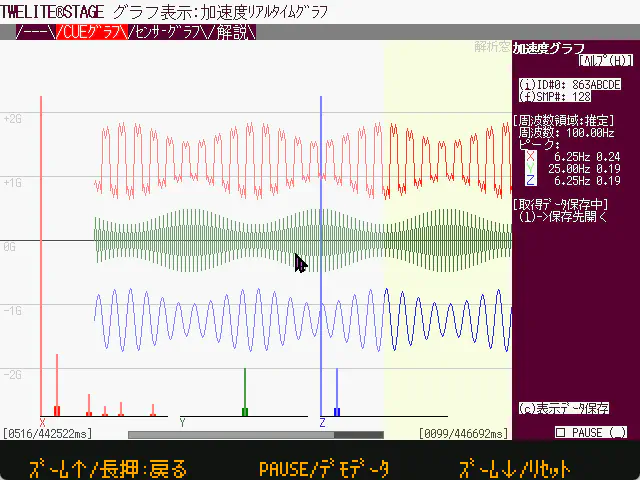
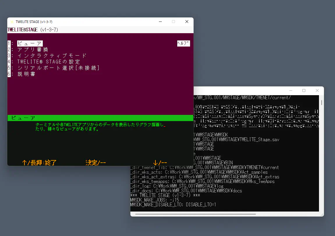
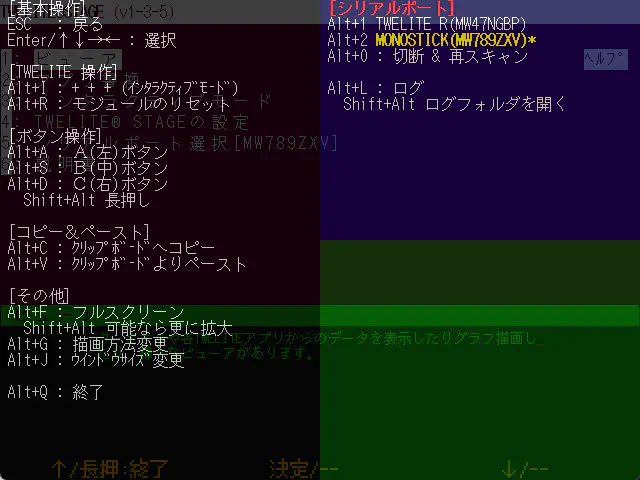
![Example of virtual [ B ] button displayed at the bottom of the screen](../../images/stage-app-abc-button.webp)