For suitable output, we recommend to use Google Chrome (15+) or Microsoft Edge (79+).
As of 2026-04-20 Acquire and Control Data from the Extremely Simple! Standard App Explanation of the sample sketch monitor_spot_app_twelite that retrieves and displays data from the Extremely Simple! Standard App
This is an explanation of the sample sketch
monitor_spot_app_twelite that retrieves and displays data from the Extremely Simple! Standard App (App_Twelite). At the end, we will make a modification to operate the output port of the remote device.
1 - Acquire and Control Data from the Extremely Simple! Standard App Latest
This is an explanation of the sample sketch
monitor_spot_app_twelite that acquires and displays data from the Extremely Simple! Standard App (App_Twelite). At the end, we will make modifications to operate the output port of the remote device.
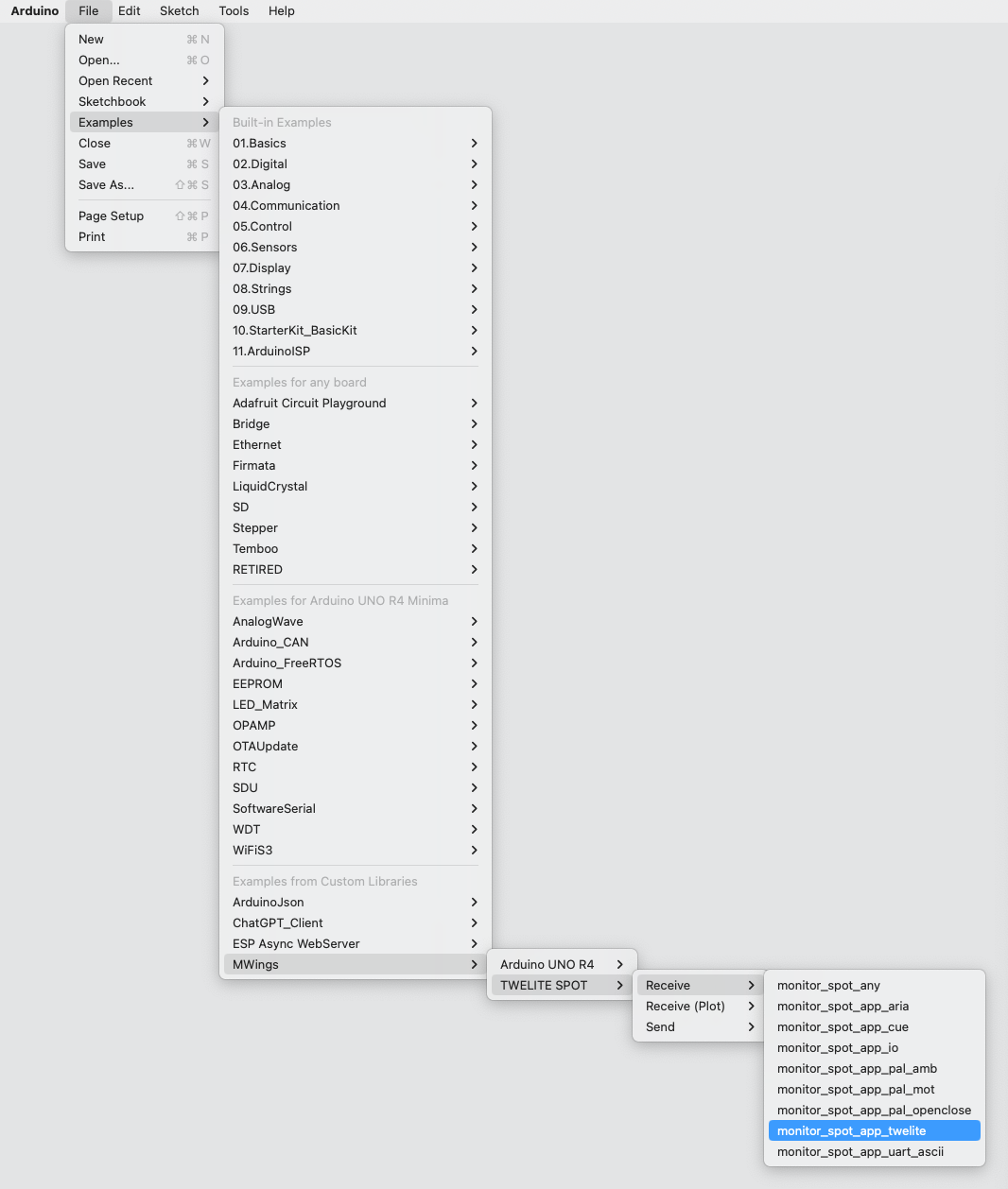
Location of the Sample Sketch If you have installed the MWings library , you can open the sketch from Arduino IDE’s File -> Examples -> MWings -> TWELITE SPOT -> Receive -> monitor_spot_app_twelite.
Example of the location display
Sketch Below is the main source code.
// Monitor example for TWELITE SPOT: Receive data from App_Twelite
#include <Arduino.h>
#include "MWings.h"
const int RST_PIN = 5 ;
const int PRG_PIN = 4 ;
const int LED_PIN = 18 ;
const int8_t RX1_PIN = 16 ;
const int8_t TX1_PIN = 17 ;
const uint8_t TWE_CHANNEL = 18 ;
const uint32_t TWE_APP_ID = 0x67720102 ;
void setup ()
{
// Initialize serial ports
115200 );
Serial.println("Monitor example for TWELITE SPOT: App_Twelite" );
Serial2.begin(115200 , SERIAL_8N1, RX1_PIN, TX1_PIN);
// Initialize TWELITE
LED_PIN, RST_PIN, PRG_PIN,
TWE_CHANNEL, TWE_APP_ID);
// Attach an event handler to process packets from App_Twelite
const ParsedAppTwelitePacket& packet) {
Serial.println("" );
Serial.print("Packet Timestamp: " );
Serial.print(packet.u16SequenceNumber / 64.0f , 1 ); Serial.println(" sec" );
Serial.print("Source Logical ID: 0x" );
Serial.println(packet.u8SourceLogicalId, HEX);
Serial.print("LQI: " );
Serial.println(packet.u8Lqi, DEC);
Serial.print("Supply Voltage: " );
Serial.print(packet.u16SupplyVoltage, DEC); Serial.println(" mV" );
Serial.print("Digital Input: " );
Serial.print(packet.bDiState[0 ] ? " DI1:Lo" : " DI1:Hi" );
Serial.print(packet.bDiState[1 ] ? " DI2:Lo" : " DI2:Hi" );
Serial.print(packet.bDiState[2 ] ? " DI3:Lo" : " DI3:Hi" );
Serial.println(packet.bDiState[3 ] ? " DI4:Lo" : " DI4:Hi" );
Serial.print("Analog Input: " );
Serial.print(" AI1:" ); Serial.print(packet.u16AiVoltage[0 ]); Serial.print(" mV" );
Serial.print(" AI2:" ); Serial.print(packet.u16AiVoltage[1 ]); Serial.print(" mV" );
Serial.print(" AI3:" ); Serial.print(packet.u16AiVoltage[2 ]); Serial.print(" mV" );
Serial.print(" AI4:" ); Serial.print(packet.u16AiVoltage[3 ]); Serial.println(" mV" );
});
}
void loop ()
{
// Update TWELITE
} Including the Library Line 4 includes the MWings library .
Pin Number Definitions Lines 6-11 define the pin numbers.
const int RST_PIN = 5 ;
const int PRG_PIN = 4 ;
const int LED_PIN = 18 ;
const int8_t RX1_PIN = 16 ;
const int8_t TX1_PIN = 17 ; Name Description RST_PINPin number connected to the RST pin of TWELITE PRG_PINPin number connected to the PRG pin of TWELITE LED_PINPin number connected to the ESP32 onboard LED RX1_PINPin number connected to the RX1 pin of TWELITE TX1_PINPin number connected to the TX1 pin of TWELITE
TWELITE Configuration Definitions Lines 13-14 define the settings applied to the TWELITE parent device mounted on the TWELITE SPOT.
const uint8_t TWE_CHANNEL = 18 ;
const uint32_t TWE_APP_ID = 0x67720102 ; Name Description TWE_CHANNELFrequency channel of TWELITE TWE_APP_IDApplication ID of TWELITE
The values in the sketch are the initial values of the Extremely Simple! Standard App.
Serial Port Setup Lines 19-21 initialize the serial ports used and output a startup message to the serial monitor.
Serial.begin(115200 );
Serial.println("Monitor example for TWELITE SPOT: App_Twelite" );
Serial2.begin(115200 , SERIAL_8N1, RX1_PIN, TX1_PIN); Serial is used for communication with the Arduino IDE serial monitor. The baud rate is set to 115200 bps to match the serial monitor settings.
On the other hand, Serial2 is used for communication with the TWELITE parent device mounted on the TWELITE SPOT. The baud rate is also set to 115200 bps to match the initial setting of the TWELITE parent device.
TWELITE Configuration Lines 24-27 call Twelite.begin()
    Twelite.begin(Serial2,
                      LED_PIN, RST_PIN, PRG_PIN,
                      TWE_CHANNEL, TWE_APP_ID);
Registering Packet Reception Event Lines 29-49 call Twelite.on()
Here, the contents of the received packet are output to the serial monitor.
Twelite.on([](const ParsedAppTwelitePacket& packet) {
Serial.println("" );
Serial.print("Packet Timestamp: " );
Serial.print(packet.u16SequenceNumber / 64.0f , 1 ); Serial.println(" sec" );
Serial.print("Source Logical ID: 0x" );
Serial.println(packet.u8SourceLogicalId, HEX);
Serial.print("LQI: " );
Serial.println(packet.u8Lqi, DEC);
Serial.print("Supply Voltage: " );
Serial.print(packet.u16SupplyVoltage, DEC); Serial.println(" mV" );
Serial.print("Digital Input: " );
Serial.print(packet.bDiState[0 ] ? " DI1:Lo" : " DI1:Hi" );
Serial.print(packet.bDiState[1 ] ? " DI2:Lo" : " DI2:Hi" );
Serial.print(packet.bDiState[2 ] ? " DI3:Lo" : " DI3:Hi" );
Serial.println(packet.bDiState[3 ] ? " DI4:Lo" : " DI4:Hi" );
Serial.print("Analog Input: " );
Serial.print(" AI1:" ); Serial.print(packet.u16AiVoltage[0 ]); Serial.print(" mV" );
Serial.print(" AI2:" ); Serial.print(packet.u16AiVoltage[1 ]); Serial.print(" mV" );
Serial.print(" AI3:" ); Serial.print(packet.u16AiVoltage[2 ]); Serial.print(" mV" );
Serial.print(" AI4:" ); Serial.print(packet.u16AiVoltage[3 ]); Serial.println(" mV" );
}); The above event is called only when a packet is received from the Extremely Simple! Standard App.
The contents of the received packet are stored in the argument packet of type ParsedAppTwelitePacket
Message Contents Message Description Packet TimestampPacket timestamp Source Logical IDLogical device ID of the sending TWELITE LQIWireless communication quality (0–255) Supply VoltagePower supply voltage (mV) Digital InputDigital input state Analog InputAnalog input state
Updating TWELITE Data Line 55 calls Twelite.update()
Operating the Remote Output Port Let’s not only acquire the input port state of the Extremely Simple! Standard App but also operate its output port.
Here, based on the LQI (wireless communication quality) when the TWELITE SPOT receives data, we will try to light up the digital output port of the remote device when it approaches the TWELITE SPOT.
Sketch Modification Modification Details First, add the following code at line 16.
AppTweliteCommand command; The above code creates an AppTweliteCommand
Next, add the following code at lines 52-54.
command.u8DestinationLogicalId = packet.u8SourceLogicalId; // LID
0 ] = (packet.u8Lqi >= 100 ) ? true : false; // DI1
The above code manipulates the AppTweliteCommandTwelite.send()
Here, the logical device ID of the destination is set, and the state of the output port (DO1) is specified.
For details, please refer to the AppTweliteCommand reference
This completes the sketch modification. Below is the modified code.
// Monitor example for TWELITE SPOT: Receive data from and send data to App_Twelite
#include <Arduino.h>
#include "MWings.h"
const int RST_PIN = 5 ;
const int PRG_PIN = 4 ;
const int LED_PIN = 18 ;
const int8_t RX1_PIN = 16 ;
const int8_t TX1_PIN = 17 ;
const uint8_t TWE_CHANNEL = 18 ;
const uint32_t TWE_APP_ID = 0x67720102 ;
AppTweliteCommand command;
void setup ()
{
// Initialize serial ports
115200 );
Serial.println("Monitor example for TWELITE SPOT: App_Twelite" );
Serial2.begin(115200 , SERIAL_8N1, RX1_PIN, TX1_PIN);
// Initialize TWELITE
LED_PIN, RST_PIN, PRG_PIN,
TWE_CHANNEL, TWE_APP_ID);
// Attach an event handler to process packets from App_Twelite
const ParsedAppTwelitePacket& packet) {
Serial.println("" );
Serial.print("Packet Timestamp: " );
Serial.print(packet.u16SequenceNumber / 64.0f , 1 ); Serial.println(" sec" );
Serial.print("Source Logical ID: 0x" );
Serial.println(packet.u8SourceLogicalId, HEX);
Serial.print("LQI: " );
Serial.println(packet.u8Lqi, DEC);
Serial.print("Supply Voltage: " );
Serial.print(packet.u16SupplyVoltage, DEC); Serial.println(" mV" );
Serial.print("Digital Input: " );
Serial.print(packet.bDiState[0 ] ? " DI1:Lo" : " DI1:Hi" );
Serial.print(packet.bDiState[1 ] ? " DI2:Lo" : " DI2:Hi" );
Serial.print(packet.bDiState[2 ] ? " DI3:Lo" : " DI3:Hi" );
Serial.println(packet.bDiState[3 ] ? " DI4:Lo" : " DI4:Hi" );
Serial.print("Analog Input: " );
Serial.print(" AI1:" ); Serial.print(packet.u16AiVoltage[0 ]); Serial.print(" mV" );
Serial.print(" AI2:" ); Serial.print(packet.u16AiVoltage[1 ]); Serial.print(" mV" );
Serial.print(" AI3:" ); Serial.print(packet.u16AiVoltage[2 ]); Serial.print(" mV" );
Serial.print(" AI4:" ); Serial.print(packet.u16AiVoltage[3 ]); Serial.println(" mV" );
command.u8DestinationLogicalId = packet.u8SourceLogicalId; // LID
0 ] = (packet.u8Lqi >= 100 ) ? true : false; // DI1
});
}
void loop ()
{
// Update TWELITE
} Operation Check Connect an LED and a current limiting resistor between the DO1 pin and VCC pin of the TWELITE DIP child device.
When you upload the modified sketch, the LED lights up when the TWELITE DIP approaches the TWELITE SPOT (i.e., when communication quality is good).
You were able to control the child device from the TWELITE SPOT!
2 - Acquire and Control Data from the Extremely Simple! Standard App v1.0.1
This is an explanation of the sample sketch
monitor_spot_app_twelite that acquires and displays data from the Extremely Simple! Standard App (App_Twelite). At the end, we will modify it to control the output port of the remote device.
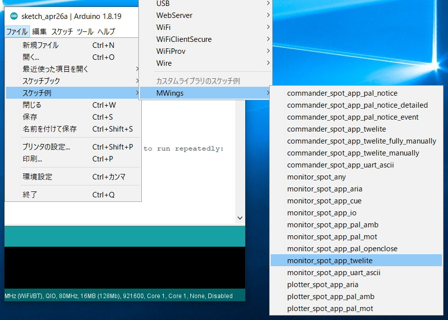
Location of the Sample Sketch If you have installed the MWings library , you can open the sketch in Arduino IDE from File -> Examples -> MWings -> monitor_spot_app_twelite.
Location
Sketch Below is the main source code.
// Monitor example for TWELITE SPOT: Receive data from App_Twelite
#include <Arduino.h>
#include "MWings.h"
const int RST_PIN = 5 ;
const int PRG_PIN = 4 ;
const int LED_PIN = 18 ;
const uint8_t TWE_CHANNEL = 18 ;
const uint32_t TWE_APP_ID = 0x67720102 ;
void setup ()
{
// Initialize serial ports
115200 );
Serial.println("Monitor example for TWELITE SPOT: App_Twelite" );
Serial2.begin(115200 , SERIAL_8N1);
// Initialize TWELITE
LED_PIN, RST_PIN, PRG_PIN,
TWE_CHANNEL, TWE_APP_ID);
// Attach an event handler to process packets from App_Twelite
const ParsedAppTwelitePacket& packet) {
Serial.println("" );
Serial.print("Packet Timestamp: " );
Serial.print(packet.u16SequenceNumber / 64.0f , 1 ); Serial.println(" sec" );
Serial.print("Source Logical ID: 0x" );
Serial.println(packet.u8SourceLogicalId, HEX);
Serial.print("LQI: " );
Serial.println(packet.u8Lqi, DEC);
Serial.print("Supply Voltage: " );
Serial.print(packet.u16SupplyVoltage, DEC); Serial.println(" mV" );
Serial.print("Digital Input: " );
Serial.print(packet.bDiState[0 ] ? " DI1:Lo" : " DI1:Hi" );
Serial.print(packet.bDiState[1 ] ? " DI2:Lo" : " DI2:Hi" );
Serial.print(packet.bDiState[2 ] ? " DI3:Lo" : " DI3:Hi" );
Serial.println(packet.bDiState[3 ] ? " DI4:Lo" : " DI4:Hi" );
Serial.print("Analog Input: " );
Serial.print(" AI1:" ); Serial.print(packet.u16AiVoltage[0 ]); Serial.print(" mV" );
Serial.print(" AI2:" ); Serial.print(packet.u16AiVoltage[1 ]); Serial.print(" mV" );
Serial.print(" AI3:" ); Serial.print(packet.u16AiVoltage[2 ]); Serial.print(" mV" );
Serial.print(" AI4:" ); Serial.print(packet.u16AiVoltage[3 ]); Serial.println(" mV" );
});
}
void loop ()
{
// Update TWELITE
} Including the Library Line 4 includes the MWings library .
Defining Pin Numbers Lines 6-8 define the pin numbers.
const int RST_PIN = 5 ;
const int PRG_PIN = 4 ;
const int LED_PIN = 18 ; Name Description RST_PINPin number connected to the RST pin of TWELITE PRG_PINPin number connected to the PRG pin of TWELITE LED_PINPin number connected to the ESP32 onboard LED
Defining TWELITE Settings Lines 10-11 define the settings applied to the TWELITE parent device mounted on the TWELITE SPOT.
const uint8_t TWE_CHANNEL = 18 ;
const uint32_t TWE_APP_ID = 0x67720102 ; Name Description TWE_CHANNELTWELITE frequency channel TWE_APP_IDTWELITE application ID
The values in the sketch are the default values for the Extremely Simple! Standard App.
Serial Port Settings Lines 16-18 initialize the serial ports used and output a startup message to the serial monitor.
Serial.begin(115200 );
Serial.println("Monitor example for TWELITE SPOT: App_Twelite" );
Serial2.begin(115200 , SERIAL_8N1); Serial is used for communication with the Arduino IDE’s serial monitor. The baud rate is set to 115200 bps to match the serial monitor settings.
On the other hand, Serial2 is used for communication with the TWELITE parent device mounted on the TWELITE SPOT. The baud rate is also set to 115200 bps to match the initial settings of the TWELITE parent device.
TWELITE Configuration Lines 21-23 call Twelite.begin()
    Twelite.begin(Serial2,
                      LED_PIN, RST_PIN, PRG_PIN,
                      TWE_CHANNEL, TWE_APP_ID);
Registering Packet Reception Event Lines 26-46 call Twelite.on()
Here, the contents of the received packet are output to the serial monitor.
Twelite.on([](const ParsedAppTwelitePacket& packet) {
Serial.println("" );
Serial.print("Packet Timestamp: " );
Serial.print(packet.u16SequenceNumber / 64.0f , 1 ); Serial.println(" sec" );
Serial.print("Source Logical ID: 0x" );
Serial.println(packet.u8SourceLogicalId, HEX);
Serial.print("LQI: " );
Serial.println(packet.u8Lqi, DEC);
Serial.print("Supply Voltage: " );
Serial.print(packet.u16SupplyVoltage, DEC); Serial.println(" mV" );
Serial.print("Digital Input: " );
Serial.print(packet.bDiState[0 ] ? " DI1:Lo" : " DI1:Hi" );
Serial.print(packet.bDiState[1 ] ? " DI2:Lo" : " DI2:Hi" );
Serial.print(packet.bDiState[2 ] ? " DI3:Lo" : " DI3:Hi" );
Serial.println(packet.bDiState[3 ] ? " DI4:Lo" : " DI4:Hi" );
Serial.print("Analog Input: " );
Serial.print(" AI1:" ); Serial.print(packet.u16AiVoltage[0 ]); Serial.print(" mV" );
Serial.print(" AI2:" ); Serial.print(packet.u16AiVoltage[1 ]); Serial.print(" mV" );
Serial.print(" AI3:" ); Serial.print(packet.u16AiVoltage[2 ]); Serial.print(" mV" );
Serial.print(" AI4:" ); Serial.print(packet.u16AiVoltage[3 ]); Serial.println(" mV" );
}); The above event is called only when a packet is received from the Extremely Simple! Standard App.
The contents of the received packet are stored in the argument packet of type ParsedAppTwelitePacket
Message Contents Message Description Packet TimestampPacket timestamp Source Logical IDLogical device ID of the sending TWELITE LQIWireless communication quality (0–255) Supply VoltagePower supply voltage (mV) Digital InputDigital input state Analog InputAnalog input state
Updating TWELITE Data Line 52 calls Twelite.update()
Controlling the Output Port of the Remote Device Not only can you acquire the input port state of the Extremely Simple! Standard App, but you can also control the output port of the Extremely Simple! Standard App.
Here, based on the LQI (wireless communication quality) received by the TWELITE SPOT, when the remote device approaches the TWELITE SPOT, the digital output port of the remote device is turned on.
Modifying the Sketch Modification Details First, add the following code at line 13.
AppTweliteCommand command; The above code creates an AppTweliteCommand
Next, add the following code at lines 49-51.
command.u8DestinationLogicalId = packet.u8SourceLogicalId; // LID
0 ] = (packet.u8Lqi >= 100 ) ? true : false; // DI1
The above code manipulates AppTweliteCommandTwelite.send()
Here, the logical device ID of the destination is set, and the output port (DO1) state is specified.
For more details, please see the AppTweliteCommand reference
This completes the modification of the sketch. The modified code is shown below.
// Monitor example for TWELITE SPOT: Receive data from and send data to App_Twelite
#include <Arduino.h>
#include "MWings.h"
const int RST_PIN = 5 ;
const int PRG_PIN = 4 ;
const int LED_PIN = 18 ;
const uint8_t TWE_CHANNEL = 18 ;
const uint32_t TWE_APP_ID = 0x67720102 ;
AppTweliteCommand command;
void setup ()
{
// Initialize serial ports
115200 );
Serial.println("Monitor example for TWELITE SPOT: App_Twelite" );
Serial2.begin(115200 , SERIAL_8N1);
// Initialize TWELITE
LED_PIN, RST_PIN, PRG_PIN,
TWE_CHANNEL, TWE_APP_ID);
// Attach an event handler to process packets from App_Twelite
const ParsedAppTwelitePacket& packet) {
Serial.println("" );
Serial.print("Packet Timestamp: " );
Serial.print(packet.u16SequenceNumber / 64.0f , 1 ); Serial.println(" sec" );
Serial.print("Source Logical ID: 0x" );
Serial.println(packet.u8SourceLogicalId, HEX);
Serial.print("LQI: " );
Serial.println(packet.u8Lqi, DEC);
Serial.print("Supply Voltage: " );
Serial.print(packet.u16SupplyVoltage, DEC); Serial.println(" mV" );
Serial.print("Digital Input: " );
Serial.print(packet.bDiState[0 ] ? " DI1:Lo" : " DI1:Hi" );
Serial.print(packet.bDiState[1 ] ? " DI2:Lo" : " DI2:Hi" );
Serial.print(packet.bDiState[2 ] ? " DI3:Lo" : " DI3:Hi" );
Serial.println(packet.bDiState[3 ] ? " DI4:Lo" : " DI4:Hi" );
Serial.print("Analog Input: " );
Serial.print(" AI1:" ); Serial.print(packet.u16AiVoltage[0 ]); Serial.print(" mV" );
Serial.print(" AI2:" ); Serial.print(packet.u16AiVoltage[1 ]); Serial.print(" mV" );
Serial.print(" AI3:" ); Serial.print(packet.u16AiVoltage[2 ]); Serial.print(" mV" );
Serial.print(" AI4:" ); Serial.print(packet.u16AiVoltage[3 ]); Serial.println(" mV" );
command.u8DestinationLogicalId = packet.u8SourceLogicalId; // LID
0 ] = (packet.u8Lqi >= 100 ) ? true : false; // DI1
});
}
void loop ()
{
// Update TWELITE
} Operation Confirmation Connect an LED and a current limiting resistor between the DO1 pin and the VCC pin of the child TWELITE DIP.
When you upload the modified sketch, the LED on the TWELITE DIP lights up when it approaches the TWELITE SPOT (i.e., when the communication quality is good).
You have successfully controlled the child device from the TWELITE SPOT!
3 - Acquire and Control Data from the Extremely Simple! Standard App v1.3.1
This is an explanation of the sample sketch
monitor_spot_app_twelite that acquires and displays data from the Extremely Simple! Standard App (App_Twelite). At the end, we will make a modification to control the output ports of the remote device.
Location of the Sample Sketch If you have installed the MWings library , you can open the sketch from Arduino IDE by File -> Examples -> MWings -> TWELITE SPOT -> Receive -> monitor_spot_app_twelite.
Example of the location display
Sketch Below is the main source code.
// Monitor example for TWELITE SPOT: Receive data from App_Twelite
#include <Arduino.h>
#include "MWings.h"
const int RST_PIN = 5 ;
const int PRG_PIN = 4 ;
const int LED_PIN = 18 ;
const uint8_t TWE_CHANNEL = 18 ;
const uint32_t TWE_APP_ID = 0x67720102 ;
void setup ()
{
// Initialize serial ports
115200 );
Serial.println("Monitor example for TWELITE SPOT: App_Twelite" );
Serial2.begin(115200 , SERIAL_8N1);
// Initialize TWELITE
LED_PIN, RST_PIN, PRG_PIN,
TWE_CHANNEL, TWE_APP_ID);
// Attach an event handler to process packets from App_Twelite
const ParsedAppTwelitePacket& packet) {
Serial.println("" );
Serial.print("Packet Timestamp: " );
Serial.print(packet.u16SequenceNumber / 64.0f , 1 ); Serial.println(" sec" );
Serial.print("Source Logical ID: 0x" );
Serial.println(packet.u8SourceLogicalId, HEX);
Serial.print("LQI: " );
Serial.println(packet.u8Lqi, DEC);
Serial.print("Supply Voltage: " );
Serial.print(packet.u16SupplyVoltage, DEC); Serial.println(" mV" );
Serial.print("Digital Input: " );
Serial.print(packet.bDiState[0 ] ? " DI1:Lo" : " DI1:Hi" );
Serial.print(packet.bDiState[1 ] ? " DI2:Lo" : " DI2:Hi" );
Serial.print(packet.bDiState[2 ] ? " DI3:Lo" : " DI3:Hi" );
Serial.println(packet.bDiState[3 ] ? " DI4:Lo" : " DI4:Hi" );
Serial.print("Analog Input: " );
Serial.print(" AI1:" ); Serial.print(packet.u16AiVoltage[0 ]); Serial.print(" mV" );
Serial.print(" AI2:" ); Serial.print(packet.u16AiVoltage[1 ]); Serial.print(" mV" );
Serial.print(" AI3:" ); Serial.print(packet.u16AiVoltage[2 ]); Serial.print(" mV" );
Serial.print(" AI4:" ); Serial.print(packet.u16AiVoltage[3 ]); Serial.println(" mV" );
});
}
void loop ()
{
// Update TWELITE
} Including the Library Line 4 includes the MWings library .
Defining Pin Numbers Lines 6-8 define the pin numbers.
const int RST_PIN = 5 ;
const int PRG_PIN = 4 ;
const int LED_PIN = 18 ; Name Description RST_PINPin number connected to the RST pin of TWELITE PRG_PINPin number connected to the PRG pin of TWELITE LED_PINPin number connected to the ESP32 onboard LED
Defining TWELITE Settings Lines 10-11 define the settings applied to the TWELITE master device mounted on TWELITE SPOT.
const uint8_t TWE_CHANNEL = 18 ;
const uint32_t TWE_APP_ID = 0x67720102 ; Name Description TWE_CHANNELTWELITE frequency channel TWE_APP_IDTWELITE application ID
The values in this sketch are the default values for the Extremely Simple! Standard App.
Setting up Serial Ports Lines 16-18 initialize the serial ports used and output a startup message to the serial monitor.
Serial.begin(115200 );
Serial.println("Monitor example for TWELITE SPOT: App_Twelite" );
Serial2.begin(115200 , SERIAL_8N1); Serial is used for communication with the Arduino IDE serial monitor. The baud rate is set to 115200 bps to match the serial monitor settings.
On the other hand, Serial2 is used for communication with the TWELITE master device mounted on TWELITE SPOT. The baud rate is also set to 115200 bps to match the TWELITE master device’s initial settings.
Configuring TWELITE Lines 21-23 call Twelite.begin()
    Twelite.begin(Serial2,
                      LED_PIN, RST_PIN, PRG_PIN,
                      TWE_CHANNEL, TWE_APP_ID);
Registering Event for Packet Reception Lines 26-46 call Twelite.on()
Here, the received packet contents are output to the serial monitor.
Twelite.on([](const ParsedAppTwelitePacket& packet) {
Serial.println("" );
Serial.print("Packet Timestamp: " );
Serial.print(packet.u16SequenceNumber / 64.0f , 1 ); Serial.println(" sec" );
Serial.print("Source Logical ID: 0x" );
Serial.println(packet.u8SourceLogicalId, HEX);
Serial.print("LQI: " );
Serial.println(packet.u8Lqi, DEC);
Serial.print("Supply Voltage: " );
Serial.print(packet.u16SupplyVoltage, DEC); Serial.println(" mV" );
Serial.print("Digital Input: " );
Serial.print(packet.bDiState[0 ] ? " DI1:Lo" : " DI1:Hi" );
Serial.print(packet.bDiState[1 ] ? " DI2:Lo" : " DI2:Hi" );
Serial.print(packet.bDiState[2 ] ? " DI3:Lo" : " DI3:Hi" );
Serial.println(packet.bDiState[3 ] ? " DI4:Lo" : " DI4:Hi" );
Serial.print("Analog Input: " );
Serial.print(" AI1:" ); Serial.print(packet.u16AiVoltage[0 ]); Serial.print(" mV" );
Serial.print(" AI2:" ); Serial.print(packet.u16AiVoltage[1 ]); Serial.print(" mV" );
Serial.print(" AI3:" ); Serial.print(packet.u16AiVoltage[2 ]); Serial.print(" mV" );
Serial.print(" AI4:" ); Serial.print(packet.u16AiVoltage[3 ]); Serial.println(" mV" );
}); The above event is called only when a packet is received from the Extremely Simple! Standard App.
The received packet contents are stored in the argument packet of type ParsedAppTwelitePacket
Contents of Messages Message Description Packet TimestampPacket timestamp Source Logical IDLogical device ID of the sending TWELITE LQIWireless communication quality (0-255) Supply VoltageSupply voltage (mV) Digital InputDigital input state Analog InputAnalog input state
Updating TWELITE Data Line 52 calls Twelite.update()
Controlling the Remote Output Ports Let’s not only acquire the state of the input ports of the Extremely Simple! Standard App, but also try controlling its output ports.
Here, based on the LQI (wireless communication quality) when the TWELITE SPOT receives data, we will light up the digital output port of the remote device when it approaches the TWELITE SPOT.
Modifying the Sketch Modifications First, add the following code at line 13.
AppTweliteCommand command; The above code creates an AppTweliteCommand
Next, add the following code at lines 49-51.
command.u8DestinationLogicalId = packet.u8SourceLogicalId; // LID
0 ] = (packet.u8Lqi >= 100 ) ? true : false; // DI1
The above code manipulates AppTweliteCommandTwelite.send()
Here, the destination logical device ID is set, and the output port (DO1) state is specified.
For details, see the AppTweliteCommand reference
This completes the modification of the sketch. The modified code is shown below.
// Monitor example for TWELITE SPOT: Receive data from and send data to App_Twelite
#include <Arduino.h>
#include "MWings.h"
const int RST_PIN = 5 ;
const int PRG_PIN = 4 ;
const int LED_PIN = 18 ;
const uint8_t TWE_CHANNEL = 18 ;
const uint32_t TWE_APP_ID = 0x67720102 ;
AppTweliteCommand command;
void setup ()
{
// Initialize serial ports
115200 );
Serial.println("Monitor example for TWELITE SPOT: App_Twelite" );
Serial2.begin(115200 , SERIAL_8N1);
// Initialize TWELITE
LED_PIN, RST_PIN, PRG_PIN,
TWE_CHANNEL, TWE_APP_ID);
// Attach an event handler to process packets from App_Twelite
const ParsedAppTwelitePacket& packet) {
Serial.println("" );
Serial.print("Packet Timestamp: " );
Serial.print(packet.u16SequenceNumber / 64.0f , 1 ); Serial.println(" sec" );
Serial.print("Source Logical ID: 0x" );
Serial.println(packet.u8SourceLogicalId, HEX);
Serial.print("LQI: " );
Serial.println(packet.u8Lqi, DEC);
Serial.print("Supply Voltage: " );
Serial.print(packet.u16SupplyVoltage, DEC); Serial.println(" mV" );
Serial.print("Digital Input: " );
Serial.print(packet.bDiState[0 ] ? " DI1:Lo" : " DI1:Hi" );
Serial.print(packet.bDiState[1 ] ? " DI2:Lo" : " DI2:Hi" );
Serial.print(packet.bDiState[2 ] ? " DI3:Lo" : " DI3:Hi" );
Serial.println(packet.bDiState[3 ] ? " DI4:Lo" : " DI4:Hi" );
Serial.print("Analog Input: " );
Serial.print(" AI1:" ); Serial.print(packet.u16AiVoltage[0 ]); Serial.print(" mV" );
Serial.print(" AI2:" ); Serial.print(packet.u16AiVoltage[1 ]); Serial.print(" mV" );
Serial.print(" AI3:" ); Serial.print(packet.u16AiVoltage[2 ]); Serial.print(" mV" );
Serial.print(" AI4:" ); Serial.print(packet.u16AiVoltage[3 ]); Serial.println(" mV" );
command.u8DestinationLogicalId = packet.u8SourceLogicalId; // LID
0 ] = (packet.u8Lqi >= 100 ) ? true : false; // DI1
});
}
void loop ()
{
// Update TWELITE
} Operation Confirmation Connect an LED and a current-limiting resistor between the DO1 pin and the VCC pin of the TWELITE DIP slave device.
When you upload the modified sketch, the LED lights up when the TWELITE DIP approaches the TWELITE SPOT (i.e., when communication quality is good).
You have successfully controlled the slave device from TWELITE SPOT!