This guide explains how to write firmware to the ESP32 and TWELITE embedded in the TWELITE SPOT.
This is the multi-page printable view of this section. Click here to print...
For suitable output, we recommend to use Google Chrome (15+) or Microsoft Edge (79+).
How to Write Firmware
How to write firmware to TWELITE SPOT
- 1: How to Write Firmware to ESP32
- 1.1: How to Write Sketches to ESP32
- 1.2: How to Write Files to ESP32 (Arduino IDE 1.x)
- 1.3: How to Upload Files to ESP32 (Arduino IDE 2.x)
- 1.4: How to Specify the Partition Table for Writing to ESP32
- 2: How to Write Firmware to TWELITE
- 3: How to Initialize Firmware
1 - How to Write Firmware to ESP32
How to write firmware to the ESP32 mounted on TWELITE SPOT
This guide explains how to write firmware to the ESP32 mounted on the TWELITE SPOT.
1.1 - How to Write Sketches to ESP32
How to write sketches to the ESP32 mounted on TWELITE SPOT
This guide explains how to write Arduino sketches to the ESP32 mounted on TWELITE SPOT.
Connecting to the Host
Connect TWELITE R3 / R2
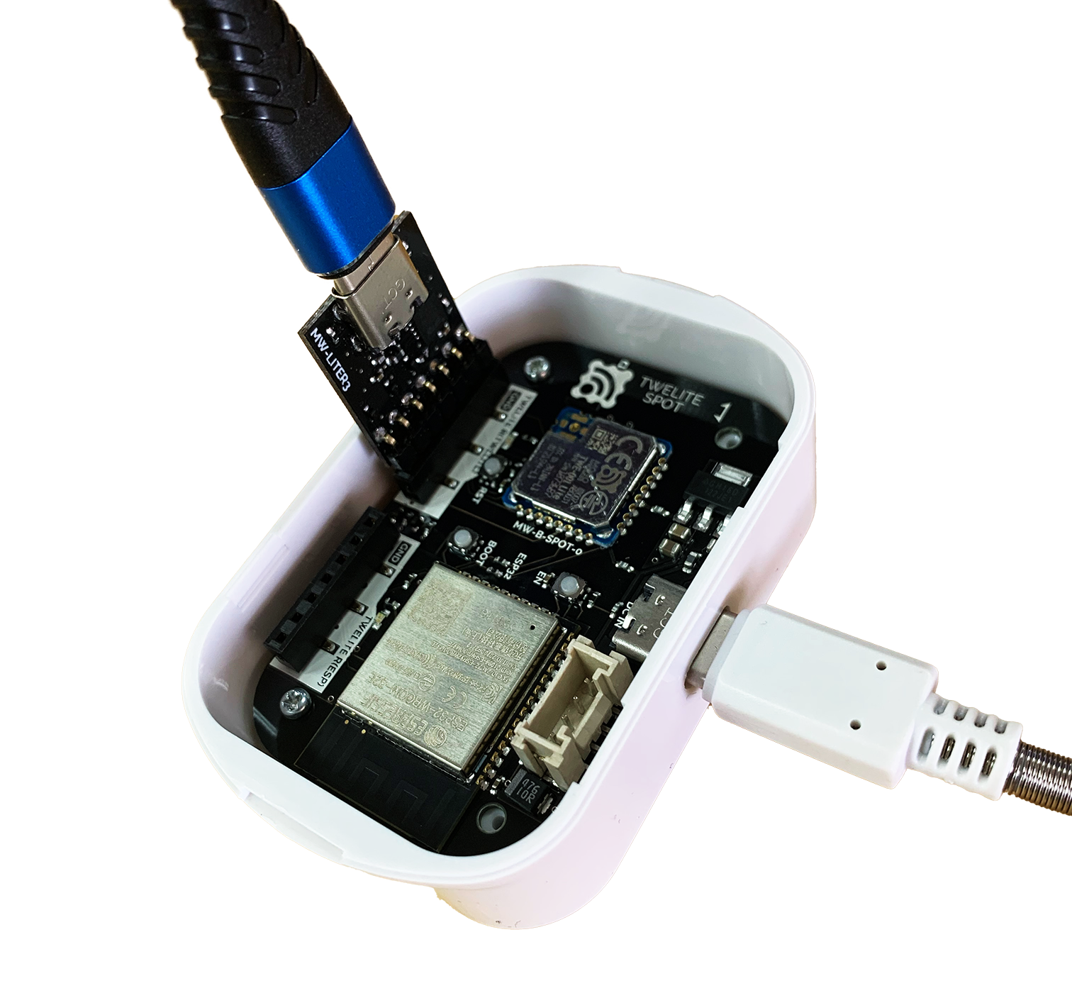
Connect the TWELITE R3 / R2 to the 7P interface (the side labeled ESP32).
Connect Power
Supply 5V power to the USB-C connector on the side.
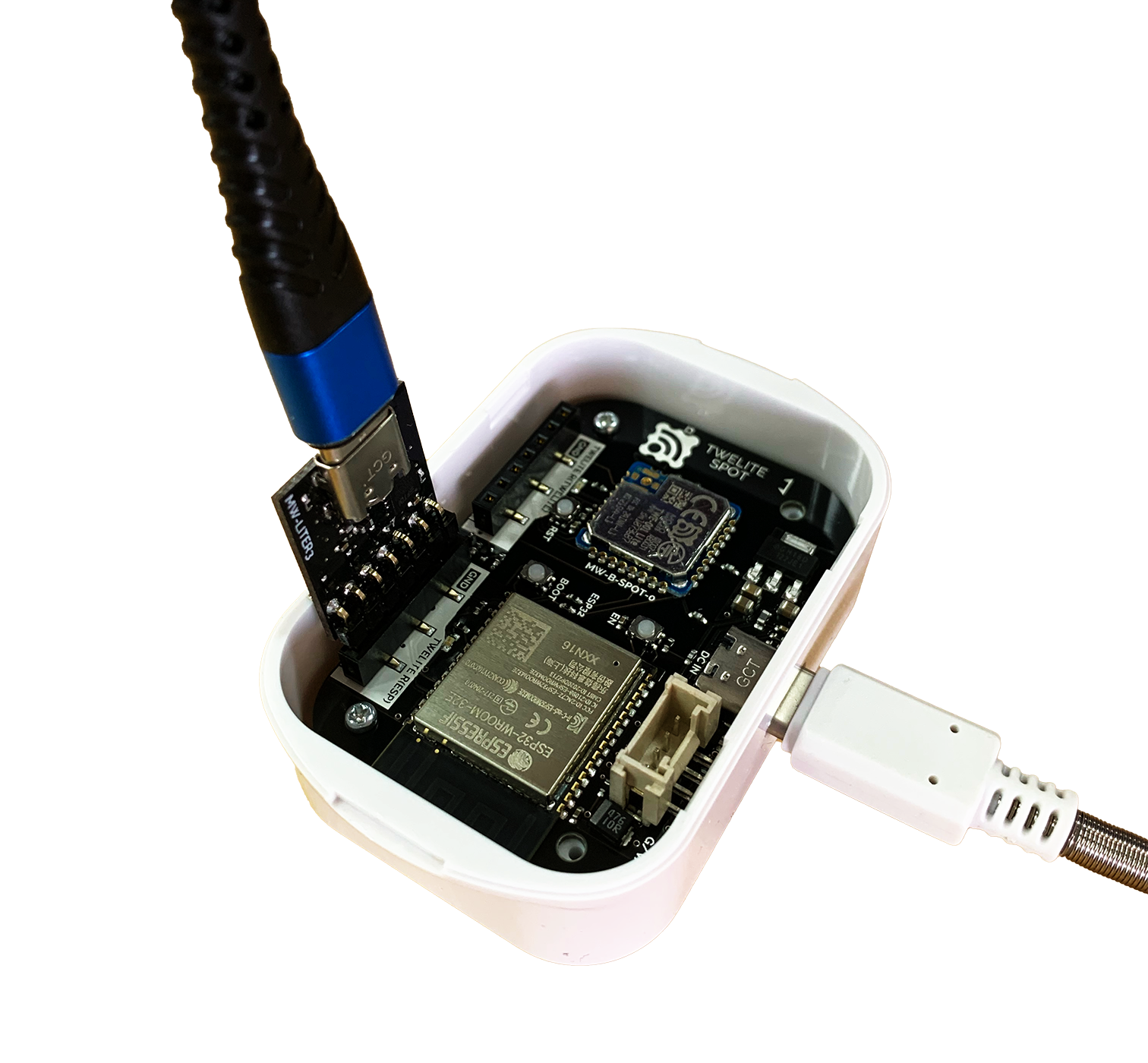
Connection Example (ESP32)
Always connect the TWELITE R3 / R2 to the TWELITE SPOT in the same orientation as shown above. Connecting it incorrectly may damage the TWELITE SPOT or the TWELITE R3 / R2.
Operating Arduino IDE
Open the Sketch
Launch the Arduino IDE and open the sketch you want to write.
Select the Serial Port
From the Tools -> Serial Port menu, select the port for the TWELITE R3 / R2.
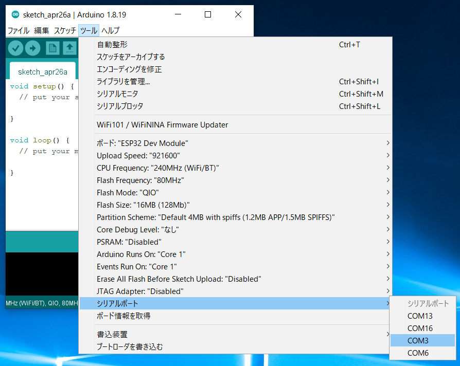
Selecting the Serial Port
On Windows, the serial port name will be like
COM?, and on macOS/Linux, it will be like /dev/tty?.Start ESP32 in Programming Mode
Press the ESP32 reset switch EN(RST) and the ESP32 boot switch BOOT on the TWELITE SPOT, then release them in the order of EN(RST) -> BOOT.
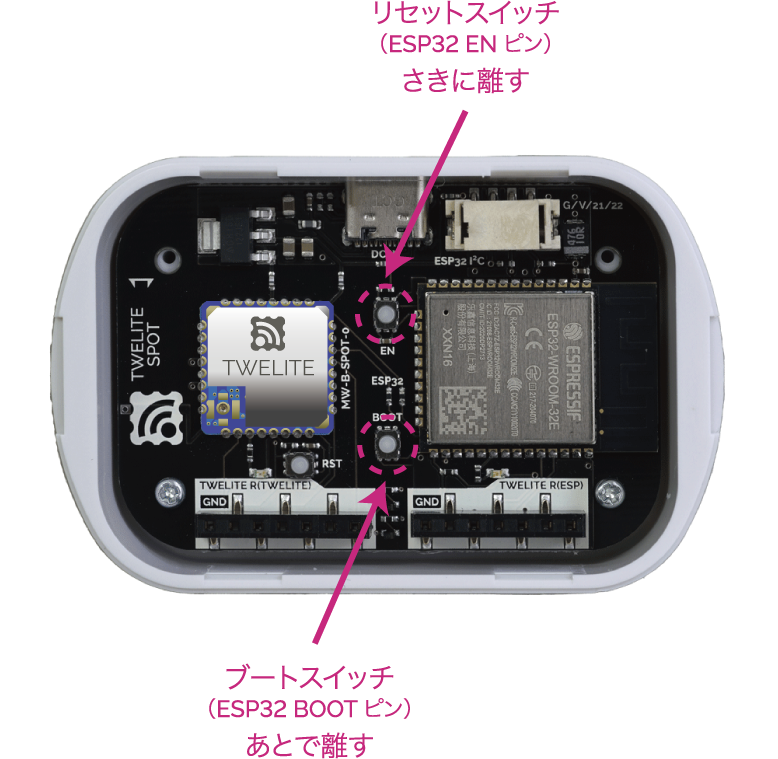
Button Positions
By pressing
BOOT while resetting, you can enter the ESP32 programming mode.Execute Writing
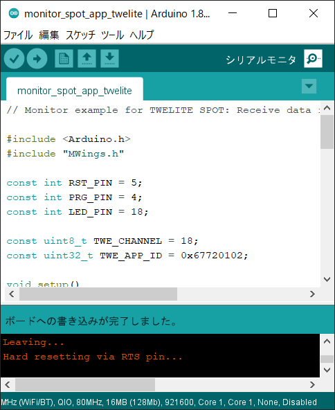
Click the Write to Microcontroller Board button in Arduino IDE.
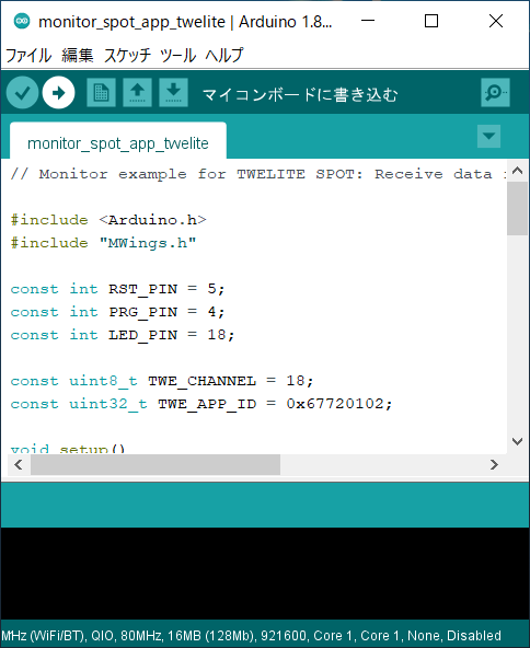
Write to Microcontroller Board
When writing is complete,
Hard resetting via RTS pin... will appear at the bottom of the screen.If writing fails and the following message appears, try changing the USB port or USB cable you are using.
A serial exception error occurred: Could not configure port: (6, 'Device not configured')
Reset ESP32
After writing is complete, press and release the ESP32 reset switch EN(RST) on the TWELITE SPOT to reset the ESP32.
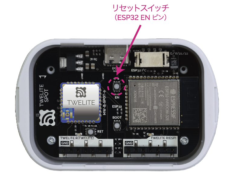
Reset Switch Position
Writing Completion Screen
If you do not reset, you cannot exit programming mode.
1.2 - How to Write Files to ESP32 (Arduino IDE 1.x)
How to write files to the ESP32 mounted on TWELITE SPOT
This guide explains how to write files (the files under the
data/ folder) to the ESP32 mounted on TWELITE SPOT.This article introduces an advanced topic (how to treat the flash area of the ESP32 mounted on TWELITE SPOT as a file system and write files such as HTML).
For example, if you do not need to write HTML files to TWELITE SPOT to behave as a web server (implemented in the spot-server sample) or write encryption key files to TWELITE SPOT, you can ignore the contents of this article.
This article uses third-party open-source software.
We cannot provide detailed instructions on third-party software usage. Also, we assume no responsibility for any damages caused by using third-party software.
The method introduced in this article requires Arduino IDE 1.x. Due to technical constraints, as of May 2023, Arduino IDE 2.x is not supported.
Because the plugin used here is written in Java, it does not work with Arduino IDE 2.x, which is not Java-based unlike Arduino IDE 1.x. For more details, see the Arduino IDE GitHub issue (Missing support for external tools / plugins · Issue #58 · arduino/arduino-ide) (in English).
Installing the Plugin
Install the Arduino plugin (arduino-esp32fs-plugin) to write files to the ESP32 flash area.
Downloading the Plugin
Download esp32fs.zip from the following page:
Release Update to support Big Sur · lorol/arduino-esp32fs-plugin
The original arduino-esp32fs-plugin is me-no-dev/arduino-esp32fs-plugin, but here we use the forked version lorol/arduino-esp32fs-plugin which supports the latest LittleFS file system.
Installing the Plugin
Extract the downloaded
esp32fs.zip.If there is no
toolsfolder in your Arduino sketchbook location (set in Arduino IDE preferences, e.g.,C:\Users\foo\Documents\Arduino), create it.Create the folder
ESP32FS/toolinside thetoolsfolder and place theesp32fs.jarfile extracted from the zip there. (Example path:C:\Users\foo\Documents\Arduino\tools\ESP32FS\tool\esp32fs.jar).The plugin will be available the next time you start Arduino IDE.
Connecting to the Host
Connect TWELITE R3 / R2
Connect TWELITE R3 / R2 to the 7P interface side labeled ESP32.
Connect Power
Supply 5V power to the USB-C connector on the side.
Connection Example (ESP32)
Always connect TWELITE R3 / R2 to TWELITE SPOT in the same orientation as shown above. Connecting in the wrong orientation may damage TWELITE SPOT or TWELITE R3 / R2.
Arduino IDE Operations
Open the Sketch
Start Arduino IDE and open the sketch.
Place Files to Write
Open Sketch -> Show Sketch Folder.
Create a
datafolder at the same level as the sketch file (.ino).Place the files to write inside the
datafolder.
The directory structure inside the
data folder is preserved in the flash area.Select Serial Port
From the Tools -> Port menu, select the port for TWELITE R3 / R2.
Serial Port Selection
On Windows, serial ports are named like
COM?, and on macOS/Linux, like /dev/tty?.Boot ESP32 in Programming Mode
Press the ESP32 reset switch EN(RST) and the ESP32 boot switch BOOT on TWELITE SPOT, then release them in the order EN(RST) -> BOOT.
Button Positions
Resetting while holding
BOOT switches ESP32 into programming mode.Execute Writing
Click Tools -> ESP32 Sketch Data Upload.
At Select FS for
/data folder, select LittleFS.
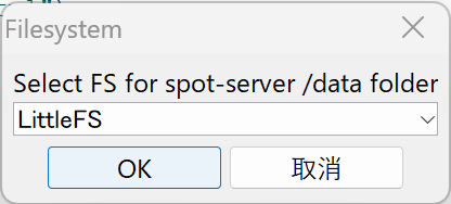
File System Selection Screen
- Click OK.
When writing completes,
Hard resetting via RTS pin... is displayed at the bottom of the screen.Depending on your environment, writing may fail with a message like this (confirmed on macOS):
`Error: esptool not found!`
In that case, placing esptool.py in the Arduino15 folder/packages/esp32/tools/esptool_py/<version>/esptool.py might resolve the issue.
For example, on macOS, obtain esptool.py and create a symbolic link as follows:
/usr/bin/pip3 install esptool
ln -s ~/Library/Python/3.9/bin/esptool.py ~/Library/Arduino15/packages/esp32/tools/esptool_py/4.5.1/esptool.py
Note: Specify
/usr/bin/pip3to avoid installing in the Homebrew directory.
Reset ESP32
After writing completes, press and release the ESP32 reset switch EN(RST) on TWELITE SPOT to reset ESP32.
Reset Switch Position
1.3 - How to Upload Files to ESP32 (Arduino IDE 2.x)
Method for uploading files to the ESP32 mounted on TWELITE SPOT
This guide explains how to upload files (files under the
data/ folder) to the ESP32 mounted on TWELITE SPOT.This section covers advanced topics (how to treat the flash area of the ESP32 mounted on TWELITE SPOT as a file system and upload files like HTML).
If you don’t have requirements such as uploading HTML files to TWELITE SPOT to make it function as a web server (achieved in the spot-server sample) or uploading encryption key files to TWELITE SPOT, you can ignore this section.
This section uses third-party open source software.
We cannot provide detailed usage instructions for third-party software. Also, we assume no responsibility for any damage caused by using third-party software.
The method described in this section uses Arduino IDE 2.x.
Installing the Plugin
Install the Arduino IDE 2.x plugin (earlephilhower/arduino-littlefs-upload) for uploading files to the ESP32 flash area.
Download the Plugin
Download arduino-littlefs-upload-x.x.x.vsix from the following page:
Releases · earlephilhower/arduino-littlefs-upload
Install the Plugin
Place the downloaded arduino-littlefs-upload-x.x.x.vsix in .arduinoIDE/plugins under your user directory.
- Windows example:
C:\Users\foo\.arduinoIDE\plugins\ - macOS/Linux example:
~/.arduinoIDE/plugins/
Host Connection
Connect TWELITE R3 / R2
Connect TWELITE R3 / R2 to the 7P interface (the side marked ESP32).
Connect Power
Supply 5V power to the side USB-C connector.
Connection example (ESP32)
Make sure to connect TWELITE R3 / R2 to TWELITE SPOT in the same orientation as shown in the figure above. Connecting it in the wrong orientation may damage TWELITE SPOT or TWELITE R3 / R2.
Arduino IDE Operations
Open Sketch
Launch Arduino IDE and open your sketch.
Place Files to Upload
Open the sketch folder from Sketch -> Show Sketch Folder.
Create a
datafolder at the same level as the sketch file (.ino).Place the files you want to upload inside the
datafolder.
The hierarchical structure within the
data folder is preserved in the flash area.Select Serial Port
Select the TWELITE R3 / R2 port from Tools -> Port menu.
The serial port will have names like
COM? on Windows, and /dev/tty? on macOS / Linux.Start ESP32 in Program Mode
Press the ESP32 reset switch EN(RST) and ESP32 boot switch BOOT on TWELITE SPOT, then release them in the order EN(RST) -> BOOT.
Button locations
By pressing
BOOT while resetting, you can put the ESP32 into program mode.Execute Upload
Press
Ctrl+Shift+P(or⌘+Shift+Pon macOS) to open the command palette.Select
Upload LittleFS to Pico/ESP8266/ESP32.
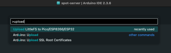
Command palette screen
When the upload is complete,
Completed upload. will be displayed at the bottom of the screen.Reset ESP32
After the upload is complete, press and release the ESP32 reset switch EN(RST) on TWELITE SPOT to reset the ESP32.
Reset switch location
1.4 - How to Specify the Partition Table for Writing to ESP32
How to apply any partition table when writing to the ESP32 mounted on TWELITE SPOT
This guide explains how to apply any partition table when writing sketches or files to the ESP32 mounted on TWELITE SPOT.
This article introduces an advanced topic (how to specify the partition table of the flash area).
If you use the partition table settings included by default in the ESP32 Arduino Core (e.g., Default 4MB with spiffs), you can ignore this article.
We assume no responsibility for any damages caused by applying the settings described in this article.
Creating the Definition File
The partition table is defined in a csv file.
In the example below, out of the 16MB flash area, 8MB is allocated for the file system.
# TWELITE SPOT 16MB with 8MB LittleFS
# Name,  Type, SubType, Offset,   Size,     Flags
nvs,     data, nvs,     0x9000,   0x5000,
otadata, data, ota,     0xE000,   0x2000,
app0,    app,  ota_0,   0x10000,  0x7F0000,
spiffs,  data, spiffs,  0x800000, 0x800000,
TWELITE SPOT 16MB with 8MB LittleFSis the name displayed in the Arduino IDE.nvsis the area used by the system. Do not change.otadatais the area used when using OTA. Do not change.app0is the area where the firmware is written.spiffsis the area used by the LittleFS file system.
The units of the Offset and Size columns in the csv file are bytes, expressed in hexadecimal.
Therefore, the usable sizes for firmware and file system in the above example can be calculated as follows:
- Size of
app0:0x7F0000 = 8323072, approximately7.875MB - Size of
spiffs:0x800000 = 8388608, exactly8MB
Registering the Definition File
Open the Arduino15 folder and add the csv file to the following path:
Arduino15/packages/esp32/hardware/esp32/x.x.x/tools/partitions
x.x.xis the version of Arduino core for the ESP32
Applying the Partition Table
From the Arduino IDE toolbar, open Tools -> Partition Scheme and select the added partition table.
The selected partition table will be applied to subsequent firmware and file system writes.
If a file named
partitions.csv is placed in the same location as the sketch file, that file takes precedence. However, the display in the Arduino IDE does not change, which may cause confusion.2 - How to Write Firmware to TWELITE
How to write firmware to the TWELITE mounted on TWELITE SPOT
This guide explains how to write firmware to the TWELITE mounted on TWELITE SPOT.
The TWELITE SPOT shipped from the factory has the parent/relay application (App_Wings_SPOT) already written to the TWELITE. In the factory default state, there is no need to rewrite the TWELITE firmware.
The TWELITE mounted on TWELITE SPOT does not support configuration changes via interactive mode.
To set the TWELITE frequency channel or application ID, send commands via serial communication from the ESP32. In the Arduino environment, please use Twelite.begin().
Install TWELITE STAGE APP
The following is a simplified explanation for Windows. For macOS/Linux instructions or more detailed information about the TWELITE STAGE APP, please refer to the TWELITE STAGE APP Manual.
Download the TWELITE STAGE SDK and extract the downloaded file directly under the C drive.
Connect to Host
Connect TWELITE R3 / R2
Connect the TWELITE R3 / R2 to the 7P interface (the side labeled TWELITE).
Connect Power
Supply 5V power to the USB-C connector on the side.
Connection Example (TWELITE)
Always connect the TWELITE R3 / R2 to the TWELITE SPOT in the orientation shown above. Connecting it incorrectly may damage the TWELITE SPOT or the TWELITE R3 / R2.
Operating the TWELITE STAGE APP
Launch the TWELITE STAGE APP (
TWELITE_Stage.exe).Select the TWELITE R3 / TWELITE R2 on the serial port selection screen.
From the main menu, select “Rewrite Application” and choose the application you want to rewrite.
For more details, please refer to the TWELITE STAGE APP Manual.
3 - How to Initialize Firmware
How to restore TWELITE SPOT firmware to the factory default state
This guide explains how to initialize the firmware written to the ESP32 and TWELITE installed on the TWELITE SPOT back to the factory default state.
3.1 - How to Initialize ESP32 Firmware
How to restore ESP32 firmware on TWELITE SPOT to the factory default state
This page explains how to restore the product TWELITE SPOT, equipped with the TWELITE wireless module and ESP32, to its factory default state. It does not cover general methods for restoring ESP32 to factory defaults.
If you only want to erase the ESP32 program, you can use the official Espressif web tool (this also applies to TWELITE SPOT).
We apologize to those who arrived here via search engines.
We hope you will remember the ultra-low power wireless module, TWELITE.
This guide shows how to manually restore the firmware written to the ESP32 on TWELITE SPOT to the factory default state using esptool.
Install esptool
esptool is the official utility to write binary files to ESP32.
For detailed installation instructions, please refer to the official guide (English).
Install Python
If Python 3.7 or later is not installed, please install Python 3.7 or later.
https://www.python.org/downloads/
Install esptool itself
Install esptool from PyPI.
pip install esptool
If you do not want to affect your existing Python environment, it is recommended to use pipx.
pipx install esptool
Connect to the host
Connect TWELITE R3 / R2
Connect the TWELITE R3 / R2 to the 7P interface (the side labeled ESP32).
Connect power
Supply 5V power to the USB-C connector on the side.
Always connect the TWELITE R3 / R2 to TWELITE SPOT in the same orientation as shown above. Connecting it in the wrong direction may damage the TWELITE SPOT or TWELITE R3 / R2.
Obtain the binary file
Please download spot-server-2023-05-bin.zip from the link below.
After downloading, unzip the file.
Start ESP32 in programming mode
Press the ESP32 reset switch EN(RST) and the ESP32 boot switch BOOT on TWELITE SPOT, then release them in the order EN(RST) -> BOOT.
Button locations
By resetting while pressing
BOOT, you can switch ESP32 to programming mode.Write with esptool
On the terminal where esptool is installed, navigate to the folder where you extracted spot-server-2023-05-bin.zip, and run the following:
esptool --chip esp32 --port {Serial Port} --baud 921600 --before default_reset --after hard_reset write_flash -z --flash_mode qio --flash_freq 80m --flash_size 16MB 0x1000 spot-server.ino.bootloader.bin 0x8000 spot-server.ino.partitions.bin 0xe000 boot_app0.bin 0x10000 spot-server.ino.bin 0x100000 spot-server.littlefs.bin
Replace
{Serial Port} with the port name such as COM? or /dev/tty?.If it fails, please try the following:
- Change
--flash_mode qioto--flash_mode dio - Change
--flash_freq 80mto--flash_freq 40m - Change
--baud 921600to--baud 460800
Reset ESP32
After writing is complete, press and release the ESP32 reset switch EN(RST) on TWELITE SPOT to reset ESP32.
Reset switch location
If you do not reset, you cannot exit programming mode.
3.2 - How to Initialize TWELITE Firmware
How to restore TWELITE firmware on TWELITE SPOT to the factory default state
This guide explains how to restore the firmware written to the TWELITE mounted on the TWELITE SPOT to the factory default state using the TWELITE STAGE APP.
The TWELITE mounted on the TWELITE SPOT does not allow configuration changes via interactive mode.
To set the TWELITE frequency channel and application ID, send commands via serial communication from the ESP32. In the Arduino environment, use Twelite.begin().
Install the TWELITE STAGE APP
The following is a simplified explanation for Windows. For macOS/Linux instructions or detailed explanations about the TWELITE STAGE APP, please refer to the TWELITE STAGE APP Manual.
Download the TWELITE STAGE SDK and extract the downloaded file directly under the C drive (for Windows).
Obtain the Firmware
Download the binary file from the link below and place it in the BIN folder inside the MWSTAGE folder.
Connect to the Host
Connect TWELITE R3 / R2
Connect the TWELITE R3 / R2 to the 7P interface (the side labeled TWELITE).
Connect Power
Supply 5V power to the USB-C connector on the side.
Always connect the TWELITE R3 / R2 to the TWELITE SPOT in the same orientation as shown above. Connecting in the wrong orientation may damage the TWELITE SPOT or TWELITE R3 / R2.
Operating the TWELITE STAGE APP
Launch the TWELITE STAGE APP (
TWELITE_Stage.exe).Select the TWELITE R3 / TWELITE R2 in the serial port selection screen.
From the main menu, choose “Rewrite Application” -> “Select from BIN” and write the previously obtained binary (
App_Wings_TWELITESPOT_BLUE_L1305_V1-3-0.bin).
For more details, please refer to the TWELITE STAGE APP Manual.