The
MWSDK/Act_Samples directory contains sample programs for act.This is the multi-page printable view of this section. Click here to print...
MWSDK/Act_Samples directory contains sample programs for act.MWSDK/Act_Samples directory contains sample programs for act.Below are acts introduced by purpose.
act0..4These are very simple examples that do not use wireless functions. You can understand the basic structure of act.
This is an example of a wireless sensor implementation that connects an I2C sensor and sends wireless packets while operating simply with sleep.
BRD_I2C_TEMPHUMIDIncludes typical elements for implementing wireless sensors with TWELITE (use of simple relay network <NWK_SIMPLE>, interactive mode <STG_STD>, handling of I2C sensor Wire, intermittent operation by sleep, etc.).
These are samples that send or send/receive wireless packets, each implemented from slightly different perspectives.
ScratchA simple code that receives a 1-byte command from UART and performs transmission etc.
Slp_Wk_and_TxUses a state machine and intermittent operation with sleep, repeating sleep wake-up → wireless transmission → sleep.
PingPongA sample that sends packets from one side to the other, and the receiver sends back packets. It includes basic procedures for sending and receiving.
WirelessUARTInterprets ASCII format using serparser from UART input and then transmits it.
Please refer when implementing your own receiving parent application.
Parent-MONOSTICKOnly receives and outputs the reception result to the serial port. It can receive wireless packets addressed to the parent device (0x00) or child broadcast (0xFE). It also includes procedures to add interactive mode <STG_STD> to act.
Rcv_UnivslSample code for a universal packet receiver (TWENET layer tree network, App_Twelite, act, etc.). It also uses the EASTL library for containers and algorithms.
The explanation of acts using interactive mode describes the general flow (here quoting the above BRD_I2C_TEMPHUMID). There is not much difference in the explanation of any sample.
BRD_I2C_TEMPHUMIDExecutes read/write commands for I2C sensor devices and wirelessly transmits measurement values obtained from the I2C sensor. It also includes procedures to add interactive mode <STG_STD> to act.
SettingsPerforms more advanced customization of interactive mode <STG_STD>. Please refer to the code for details.
Samples that obtain sensor information from built-in peripherals or external sensor devices.
BRD_APPTWELITEPerforms two-way communication using digital input, analog input, digital output, and analog output. It also includes procedures to add interactive mode <STG_STD> to act.
BRD_I2C_TEMPHUMIDExecutes read/write commands for I2C sensor devices and wirelessly transmits measurement values obtained from the I2C sensor. It also includes procedures to add interactive mode <STG_STD> to act.
PulseCounterUses the pulse counter function to count pulses detected at the input port, including during sleep, and wirelessly transmits them.
PAL_AMB_behaviorAn example using behavior. In PAL_AMB, the temperature and humidity sensor is called inside the library code, but this sample includes its own procedures for accessing the temperature and humidity sensor.
TWELITE PAL has standard PAL apps written, but you can also write acts without using PAL apps. The MWX library provides standard procedures for operating sensors used in PAL.
Samples for various PAL boards. They obtain sensor values on PAL boards, transmit, and sleep.
PAL_AMBPAL_MOT-singlePAL_MAGThe following are advanced examples with slightly more complex descriptions than the above acts.
PAL_AMB_usenap is a sample aiming for lower power by putting the TWELITE microcontroller to sleep briefly during the tens of milliseconds sensor operation time.PAL_AMB_behavior is an example using behavior. In PAL_AMB, the temperature and humidity sensor is called inside the library code, but this sample includes its own procedures for accessing the temperature and humidity sensor.PAL_MOT_fifo is a sample that continuously acquires and wirelessly transmits acceleration sensor FIFO data and FIFO interrupts without interrupting the sample.The PAL_MOT act is available. Minor modifications may be required.
PAL_MOT-singlePAL_MOT_fifo is a sample that continuously acquires and wirelessly transmits acceleration sensor FIFO data and FIFO interrupts without interrupting the sample.BRD_ARIA is an act for operating TWELITE ARIA.BRD_I2C_TEMPHUMID is a template for using I2C sensors, but includes code for the SHT40 sensor used with TWELITE ARIA as an implementation example.PAL_AMB.Unit-* are intended to introduce functions and APIs.
The latest code and change history between MWSDK versions are placed on Github for reference. Please see the following link.
The following items are common settings in act samples and are explained below.
const uint32_t APP_ID = 0x1234abcd;
const uint8_t CHANNEL = 13;
const char APP_FOURCHAR[] = "BAT1";
Common settings for sample acts are as follows:
Both the application ID and channel are mechanisms to avoid mixing with other networks.
Systems with different application IDs will not interfere even if they use the same channel. However, if another system with a different application ID frequently transmits wirelessly, it may interfere.
Channels determine the frequency used for communication. TWELITE wireless modules can use 16 channels in principle, and except for extremely rare cases, communication with other channels is not possible.
As a common specification for sample acts, the first 4 bytes of the packet payload (data part) store a string (APP_FOURCHAR[]). One byte is sufficient for type identification, but this is for explanation. Including such system-specific identifiers and data structures is also a measure against interference.
The acts starting from act0 included here are introduced in Starting with act - Opening act. They are simple acts that only operate LEDs and buttons, but we recommend trying them first.
act0A template with no processing description
act1LED blinking
act2LED blinking with a timer
act3LED blinking with 2 timers
act4LED lighting using a button (switch)
This act includes the following:
SerialButtonssetup()
void setup() {
	/*** SETUP section */
	tx_busy = false;

	// the twelite main class
	the_twelite
		<< TWENET::appid(APP_ID)    // set application ID (identify network group)
		<< TWENET::channel(CHANNEL) // set channel (physical channel)
		<< TWENET::rx_when_idle();  // open receive circuit (if not set, it can't listen packets from others)

	// Register Network
	auto&& nwk = the_twelite.network.use<NWK_SIMPLE>();
	nwk	<< NWK_SIMPLE::logical_id(0xFE); // set Logical ID. (0xFE means a child device with no ID)

	/*** BEGIN section */
	Buttons.begin(pack_bits(PIN_BTN), 5, 10); // check every 10ms, a change is reported by 5 consecutive values.

	the_twelite.begin(); // start twelite!

	/*** INIT message */
	Serial << "--- Scratch act ---" << mwx::crlf;
}
Configure the_twelite with application ID APP_ID, wireless channel CHANNEL, and enable reception.
Also, generate nwk and specify child address 0xFE. This address means a child device without a specified address.
Configurable addresses are 0x00: parent, 0x01~0xEF: child, 0xFE: unspecified child address.
Addresses specified as destinations are 0x00 for parent, 0x01~0xEF for specific child, 0xFE for any child, and 0xFF for any address including the parent.
Also, initialize the Buttons object. This is a chatter suppression algorithm using consecutive references. If the same value is detected 5 times consecutively every 10ms, the port (only PIN_BTN) is confirmed as HIGH or LOW. The function pack_bits(N1, N2, ..) generates a bitmap by 1UL<<N1 | 1UL << N2 | ....
the_twelite.begin(); // start twelite!
This is the procedure to start the_twelite. Although it did not appear in act0..4, if you configure the_twelite or register various behaviors, always call this.
begin()
void begin() {
	Serial << "..begin (run once at boot)" << mwx::crlf;
}
Called only once after setup() at startup. Only displays a message.
loop()
if (Buttons.available()) {
	uint32_t bm, cm;
	Buttons.read(bm, cm);

	if (cm & 0x80000000) {
		// the first capture.
	}

	Serial << int(millis()) << ":BTN" << format("%b") << mwx::crlf;
}
Using consecutive references by Buttons, the state is confirmed. When the button state changes, output to serial.
while(Serial.available()) {
  int c = Serial.read();

	Serial << '[' << char(c) << ']';

  switch(c) {
  case 'p': ... // Display millis()
  case 't': ... // Send wireless packet (vTransmit)
        if (!tx_busy) {
					tx_busy = Transmit();
					if (tx_busy) {
						Serial  << int(millis()) << ":tx request success! ("
										<< int(tx_busy.get_value()) << ')' << mwx::crlf;
 					} else {
						Serial << int(millis()) << ":tx request failed" << mwx::crlf;;
					}
				}
  case 's': ... // Sleep
				Serial << int(millis()) << ":sleeping for " << 5000 << "ms" << mwx::crlf << mwx::flush;
				the_twelite.sleep(5000);
				break;
  }
}
If Serial.available() is true, input is stored from the serial port. Read one character from serial and process according to the input character.
When ’t’ is input, transmission is performed. This sample uses a tx_busy flag to avoid continuous input.
Since transmission requests are queued up to a certain number, it is possible to stack requests within the queue range (3 packets).
Below is an example of processing when the if(!tx_busy) check is removed and ’tttt’ is entered continuously. The 4th request fails because the queue is full.
The pkt object obtained by .prepare_tx_packet() of Transmit() becomes false.
Transmission timing is randomized, so completion is not in the order of request.
--- Scratch act ---
..begin (run once at boot)
[t]11591:Transmit()
11592:tx request success! (1)
[t]11593:Transmit()
11593:tx request success! (2)
[t]11594:Transmit()
11595:tx request success! (3)
[t]11595:Transmit()
TX QUEUE is FULL
11596:tx request failed
11654:tx completed!(id=2, stat=1)
11719:tx completed!(id=3, stat=1)
11745:tx completed!(id=1, stat=1)
the_twelite.sleep(5000);
Sleep for 5000ms = 5 seconds. After waking up, wakeup() is executed.
wakeup()
void wakeup() {
	Serial << int(millis()) << ":wake up!" << mwx::crlf;
}
Called first upon waking from sleep. Only displays a message.
Transmit()
MWX_APIRET Transmit() {
	Serial << int(millis()) << ":Transmit()" << mwx::crlf;

	if (auto&& pkt = the_twelite.network.use<NWK_SIMPLE>().prepare_tx_packet()) {
		// set tx packet behavior
		pkt << tx_addr(0xFF)  // Broadcast communication
			<< tx_retry(0x1)    // Retry once
			<< tx_packet_delay(100,200,20); // Transmit delay between 100-200ms, retry interval 20ms

		// Specify transmission data (decided by application)
		pack_bytes(pkt.get_payload()
			, make_pair("SCRT", 4) // 4-character identifier
			, uint32_t(millis())   // Timestamp
		);

		// Request transmission
		return pkt.transmit();
	} else {
		// Failed at .prepare_tx_packet() stage (transmission queue full)
		Serial << "TX QUEUE is FULL" << mwx::crlf;
	  return MWX_APIRET(false, 0);
	}
}
Minimal procedure to request transmission.
At the time this function exits, the request has not yet been executed. You need to wait a while. In this example, a delay of 100-200ms before transmission start is set, so transmission will start at the earliest 100ms later.
on_tx_comp()
void on_tx_comp(mwx::packet_ev_tx& ev, bool_t &b_handled) {
	Serial 	<< int(millis()) << ":tx completed!"
			<< format("(id=%d, stat=%d)", ev.u8CbId, ev.bStatus) << mwx::crlf;
	tx_busy = false; // clear tx busy flag.
}
Called when transmission completes. ev contains transmission ID and completion status.
on_rx_packet()
void on_rx_packet(packet_rx& rx, bool_t &handled) {
	Serial << format("rx from %08x/%d",
					rx.get_addr_src_long(), rx.get_addr_src_lid()) << mwx::crlf;
}
When a packet is received, display the sender’s address information.
Slp_Wk_and_Tx is a template source code intended for applications that perform some execution (such as sensor data acquisition) after periodic wake-up, and transmit the result as a wireless packet.In the form of setup() and loop(), complex conditional branches tend to occur in loop(), making it difficult to read. In this act, the code readability is improved by using the SM_SIMPLE state machine with a simple _switch_ syntax for state transitions inside loop().
This act includes the following:
setup()begin()wakeup() wakes from sleep and performs initializationloop() transitions state from INIT to WORK_JOB: performs some processing (in this act, updates a counter every 1ms TickCount and proceeds to TX state after a random count)loop() state TX requests transmissionloop() state WAIT_TX waits for transmission completionloop() state EXIT_NORMAL goes to sleep (returns to 1.)loop() state EXIT_FATAL resets the module
#include <TWELITE>
#include <NWK_SIMPLE>
#include <SM_SIMPLE>

#include "Common.h"
<NWK_SIMPLE> is included to perform packet transmission. Basic definitions such as application ID are described in "Common.h".
To describe sequential processing inside loop(), this sample uses the concept of a state machine (state transitions). It uses <SM_SIMPLE>, which summarizes very simple state transitions.
The enumeration STATE corresponding to the following states is defined in Common.h.
enum class STATE {
    INIT = 0,    // INIT STATE
    WORK_JOB,    // do some job (e.g sensor capture)
    TX,          // reuest transmit
    WAIT_TX,     // wait its completion
    EXIT_NORMAL, // normal exiting.
    EXIT_FATAL   // has a fatal error (will do system reset)
};
Declare the SM_SIMPLE state machine (state transitions) using the enumeration STATE that represents states.
SM_SIMPLE<STATE> step;
The declared step includes functions for state management, timeouts, and waiting for processing.
This sample does not process sensor data but prepares dummy data.
struct {
	uint16_t dummy_work_ct_now;
	uint16_t dummy_work_ct_max;  // counter for dummy work job.
} sensor;
setup()
void setup() {
	/*** SETUP section */
	step.setup(); // init state machine

	// the twelite main class
	the_twelite
		<< TWENET::appid(APP_ID)    // set application ID (identify network group)
		<< TWENET::channel(CHANNEL) // set channel (pysical channel)
		<< TWENET::rx_when_idle(false);  // open receive circuit (if not set, it can't listen packts from others)

	// Register Network
	auto&& nwk = the_twelite.network.use<NWK_SIMPLE>();
	nwk	<< NWK_SIMPLE::logical_id(DEVICE_ID); // set Logical ID.

	/*** BEGIN section */
	the_twelite.begin(); // start twelite!

	/*** INIT message */
	Serial << "--- Sleep an Tx Act ---" << crlf;
}
Initializes variables and class objects.
step state machinethe_twelite class object<NWK_SIMPLE> (registers DEVICE_ID)Next, starts the class object and hardware.
the_twelite.begin(); // start twelite!
This procedure starts the_twelite. Although not shown in act0..4, when setting configurations or registering behaviors of the_twelite, always call this.
begin()
void begin() {
	Serial << "..begin (run once at boot)" << crlf;
	SleepNow();
}
Called once immediately after setup(). Calls SleepNow() to perform the initial sleep procedure.
wakeup()
void wakeup() {
 memset(&sensor, 0, sizeof(sensor));
	Serial << crlf << int(millis()) << ":wake up!" << crlf;
}
Called immediately after waking up. Here, it initializes the sensor data area and outputs a wake-up message.
loop()
void loop() {
	do {
		switch(step.state()) {
		case STATE::INIT:
			sensor.dummy_work_ct_now = 0;
			sensor.dummy_work_ct_max = random(10,1000);
			step.next(STATE::WORK_JOB);
		break;

		...
		}
	} while (step.b_more_loop());
}
The above code is a simplified version of the actual code.
This control structure uses the SM_SIMPLE state machine. It is a do..while() loop. Inside the loop is a switch case statement that branches processing based on the state obtained from .state(). State transitions are done by calling .next() which writes a new state value to an internal variable in the state machine.
step.b_more_loop() is set to true when a state transition occurs by .next(). This is to execute the next state’s code (case clause) without exiting loop() when a state transition occurs.
The following explains each state.
STATE::INIT
sensor.dummy_work_ct_now = 0;
sensor.dummy_work_ct_max = random(10,1000);

step.next(STATE::WORK_JOB);
Initializes dummy sensor values. One is an increment counter, the other is a randomly determined stop count.
STATE::WORK_JOB
if (TickTimer.available()) {
	Serial << '.';
	sensor.dummy_work_ct_now++;
	if (sensor.dummy_work_ct_now >= sensor.dummy_work_ct_max) {
		Serial << crlf;
		step.next(STATE::TX);
	}
}
In the WORK_JOB state, processing is done at 1ms timer intervals. TickTimer.available() becomes true at each tick timer. The counter is incremented at each tick timer, and when it reaches dummy_work_ct_max, it transitions to the next state STATE::TX.
STATE::TX
if (Transmit()) {
	Serial << int(millis()) << ":tx request success!" << crlf;
	step.set_timeout(100);
	step.clear_flag();
	step.next(STATE::WAIT_TX);
} else {
	// normall it should not be here.
	Serial << int(millis()) << "!FATAL: tx request failed." << crlf;
	step.next(STATE::EXIT_FATAL);
}
Calls the Transmit() function to request packet transmission. If the request succeeds, it transitions to STATE::WAIT_TXEVENT to wait for transmission completion. Here, the timeout and flag functions of the SM_SIMPLE state machine are used for the wait loop (a simple judgment based on variable changes during the wait loop).
A single transmission request failure is usually not expected, but if it fails, it transitions to the exceptional state STATE::EXIT_FATAL.
Transmit() function returns an MWX_APIRET object, which holds a boolean success/failure and up to 31 bits of data. It can be evaluated as a bool, so the if statement returns true if the transmission request succeeded, and false if it failed.STATE::WAIT_TX
if (step.is_flag_ready()) {
	Serial << int(millis()) << ":tx completed!" << crlf;
	step.next(STATE::EXIT_NORMAL);
} else if (step.is_timeout()) {
	Serial << int(millis()) << "!FATAL: tx timeout." << crlf;
	step.next(STATE::EXIT_FATAL);
}
Waiting for transmission completion is judged by setting the flag in the state machine function by on_tx_comp() described later. Timeout is judged by calling .is_timeout(), which checks the elapsed time since .set_timeout() was called.
Whether transmission succeeds or fails, a completion notification usually exists, but a timeout is set to transition to the exceptional state STATE::EXIT_FATAL.
STATE::EXIT_NORMAL
SleepNow();
Calls SleepNow() to enter sleep processing.
STATE::EXIT_FATAL
Serial << crlf << "!FATAL: RESET THE SYSTEM.";
delay(1000); // wait a while.
the_twelite.reset_system();
Performs a system reset as a critical error.
SleepNow()
void SleepNow() {
	uint16_t u16dur = SLEEP_DUR;
	u16dur = random(SLEEP_DUR - SLEEP_DUR_TERMOR, SLEEP_DUR + SLEEP_DUR_TERMOR);

	Serial << int(millis()) << ":sleeping for " << int(u16dur) << "ms" << crlf;
	Serial.flush();

	step.on_sleep(); // reset status of statemachine to INIT state.

	the_twelite.sleep(u16dur, false);
}
Performs periodic sleep. The sleep duration is randomized using the random() function to create some jitter. This is because if multiple devices synchronize their transmission cycles, the failure rate may increase significantly.
Before sleeping, the SM_SIMPLE state machine’s state is set to INIT by calling .on_sleep().
Transmit()
MWX_APIRET vTransmit() {
	Serial << int(millis()) << ":vTransmit()" << crlf;

	if (auto&& pkt = the_twelite.network.use<NWK_SIMPLE>().prepare_tx_packet()) {
		// set tx packet behavior
		pkt << tx_addr(0x00)  // 0..0xFF (LID 0:parent, FE:child w/ no id, FF:LID broad cast), 0x8XXXXXXX (long address)
			<< tx_retry(0x1) // set retry (0x3 send four times in total)
			<< tx_packet_delay(0,0,2); // send packet w/ delay (send first packet with randomized delay from 0 to 0ms, repeat every 2ms)

		// prepare packet payload
		pack_bytes(pkt.get_payload() // set payload data objects.
			, make_pair(FOURCC, 4) // string should be paired with length explicitly.
			, uint32_t(millis()) // put timestamp here.
			, uint16_t(sensor.dummy_work_ct_now) // put dummy sensor information.
		);

		// do transmit
		//return nwksmpl.transmit(pkt);
		return pkt.transmit();
	}

	return MWX_APIRET(false, 0);
}
Requests wireless packet transmission to the parent device with ID=0x00. The stored data includes the 4-character identifier (FOURCC) commonly used in Act samples, the system time [ms], and the dummy sensor value (sensor.dummy_work_ct_now).
First, obtains an object to store the transmission packet. Operates this object to set transmission data and conditions.
if (auto&& pkt = the_twelite.network.use<NWK_SIMPLE>().prepare_tx_packet()) {
In the MWX library, the object is obtained inside an if statement, and the object’s bool evaluation is used to proceed if true.
Here, the board object is obtained by the_twelite.network.use<NWK_SIMPLE>(), and the packet object is obtained by calling .prepare_tx_packet() on the board object. Failure to obtain the packet object is usually unexpected but occurs if the transmission queue is full and cannot accept transmission requests. This sample only sends a single transmission, so errors are limited to serious unexpected problems.
pkt << tx_addr(0x00) // Destination
		<< tx_retry(0x1) // Retry count
		<< tx_packet_delay(0,0,2); // Transmission delay
Sets transmission conditions (destination, retry, etc.) using the << operator on the obtained pkt object.
tx_addr specifies the packet destination. tx_retry is the retry count. tx_packet_delay specifies transmission delay.
pack_bytes(pkt.get_payload() // set payload data objects.
	, make_pair(FOURCC, 4) // string should be paired with length explicitly.
	, uint32_t(millis()) // put timestamp here.
	, uint16_t(sensor.dummy_work_ct_now) // put dummy sensor information.
);
The packet payload (data part) is an array derived from smblbuf<uint8_t> obtained by pkt.get_payload(). You can directly set values to this array, but here the pack_bytes() function is used to set values.
NWK_SIMPLE packet structure and maximum length.This function takes a variable number of arguments. The first parameter is the array object obtained from .get_payload().
make_pair(FOURCC,4): make_pair is from the C++ standard library and creates a std::pair object. For a string type, it means writing 4 bytes from the beginning explicitly. (Strings can be confusing regarding including or excluding the terminator, so here the number of bytes to write is explicitly specified.)uint32_t type writes 4 bytes in big-endian order.uint16_t data.You can also write data using a uint8_t pointer.
auto&& pay = pkt.get_payload(); // get buffer object.

// the following code will write data directly to internal buffer of `pay' object.
uint8_t *p = pay.begin(); // get the pointer of buffer head.

S_OCTET(p, FOURCC[0]); // store byte at pointer `p' and increment the pointer.
S_OCTET(p, FOURCC[1]);
S_OCTET(p, FOURCC[2]);
S_OCTET(p, FOURCC[3]);

S_DWORD(p, millis()); // store uint32_t data.
S_WORD(p, sensor.dummy_work_ct_now); // store uint16_t data.

pay.redim(p - pay.begin());
The array object obtained from .get_payload() is an array of size zero initially. Writing data to this array extends its size (actually writes data to the internal fixed-length buffer and updates the internal data size), and the final size is the payload data size.
Here, .begin() is used to get a uint8_t* pointer, which is used to write data, and .redim() is called with the written size at the end.
S_OCTET(), S_WORD(), S_DWORD() are functions used for writing data; for example, S_OCTET(p, 'H') is equivalent to *p = 'H'; p++;.
The final .redim() changes the array size without initializing the buffer. Calling .resize() would clear all data to zero.
Finally, calls .transmit() to request transmission. The return type is MWX_APIRET. After the request, actual transmission occurs, which may take several ms to tens of ms depending on parameters and size. on_tx_comp() is called upon completion.
return pkt.transmit();
MWX_APIRET is a class wrapping uint32_t, using the MSB as a success/failure flag and the remaining 31 bits for data. It is the return type of pkt.transmit(), holding transmission request success/failure (cast to bool) and transmission ID in the data part (.get_value()).on_tx_comp()
void on_tx_comp(mwx::packet_ev_tx& ev, bool_t &b_handled) {
	step.set_flag(ev.bStatus);
}
This system event is called upon transmission completion. Here, .set_flag() is called to mark completion.
This act includes the following:
<STG_STD>serparser| Role | Example |
|---|---|
| Parent device | MONOSTICK BLUE/RED |
| Child device | TWELITE series set as child devices in sample acts(e.g., Slp_Wk_and_Tx, PAL_AMB, PAL_MAG, PAL_MOT???, etc.) |
Please check initially with the following default settings.
0x1234abcd13
// use twelite mwx c++ template library
#include <TWELITE>
#include <MONOSTICK>
#include <NWK_SIMPLE>
#include <STG_STD>
Includes the board behavior <MONOSTICK> for MONOSTICK. This board support includes LED control and watchdog support.
<NWK_SIMPLE> loads definitions for a simple relay network<STG_STD> loads definitions for interactive mode.
// application ID
const uint32_t DEFAULT_APP_ID = 0x1234abcd;
// channel
const uint8_t DEFAULT_CHANNEL = 13;
// option bits
uint32_t OPT_BITS = 0;

/*** function prototype */
bool analyze_payload(packet_rx& rx);
Declares default values and function prototypes.
setup()
auto&& brd = the_twelite.board.use<MONOSTICK>();
auto&& set = the_twelite.settings.use<STG_STD>();
auto&& nwk = the_twelite.network.use<NWK_SIMPLE>();
In setup(), first load <MONOSTICK> board behavior, <STG_STD> interactive mode behavior, and <NWK_SIMPLE> behavior using use<>. This procedure must be done inside setup().
set << SETTINGS::appname("PARENT"); // Title displayed in the settings screen
set << SETTINGS::appid_default(DEFAULT_APP_ID); // Default application ID
set << SETTINGS::ch_default(DEFAULT_CHANNEL); // Default channel
set << SETTINGS::lid_default(0x00); // Default LID
set.hide_items(E_STGSTD_SETID::OPT_DWORD2, E_STGSTD_SETID::OPT_DWORD3, E_STGSTD_SETID::OPT_DWORD4, E_STGSTD_SETID::ENC_KEY_STRING, E_STGSTD_SETID::ENC_MODE);
set.reload(); // Load settings from non-volatile memory
OPT_BITS = set.u32opt1(); // Example of reading (option bits)
Next, set the interactive mode settings and read the settings. <STG_STD> interactive mode provides standard items but allows some customization for each act.
appname → Act name displayed in the title line of the settings screenappid_default → Default application IDch_default → Default channellid_default → Default device ID (LID).hide_items() → Hide specific itemsAlways call .reload() before reading settings. Methods like .u32opt1() are provided for each setting.
the_twelite
	<< set                    // Apply interactive mode settings
	<< TWENET::rx_when_idle() // Specify to receive
	;

// Register Network
nwk << set;							// Apply interactive mode settings
nwk << NWK_SIMPLE::logical_id(0x00) // Re-set only LID
	;
Some settings can be directly applied using the <STG_STD> object. Also, if you want to overwrite certain values due to DIP switch settings, you can change them after applying settings. In the example above, application ID, channel, and wireless output are set on the_twelite object, and LID and retransmission count are set on nwk object, then LID is reset to 0.
brd.set_led_red(LED_TIMER::ON_RX, 200); // RED (on receiving)
brd.set_led_yellow(LED_TIMER::BLINK, 500); // YELLOW (blinking)
The <MONOSTICK> board behavior provides procedures for LED control.
The first line sets the red LED to light for 200ms when a wireless packet is received. The first parameter LED_TIMER::ON_RX means “on receiving a wireless packet”. The second parameter specifies the lighting time in ms.
The second line sets the LED to blink. The first parameter LED_TIMER::BLINK means blinking, and the second parameter is the ON/OFF switching time. The LED will turn on and off every 500ms (i.e., blinking with a 1-second cycle).
the_twelite.begin(); // start twelite!
Procedure to start the_twelite. Although it did not appear in act0..4, if you configure the_twelite or register various behaviors, always call this.
loop()There is no processing inside loop() in this sample.
void loop() {
}
on_rx_packet()This callback function is called when a packet is received. In this example, several outputs are made for the received packet data.
void on_rx_packet(packet_rx& rx, bool_t &handled) {
	Serial << ".. coming packet (" << int(millis()&0xffff) << ')' << mwx::crlf;

  ...

	// packet analyze
	analyze_payload(rx);
}
analyze_payloadThe analyze_payload() called at the end of the function contains code to interpret packets from several sample acts. Please refer to the packet generation part in the sample acts for correspondence.
bool b_handled = false;

uint8_t fourchars[4]{};
auto&& np = expand_bytes(
	    rx.get_payload().begin(), rx.get_payload().end()
		, fourchars
    );

if (np == nullptr) return;

// display fourchars at first
Serial
	<< fourchars
	<< format("(ID=%d/LQ=%d)", rx.get_addr_src_lid(), rx.get_lqi())
	<< "-> ";
This function first reads 4-character identification data into the fourchars[5] array.
Reading is done using the expand_bytes() function. The first and second parameters follow the C++ standard library convention, giving the starting pointer .begin() and the pointer just after the end .end() of the received packet’s payload part. The following parameters are variadic arguments specifying the data variables to read. The return value is nullptr on error, otherwise the next interpretation pointer. If parsing reaches the end, .end() is returned. Here the parameter is uint8_t fourchars[4].
This notation corresponds only to uint8_t[N] type with specified array length N. When using uint8*, char*, or char[] types, you need to specify using make_pair(char*, int).
char fourchars[5]{}; // Allocate 5 bytes including null terminator \0
auto&& np = expand_bytes(
	    rx.get_payload().begin(), rx.get_payload().end()
		, make_pair((char *)fourchars, 4)
	);
Next, process corresponding to the 4-byte header is performed. Here, the packet of the sample act Slp_Wk_and_Tx is interpreted and displayed.
// Slp_Wk_and_Tx
if (!b_handled && !strncmp(fourchars, "TXSP", 4)) {
	b_handled = true;
	uint32_t tick_ms;
	uint16_t u16work_ct;

	np = expand_bytes(np, rx.get_payload().end()
		, tick_ms
		, u16work_ct
	);

	if (np != nullptr) {
		Serial << format("Tick=%d WkCt=%d", tick_ms, u16work_ct);
	} else {
		Serial << ".. error ..";
	}
}
Set b_handled to true to skip other interpretation parts.
The "TXSP" packet contains a uint32_t system timer count and a uint16_t dummy counter value. Declare each variable and read them using expand_bytes(). The difference from above is that the first parameter for reading is np. Provide tick_ms and u16work_ct as parameters, reading values stored in big-endian byte sequence in the payload.
If reading succeeds, output the contents and finish.
Construct ASCII format in the user-defined order.
smplbuf_u8<128> buf;
mwx::pack_bytes(buf
	, uint8_t(rx.get_addr_src_lid())		   // Source logical ID
	, uint8_t(0xCC)											   // 0xCC
	, uint8_t(rx.get_psRxDataApp()->u8Seq) // Packet sequence number
	, uint32_t(rx.get_addr_src_long())		 // Source serial number
	, uint32_t(rx.get_addr_dst())			     // Destination address
	, uint8_t(rx.get_lqi())					       // LQI: reception quality
	, uint16_t(rx.get_length())				     // Number of bytes following
	, rx.get_payload() 						         // Data payload
);

serparser_attach pout;
pout.begin(PARSER::ASCII, buf.begin(), buf.size(), buf.size());

Serial << "FMT PACKET -> ";
pout >> Serial;
Serial << mwx::flush;
The first line declares a local object buffer to store the data sequence before converting to ASCII format.
The second line uses pack_bytes() to store the data sequence into the buf. See source code comments for data structure. The parameter of pack_bytes() can be a container of type smplbuf_u8 (smplbuf<uint8_t, ???>).
The packet sequence number is automatically set by <NWK_SIMPLE> and assigned in the order of transmitted packets. This value is used to detect duplicate packets.
LQI (Link Quality Indicator) corresponds to the radio signal strength at reception; the larger the value, the stronger the received field strength. However, there is no strict correlation defined between this value and physical quantities, and since it is relative to environmental noise, even a larger LQI with more noise may result in lower communication success rate.
Lines 13, 14, and 17 declare the serial parser, configure it, and output.
The first output (disabled by if(0)) displays all data including control data of <NWK_SIMPLE>. The control data is 11 bytes. Normally, control information is not directly referenced but shown here for reference.
serparser_attach pout;
pout.begin(PARSER::ASCII, rx.get_psRxDataApp()->auData,
    rx.get_psRxDataApp()->u8Len, rx.get_psRxDataApp()->u8Len);

Serial << "RAW PACKET -> ";
pout >> Serial;
Serial << mwx::flush;

// Reference: Packet structure of control part
// uint8_t  : 0x01 fixed
// uint8_t  : Source LID
// uint32_t : Source long address (serial number)
// uint32_t : Destination address
// uint8_t  : Relay count
The first line declares a serial parser local object for output. It does not have an internal buffer and uses an external buffer, leveraging the parser’s output function to output the byte sequence in the buffer as ASCII.
The second line sets the buffer of the serial parser. It specifies the existing data array, i.e., the payload part of the received packet. serparser_attach pout declares a serial parser using an existing buffer. The first parameter of pout.begin() specifies the parser format as PARSER::ASCII (ASCII format). The second parameter is the start address of the buffer. The third is the valid data length in the buffer, and the fourth is the maximum buffer length. The fourth parameter is the same as the third since it is used only for output, not for format interpretation.
Line 6 outputs to the serial port using the >> operator.
Line 7 Serial << mwx::flush waits for the output of any remaining data to complete. (Equivalent to Serial.flush())
This act includes the following:
SerialButtonsAnaloguePrepare two units of any of the following:
// use twelite mwx c++ template library
#include <TWELITE>
#include <NWK_SIMPLE>
Include <TWELITE> in all acts. Here, we also include the simple network <NWK_SIMPLE>.
// application ID
const uint32_t APP_ID = 0x1234abcd;

// channel
const uint8_t CHANNEL = 13;

// DIO pins
const uint8_t PIN_BTN = 12;

/*** function prototype */
void vTransmit(const char* msg, uint32_t addr);

/*** application defs */
// packet message
const int MSG_LEN = 4;
const char MSG_PING[] = "PING";
const char MSG_PONG[] = "PONG";
setup()
void setup() {
	/*** SETUP section */
	Buttons.setup(5); // init button manager with 5 history table.
	Analogue.setup(true, 50); // setup analogue read (check every 50ms)

	// the twelite main class
	the_twelite
		<< TWENET::appid(APP_ID)    // set application ID (identify network group)
		<< TWENET::channel(CHANNEL) // set channel (pysical channel)
		<< TWENET::rx_when_idle();  // open receive circuit (if not set, it can't listen packts from others)

	// Register Network
	auto&& nwksmpl = the_twelite.network.use<NWK_SIMPLE>();
	nwksmpl << NWK_SIMPLE::logical_id(0xFE) // set Logical ID. (0xFE means a child device with no ID)
	        << NWK_SIMPLE::repeat_max(3);   // can repeat a packet up to three times. (being kind of a router)

	/*** BEGIN section */
	Buttons.begin(pack_bits(PIN_BTN), 5, 10); // check every 10ms, a change is reported by 5 consequent values.
	Analogue.begin(pack_bits(PIN_ANALOGUE::A1, PIN_ANALOGUE::VCC)); // _start continuous adc capture.

	the_twelite.begin(); // start twelite!

	/*** INIT message */
	Serial << "--- PingPong sample (press 't' to transmit) ---" << mwx::crlf;
}
The general flow is initial setup for each part, then starting each part.
the_tweliteThis object is the core class for operating TWENET.
	// the twelite main class
	the_twelite
		<< TWENET::appid(APP_ID)    // set application ID (identify network group)
		<< TWENET::channel(CHANNEL) // set channel (pysical channel)
		<< TWENET::rx_when_idle();  // open receive circuit (if not set, it can't listen packts from others)
To apply settings to the_twelite, use <<.
TWENET::appid(APP_ID) Specify the application IDTWENET::channel(CHANNEL) Specify the channelTWENET::rx_when_idle() Open the receive circuitThe << and >> operators are bit shift operators in C, but here they are used as stream insertion operators, different from their original meaning. In the MWX library, these are used for settings and serial port I/O, similar to the C++ standard library.
However, the following usage is not available in the MWX library:
#include <iostream>
std::cout << "hello world" << std::endl;
Next, register the network.
auto&& nwksmpl = the_twelite.network.use<NWK_SIMPLE>();
nwksmpl << NWK_SIMPLE::logical_id(0xFE);
        << NWK_SIMPLE::repeat_max(3);
The first line registers the board, specifying <NWK_SIMPLE> in <>.
The second line sets <NWK_SIMPLE> to 0xFE (child device with no ID).
The third line specifies the maximum number of repeats. Although not covered in this explanation, when operating with multiple devices, packets can be relayed.
the_twelite.begin(); // start twelite!
At the end of the setup() function, the_twelite.begin() is executed.
AnalogueThis class object handles the ADC (Analog-to-Digital Converter).
Analogue.setup(true);
Initialization is done with Analogue.setup(). The parameter true means to wait until the ADC circuit is stable.
Analogue.begin(pack_bits(PIN_ANALOGUE::A1, PIN_ANALOGUE::VCC), 50);
To start the ADC, call Analogue.begin(). The parameter is a bitmap corresponding to the ADC target pins.
Use the pack_bits() function to specify the bitmap. It’s a variadic function, and each argument specifies the bit position to set to 1. For example, pack_bits(1,3,5) returns the value 101010 in binary. Since this function is constexpr, if only constants are used as parameters, it will be expanded at compile time.
The parameters specify PIN_ANALOGUE::A1 (ADC0) and PIN_ANALOGUE::VCC (module supply voltage).
The second parameter is 50. By default, ADC operation starts with TickTimer, and except for the first time, ADC starts in the interrupt handler.
ButtonsDetects changes in DIO (digital input) values. Buttons reduces the effects of mechanical button chattering by only considering a value change after the same value has been detected for a certain number of times.
Buttons.setup(5);
Initialization is done with Buttons.setup(). The parameter 5 is the maximum number of detections required to confirm a value. Internally, memory is allocated based on this number.
Buttons.begin(pack_bits(PIN_BTN),
                  5,        // history count
                  10);      // tick delta
Start with Buttons.begin(). The first parameter is the DIO to detect. Here, PIN_BTN (12) defined in BRD_APPTWELITE:: is specified. The second parameter is the number of detections needed to confirm the state. The third is the detection interval. With 10 specified, if the same value is detected 5 times every 10ms, the state is confirmed as HIGH or LOW.
Buttons is done in the event handler. The event handler is called in the application loop after an interrupt occurs, so there is more delay compared to the interrupt handler.SerialThe Serial object can be used without any initialization or start procedure.
Serial << "--- PingPong sample (press 't' to transmit) ---" << mwx::crlf;
Outputs a string to the serial port. mwx::crlf is a newline character.
loop()The loop function is called as a callback from the main loop of the TWENET library. Basically, you wait until the object you want to use becomes available and then process it. Here, we explain the usage of some objects used in this act.
The main loop of the TWENET library processes received packets and interrupt information stored in the FIFO queue as events, and then calls loop(). After exiting loop(), the CPU enters DOZE mode and waits in low power until a new interrupt occurs.
Therefore, code that assumes the CPU is always running will not work correctly.
void loop() {
	  // read from serial
		while(Serial.available())  {
				int c = Serial.read();
				Serial << mwx::crlf << char(c) << ':';
				switch(c) {
				    case 't':
				    	  vTransmit(MSG_PING, 0xFF);
				        break;
				    default:
							  break;
				}
		}


	// Button press
	if (Buttons.available()) {
		uint32_t btn_state, change_mask;
		Buttons.read(btn_state, change_mask);

		// Serial << fmt("<BTN %b:%b>", btn_state, change_mask);
		if (!(change_mask & 0x80000000) && (btn_state && (1UL << PIN_BTN))) {
			// PIN_BTN pressed
			vTransmit(MSG_PING, 0xFF);
		}
	}
}
Serial
		while(Serial.available())  {
				int c = Serial.read();
				Serial << mwx::crlf << char(c) << ':';
				switch(c) {
				    case 't':
				    	  vTransmit(MSG_PING, 0xFF);
				        break;
				    default:
							  break;
				}
		}
While Serial.available() is true, there is input from the serial port. The data is stored in an internal FIFO queue, so there is some buffer, but you should read it promptly. Read the data with Serial.read().
Here, when the 't' key is input, the vTransmit() function is called to send a PING packet.
ButtonsWhen a change in DIO (digital IO) input is detected, it becomes available, and you can read it with Buttons.read().
	if (Buttons.available()) {
		uint32_t btn_state, change_mask;
		Buttons.read(btn_state, change_mask);
The first parameter is a bitmap of the current DIO HIGH/LOW states, with DIO0,1,2,… in order from bit0. For example, for DIO12, you can check if it’s HIGH/LOW by evaluating btn_state & (1UL << 12). Bits set to 1 are HIGH.
Except for the first determination, vTransmit() is called when the PIN_BTN button is released. To trigger on the press timing, invert the condition like (!(btn_state && (1UL << PIN_BTN))).
transmit()This function requests TWENET to send a wireless packet. When this function ends, the wireless packet has not been sent yet. The actual transmission will complete a few milliseconds later, depending on the parameters. Here, typical methods for requesting transmission are explained.
void vTransmit(const char* msg, uint32_t addr) {
	Serial << "vTransmit()" << mwx::crlf;

	if (auto&& pkt = the_twelite.network.use<NWK_SIMPLE>().prepare_tx_packet()) {
		// set tx packet behavior
		pkt << tx_addr(addr)  // 0..0xFF (LID 0:parent, FE:child w/ no id, FF:LID broad cast), 0x8XXXXXXX (long address)
			<< tx_retry(0x3) // set retry (0x3 send four times in total)
			<< tx_packet_delay(100,200,20); // send packet w/ delay (send first packet with randomized delay from 100 to 200ms, repeat every 20ms)

		// prepare packet payload
		pack_bytes(pkt.get_payload() // set payload data objects.
			, make_pair(msg, MSG_LEN) // string should be paired with length explicitly.
			, uint16_t(analogRead(PIN_ANALOGUE::A1)) // possible numerical values types are uint8_t, uint16_t, uint32_t. (do not put other types)
			, uint16_t(analogRead_mv(PIN_ANALOGUE::VCC)) // A1 and VCC values (note: alalog read is valid after the first (Analogue.available() == true).)
			, uint32_t(millis()) // put timestamp here.
		);

		// do transmit
		pkt.transmit();
	}
}
if (auto&& pkt = the_twelite.network.use<NWK_SIMPLE>().prepare_tx_packet()) {
Obtain the network object with the_twelite.network.use<NWK_SIMPLE>(). Use that object to get the pkt object with .prepare_tx_packet().
Here, the pkt object is declared within the condition of the if statement and is valid until the end of the if block. The pkt object returns a bool response: true if there is space in the TWENET transmit request queue and the request is accepted, false if there is no space.
		pkt << tx_addr(addr)  // 0..0xFF (LID 0:parent, FE:child w/ no id, FF:LID broad cast), 0x8XXXXXXX (long address)
			<< tx_retry(0x3) // set retry (0x3 send four times in total)
			<< tx_packet_delay(100,200,20); // send packet w/ delay (send first packet with randomized delay from 100 to 200ms, repeat every 20ms)
Packet settings are done using the << operator, just like initializing the_twelite.
tx_addr() Specify the destination address as a parameter. 0x00 means send to parent if you are a child device; 0xFE means broadcast to any child device if you are a parent.tx_retry() Specify the number of retries. For example, 3 means retry 3 times, so a total of 4 transmissions. Even under good conditions, a single wireless packet transmission can fail a few percent of the time.tx_packet_delay() Set transmission delay. The first parameter is the minimum wait time before transmission, the second is the maximum wait time. In this case, after issuing the send request, transmission starts after a random delay between 100ms and 200ms. The third parameter is the retry interval. After the first packet is sent, retries are done every 20ms.Payload refers to the contents being carried. In wireless packets, it usually means the main data you want to send. Besides the main data, wireless packets also contain address and other auxiliary information.
To send and receive correctly, pay attention to the order of data in the payload. Here, we use the following data order. Build the payload according to this order.
 # Index of first byte: Data type : Byte count : Contents

00: uint8_t[4] : 4 : 4-character identifier
08: uint16_t   : 2 : ADC value of AI1 (0..1023)
06: uint16_t   : 2 : Vcc voltage value (2000..3600)
10: uint32_t   : 4 : millis() system time
The data payload can store 90 bytes (actually, a few more bytes can be stored).
A single byte in an IEEE802.15.4 wireless packet is valuable. It is recommended to use as little as possible. There is a limit to the amount of data that can be sent in one packet. If you split packets, you must consider the possibility of packet loss, which increases cost. Also, sending one extra byte consumes about 16μs × transmission current worth of energy, which especially affects battery-operated applications.
Let’s actually build the data payload structure as above. The payload can be accessed as a simplbuf<uint8_t> container via pkt.get_payload(). Build the data in this container according to the above specification.
You can write it as above, but the MWX library provides a helper function pack_bytes() for building data payloads.
// prepare packet payload
pack_bytes(pkt.get_payload() // set payload data objects.
	, make_pair(msg, MSG_LEN) // string should be paired with length explicitly.
	, uint16_t(analogRead(PIN_ANALOGUE::A1)) // possible numerical values types are uint8_t, uint16_t, uint32_t. (do not put other types)
	, uint16_t(analogRead_mv(PIN_ANALOGUE::VCC)) // A1 and VCC values (note: alalog read is valid after the first (Analogue.available() == true).)
	, uint32_t(millis()) // put timestamp here.
);
pack_bytesの最初のパラメータはコンテナを指定します。この場合はpkt.get_payload()です。
そのあとのパラメータは可変数引数でpack_bytesで対応する型の値を必要な数だけ指定します。pack_bytesは内部で.push_back()メソッドを呼び出して末尾に指定した値を追記していきます。
On the third line, make_pair() is a standard library function that generates a std::pair. This avoids confusion with string types (specifically, whether to include the null character in the payload). The first parameter of make_pair() is the string type (char*, uint8_t*, uint8_t[], etc). The second parameter is the number of bytes to store in the payload.
The 4th, 5th, and 6th lines store numeric values (uint8_t, uint16_t, uint32_t). Even if you have signed numbers or char types, cast them to one of these three types before storing.
analogRead() and analogRead_mv() get the ADC results. The former returns the ADC value (0..1023), the latter returns the voltage (mV, 0..2470). The module’s supply voltage is measured internally using a resistor divider, and analogRead_mv() does the conversion.
This completes the packet preparation. Finally, request transmission.
pkt.transmit();
To send the packet, use the pkt.transmit() method of the pkt object.
on_rx_packet()This is the process when a received packet is available.
void on_rx_packet(packet_rx& rx, bool_t &handled) {
		uint8_t msg[MSG_LEN];
		uint16_t adcval, volt;
		uint32_t timestamp;

		// expand packet payload (shall match with sent packet data structure, see pack_bytes())
		expand_bytes(rx.get_payload().begin(), rx.get_payload().end()
					, msg       // 4bytes of msg
											//   also can be -> std::make_pair(&msg[0], MSG_LEN)
					, adcval    // 2bytes, A1 value [0..1023]
				  , volt      // 2bytes, Module VCC[mV]
					, timestamp // 4bytes of timestamp
        );

		// if PING packet, respond pong!
    if (!strncmp((const char*)msg, "PING", MSG_LEN)) {
				// transmit a PONG packet with specifying the address.
        vTransmit(MSG_PONG, rx.get_psRxDataApp()->u32SrcAddr);
    }

		// display the packet
		Serial << format("<RX ad=%x/lq=%d/ln=%d/sq=%d:" // note: up to 4 args!
                    , rx.get_psRxDataApp()->u32SrcAddr
                    , rx.get_lqi()
                    , rx.get_length()
					, rx.get_psRxDataApp()->u8Seq
                    )
				<< format(" %s AD=%d V=%d TS=%dms>" // note: up to 4 args!
					, msg
					, adcval
					, volt
					, timestamp
					)
               << mwx::crlf
			   << mwx::flush;
	}
First, the received packet data is passed as the parameter rx. Access the wireless packet’s address information and data payload from rx.
while (the_twelite.receiver.available()) {
		auto&& rx = the_twelite.receiver.read();
The next line refers to information such as the sender’s address (32-bit long address and 8-bit logical address) in the received packet data.
Serial << format("..receive(%08x/%d) : ",
   rx.get_addr_src_long(), rx.get_addr_src_lid());
<NWK_SIMPLE>, both an 8-bit logical ID and a 32-bit long address are always exchanged. When specifying a destination, you can use either the long address or logical address. Both addresses are included when receiving.The MWX library provides a function expand_bytes(), which is the counterpart to pack_bytes() used in transmit().
uint8_t msg[MSG_LEN];
uint16_t adcval, volt;
uint32_t timestamp;

// expand packet payload (shall match with sent packet data structure, see pack_bytes())
expand_bytes(rx.get_payload().begin(), rx.get_payload().end()
		, msg       // 4bytes of msg
								//   also can be -> std::make_pair(&msg[0], MSG_LEN)
		, adcval    // 2bytes, A1 value [0..1023]
	  , volt      // 2bytes, Module VCC[mV]
		, timestamp // 4bytes of timestamp
    );
The first to third lines specify variables to store data.
On the sixth line, expand_bytes() stores the packet payload data into variables. The first parameter is the container’s begin iterator (uint8_t* pointer), obtained with .begin(). The second parameter is the end iterator, obtained with .end(), to prevent reading beyond the end of the container.
List variables as the third and subsequent parameters. The payload is read and data is stored in the listed variables in order.
This act omits error checking, such as for incorrect packet length. If you want strict checking, check the return value of expand_bytes().
The return value of expand_bytes() is a uint8_t*, but if reading goes beyond the end, it returns nullptr.
If the 4-byte string identifier read into msg is "PING", a PONG message is sent.
if (!strncmp((const char*)msg, "PING", MSG_LEN)) {
    vTransmit(MSG_PONG, rx.get_psRxDataApp()->u32SrcAddr);
}
Next, display the received packet information.
		Serial << format("<RX ad=%x/lq=%d/ln=%d/sq=%d:" // note: up to 4 args!
                    , rx.get_psRxDataApp()->u32SrcAddr
                    , rx.get_lqi()
                    , rx.get_length()
										, rx.get_psRxDataApp()->u8Seq
                    )
           << format(" %s AD=%d V=%d TS=%dms>" // note: up to 4 args!
                    , msg
                    , adcval
                    , volt
                    , timestamp
                    )
         << mwx::crlf
			   << mwx::flush;
Number formatting output is needed, so format() is used. This is a helper class that allows the same syntax as printf() for the >> operator, but the number of arguments is limited to 8 (for 32-bit parameters). (If you exceed the limit, a compile error occurs. Note that Serial.printfmt() does not have this limitation.)
mwx::crlf is a newline (CRLF), and mwx::flush waits until the output is complete (you can also write Serial.flush() instead of mwx::flush).
<BRD_APPTWELITE>, assuming the same wiring as App_Twelite.This act includes the following:
<STG_STD>ButtonsAnalogueButtons class reduces the effect of chattering, and notifies change only when the same value is detected consecutively. Communication occurs when a change is detected.| Role | Example |
|---|---|
| Parent | TWELITE DIPAt minimum, wire M1=GND, DI1:Button, DO1:LED. |
| Child | TWELITE DIPAt minimum, wire M1=Open, DI1:Button, DO1:LED. |
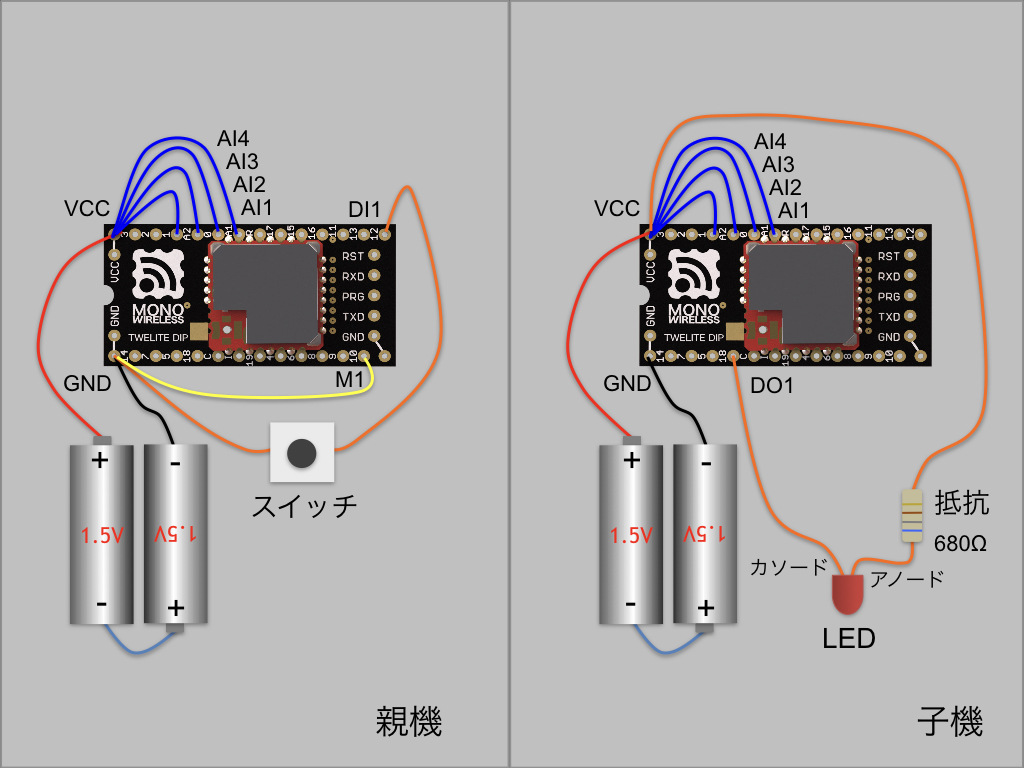
Example wiring (AI1-AI4 are optional)
// use twelite mwx c++ template library
#include <TWELITE>
#include <NWK_SIMPLE>
#include <BRD_APPTWELITE>
#include <STG_STD>
<TWELITE> is included in all acts. Here, we also include the simple network <NWK_SIMPLE> and the board support <BRD_APPTWELITE>.
Additionally, <STG_STD> is included to add interactive mode.
/*** Config part */
// application ID
const uint32_t DEFAULT_APP_ID = 0x1234abcd;
// channel
const uint8_t DEFAULT_CHANNEL = 13;
// option bits
uint32_t OPT_BITS = 0;
// logical id
uint8_t LID = 0;

/*** function prototype */
MWX_APIRET transmit();
void receive();

/*** application defs */
const char APP_FOURCHAR[] = "BAT1";

// sensor values
uint16_t au16AI[5];
uint8_t u8DI_BM;
setup()
void setup() {
	/*** SETUP section */
	// init vars
	for(auto&& x : au16AI) x = 0xFFFF;
	u8DI_BM = 0xFF;

	// load board and settings
	auto&& set = the_twelite.settings.use<STG_STD>();
	auto&& brd = the_twelite.board.use<BRD_APPTWELITE>();
	auto&& nwk = the_twelite.network.use<NWK_SIMPLE>();

	// settings: configure items
	set << SETTINGS::appname("BRD_APPTWELITE");
	set << SETTINGS::appid_default(DEFAULT_APP_ID); // set default appID
	set << SETTINGS::ch_default(DEFAULT_CHANNEL); // set default channel
	set.hide_items(E_STGSTD_SETID::OPT_DWORD2, E_STGSTD_SETID::OPT_DWORD3, E_STGSTD_SETID::OPT_DWORD4, E_STGSTD_SETID::ENC_KEY_STRING, E_STGSTD_SETID::ENC_MODE);
	set.reload(); // load from EEPROM.
	OPT_BITS = set.u32opt1(); // this value is not used in this example.
	LID = set.u8devid(); // logical ID

	// the twelite main class
	the_twelite
		<< set                      // apply settings (appid, ch, power)
		<< TWENET::rx_when_idle();  // open receive circuit (if not set, it can't listen packts from others)

	if (brd.get_M1()) { LID = 0; }

	// Register Network
	nwk << set // apply settings (LID and retry)
			;

	// if M1 pin is set, force parent device (LID=0)
	nwk << NWK_SIMPLE::logical_id(LID); // write logical id again.

	/*** BEGIN section */
	// start ADC capture
	Analogue.setup(true, ANALOGUE::KICK_BY_TIMER0); // setup analogue read (check every 16ms)
	Analogue.begin(pack_bits(
						BRD_APPTWELITE::PIN_AI1,
						BRD_APPTWELITE::PIN_AI2,
						BRD_APPTWELITE::PIN_AI3,
						BRD_APPTWELITE::PIN_AI4,
				   		PIN_ANALOGUE::VCC)); // _start continuous adc capture.

	// Timer setup
	Timer0.begin(32, true); // 32hz timer

	// start button check
	Buttons.setup(5); // init button manager with 5 history table.
	Buttons.begin(pack_bits(
						BRD_APPTWELITE::PIN_DI1,
						BRD_APPTWELITE::PIN_DI2,
						BRD_APPTWELITE::PIN_DI3,
						BRD_APPTWELITE::PIN_DI4),
					5, 		// history count
					4);  	// tick delta (change is detected by 5*4=20ms consequtive same values)


	the_twelite.begin(); // start twelite!

	/*** INIT message */
	Serial 	<< "--- BRD_APPTWELITE ---" << mwx::crlf;
	Serial	<< format("-- app:x%08x/ch:%d/lid:%d"
					, the_twelite.get_appid()
					, the_twelite.get_channel()
					, nwk.get_config().u8Lid
				)
			<< mwx::crlf;
	Serial 	<< format("-- pw:%d/retry:%d/opt:x%08x"
					, the_twelite.get_tx_power()
					, nwk.get_config().u8RetryDefault
					, OPT_BITS
			)
			<< mwx::crlf;
}
The general flow is initial setup of each part, followed by starting each part.
	auto&& set = the_twelite.settings.use<STG_STD>();
	auto&& brd = the_twelite.board.use<BRD_APPTWELITE>();
	auto&& nwk = the_twelite.network.use<NWK_SIMPLE>();
Register behavior objects to determine the system’s behavior. This includes interactive mode settings management, board support, and wireless packet network description.
setup().
// インタラクティブモードの初期化
auto&& set = the_twelite.settings.use<STG_STD>();

set << SETTINGS::appname("BRD_APPTWELITE");
set << SETTINGS::appid_default(DEFAULT_APP_ID); // set default appID
set << SETTINGS::ch_default(DEFAULT_CHANNEL); // set default channel
set.hide_items(E_STGSTD_SETID::OPT_DWORD2, E_STGSTD_SETID::OPT_DWORD3, E_STGSTD_SETID::OPT_DWORD4, E_STGSTD_SETID::ENC_KEY_STRING, E_STGSTD_SETID::ENC_MODE);
set.reload(); // load from EEPROM.
OPT_BITS = set.u32opt1(); // this value is not used in this example.
LID = set.u8devid(); // logical ID;
Initializes interactive mode. First, the set object is obtained. Then, the following processing is performed:
"BRD_APPTWELITE" (used in the menu)set.reload()OPT_BITS and LID to variablesBelow is an example screen. By entering + + + (three times, with intervals of 0.2 to 1 second), you can bring up the interactive mode screen.
[CONFIG/BRD_APPTWELITE:0/SID=8XXYYYYY]
a: (0x1234ABCD) Application ID [HEX:32bit]
i: (        13) Device ID [1-100,etc]
c: (        13) Channel [11-26]
x: (      0x03) RF Power/Retry [HEX:8bit]
o: (0x00000000) Option Bits [HEX:32bit]

 [ESC]:Back [!]:Reset System [M]:Extr Menu
the_tweliteThis object acts as the core of TWENET.
auto&& brd = the_twelite.board.use<BRD_APPTWELITE>();
Register the board (in this act, <BRD_APPTWELITE> is registered). Specify the board name you want to register after use with <>.
The return value obtained by universal reference (auto&&) is a reference type board object. This object includes board-specific operations and definitions. Below, the board object is used to check the state of the M1 pin. If the M1 pin is LOW, LID is set to 0, i.e., the parent address.
if (brd.get_M1()) { LID = 0; }
Initial settings are required to operate the_twelite. Setting the application ID and wireless channel is essential.
	// the twelite main class
	the_twelite
		<< set
		<< TWENET::rx_when_idle();  // open receive circuit (if not set, it can't listen packts from others)
Use << to reflect settings in the_twelite.
set reflects some of the settings read from interactive mode (such as application ID and wireless channel). For details on reflected items, see the explanation of <STG_STD>.TWENET::rx_when_idle() specifies to open the receive circuit.The << and >> operators are bit shift operators in C, but here they are used as stream insertion operators. In the MWX library, following the usage in the C++ standard library, they are used for settings, serial port I/O, and so on.
However, the following code cannot be used with the MWX library:
#include <iostream>
std::cout << "hello world" << std::endl;
次にネットワークを登録します。
auto&& nwk = the_twelite.network.use<NWK_SIMPLE>();
nwk << set;
nwk << NWK_SIMPLE::logical_id(LID);
The first line registers the network in the same way as the board, specifying <NWK_SIMPLE> in <>.
The second and third lines are settings for <NWK_SIMPLE>. First, the interactive mode settings are reflected. The reflected items are LID and the retry count. In this application, since LID may be set to 0 depending on the state of the M1 pin, LID is set again in the third line.
AnalogueThis is a class object that handles ADC (Analog-to-Digital Converter).
Analogue.setup(true, ANALOGUE::KICK_BY_TIMER0);
Initialization is done with Analogue.setup(). The parameter true specifies to wait until the ADC circuit is stabilized. The second parameter specifies to synchronize the start of ADC with Timer0.
	Analogue.begin(pack_bits(
						BRD_APPTWELITE::PIN_AI1,
						BRD_APPTWELITE::PIN_AI2,
						BRD_APPTWELITE::PIN_AI3,
						BRD_APPTWELITE::PIN_AI4,
				   	PIN_ANALOGUE::VCC));
To start ADC, call Analogue.begin(). The parameter is a bitmap corresponding to the ADC target pins.
The pack_bits() function is used to specify the bitmap. It is a variadic function, and each argument specifies the bit position to set to 1. For example, pack_bits(1,3,5) returns the value 101010 in binary. Since this function is marked constexpr, if the parameters are all constants, it will be expanded as a constant.
BRD_APPTWELITE:: defines PIN_AI1..4 as parameters. These correspond to AI1..AI4 used in App_Twelite. The assignments are AI1=ADC1, AI2=DIO0, AI3=ADC2, AI4=DIO2. PIN_ANALOGUE:: defines a list of pins available for ADC.
ButtonsDetects changes in the value of DIO (digital input). Buttons reduces the effect of mechanical button chattering, and only considers a value change after the same value has been detected a certain number of times.
Buttons.setup(5);
Initialization is done with Buttons.setup(). The parameter 5 specifies the maximum number of detections required to confirm the value. Internally, this number is used to allocate memory.
Buttons.begin(pack_bits(
						BRD_APPTWELITE::PIN_DI1,
						BRD_APPTWELITE::PIN_DI2,
						BRD_APPTWELITE::PIN_DI3,
						BRD_APPTWELITE::PIN_DI4),
					5, 		// history count
					4);  	// tick delta
Start is done with Buttons.begin(). The first parameter is the DIO to detect. Specify PIN_DI1-4 (DI1-DI4) defined in BRD_APPTWELITE::. The second parameter is the number of detections required to confirm the state. The third parameter is the detection interval. Since 4 is specified, when the same value is detected five times in a row every 4ms, the state is confirmed as HIGH or LOW.
Buttons is performed in the event handler. The event handler is called in the application loop after an interrupt occurs, so it has more delay compared to the interrupt handler.Timer0
Timer0.begin(32, true); // 32hz timer
In App_Twelite, application control is based on a timer, so this act also operates timer interrupts and events in the same way. Of course, you can also use the system TickTimer, which operates every 1ms.
In the example above, the first parameter is the timer frequency, set to 32Hz. The second parameter enables the software interrupt when set to true.
After calling Timer0.begin(), the timer starts running.
the_tweliteの動作開始
the_twelite.begin(); // start twelite!
At the end of the setup() function, the_twelite.begin() is executed.
SerialThe Serial object can be used without initialization or start procedures.
	Serial 	<< "--- BRD_APPTWELITE ---" << mwx::crlf;
	Serial	<< format("-- app:x%08x/ch:%d/lid:%d"
					, the_twelite.get_appid()
					, the_twelite.get_channel()
					, nwk.get_config().u8Lid
				)
			<< mwx::crlf;
	Serial 	<< format("-- pw:%d/retry:%d/opt:x%08x"
					, the_twelite.get_tx_power()
					, nwk.get_config().u8RetryDefault
					, OPT_BITS
			)
			<< mwx::crlf;
In this sample, several system settings are displayed as a startup message. The Serial object can take a const char* string, int type (other integer types are not accepted), format() which behaves almost like printf(), and crlf for newlines, all using the << operator.
mwx:: namespace is sometimes omitted. In the above, it is written as mwx::crlf, but you can also write simply crlf. The mwx:: namespace is designed to allow partial omission.loop()The loop function is called as a callback from the TWENET library’s main loop. The basic description here is to wait for the objects you use to become available and then process them. Below, we will explain the use of several objects used in this act.
The main loop of the TWENET library processes events such as received packets and interrupt information that have been stored in the FIFO queue in advance, and then calls loop(). After exiting loop(), the CPU enters DOZE mode and waits in low power consumption until a new interrupt occurs.
Therefore, code that assumes the CPU is always running will not work properly.
/*** loop procedure (called every event) */
void loop() {
	if (Buttons.available()) {
		uint32_t bp, bc;
		Buttons.read(bp, bc);

		u8DI_BM = uint8_t(collect_bits(bp,
							BRD_APPTWELITE::PIN_DI4,   // bit3
							BRD_APPTWELITE::PIN_DI3,   // bit2
							BRD_APPTWELITE::PIN_DI2,   // bit1
							BRD_APPTWELITE::PIN_DI1)); // bit0

		transmit();
	}

	if (Analogue.available()) {
		au16AI[0] = Analogue.read(PIN_ANALOGUE::VCC);
		au16AI[1] = Analogue.read_raw(BRD_APPTWELITE::PIN_AI1);
		au16AI[2] = Analogue.read_raw(BRD_APPTWELITE::PIN_AI2);
		au16AI[3] = Analogue.read_raw(BRD_APPTWELITE::PIN_AI3);
		au16AI[4] = Analogue.read_raw(BRD_APPTWELITE::PIN_AI4);
	}

	if (Timer0.available()) {
		static uint8_t u16ct;
		u16ct++;

		if (u8DI_BM != 0xFF && au16AI[0] != 0xFFFF) { // finished the first capture
			if ((u16ct % 32) == 0) { // every 32ticks of Timer0
				transmit();
			}
		}
	}
}
ButtonsWhen a change in DIO (Digital IO) input is detected, it becomes available, and you can read it using Buttons.read().
	if (Buttons.available()) {
		uint32_t bp, bc;
		Buttons.read(bp, bc);
The first parameter is the current bitmap of DIO HIGH/LOW states, with bit0 corresponding to DIO0, bit1 to DIO1, and so on. For example, for DIO12, you can check if it is HIGH or LOW by evaluating bp & (1UL << 12). Bits set to 1 indicate HIGH.
Next, the value is extracted from the bitmap and stored in u8DI_BM. Here, we use the collect_bits() function provided by the MWX library.
u8DI_BM = uint8_t(collect_bits(bp,
		BRD_APPTWELITE::PIN_DI4,   // bit3
		BRD_APPTWELITE::PIN_DI3,   // bit2
		BRD_APPTWELITE::PIN_DI2,   // bit1
		BRD_APPTWELITE::PIN_DI1)); // bit0

/* collect_bits performs the following:
u8DI_BM = 0;
if (bp & (1UL << BRD_APPTWELITE::PIN_DI1)) u8DI_BM |= 1;
if (bp & (1UL << BRD_APPTWELITE::PIN_DI2)) u8DI_BM |= 2;
if (bp & (1UL << BRD_APPTWELITE::PIN_DI3)) u8DI_BM |= 4;
if (bp & (1UL << BRD_APPTWELITE::PIN_DI4)) u8DI_BM |= 8;
*/
collect_bits() takes integer values representing bit positions, just like the pack_bits() mentioned earlier. It is a variadic function, so you can specify as many parameters as needed. In the above process, bit0 is DI1, bit1 is DI2, bit2 is DI3, and bit3 is DI4, and the result is stored in u8DI_BM.
In App_Twelite, a wireless transmission occurs when there is a change in DI1 to DI4, so the transmission process is triggered by Buttons.available(). The contents of the transmit() process are described later.
transmit();
AnalogueAfter the ADC (Analog-to-Digital Converter) conversion is completed, Analogue becomes available in the next loop(). Until the next ADC starts, you can read the data as the most recently obtained value.
// After ADC conversion is completed, Analogue becomes available in loop().
// Until the next ADC starts, you can read the most recent value.
To read ADC values, use the Analogue.read() or Analogue.read_raw() methods. read() returns the value converted to mV, while read_raw() returns the ADC value in the range 0..1023. Specify the ADC pin number as a parameter. ADC pin numbers are defined in PIN_ANALOGUE:: or BRD_APPTWELITE::, so use those.
Since ADC is executed periodically, depending on the timing, you may read a newer value than the one notified by available.
In this act, because processing is done at a relatively slow cycle of 32Hz, there is no problem if you process immediately after available is true. However, if the conversion cycle is short or if you have processing in loop() that takes a relatively long time, be careful.
Analogue allows you to specify a callback function that is called from within the interrupt handler after conversion is completed. For example, you can use this callback function to store values in a FIFO queue, and then read the values sequentially in the application loop for asynchronous processing.
Timer0Timer0 operates at 32Hz. It becomes available in loop() immediately after a timer interrupt occurs. In other words, processing is done 32 times per second. Here, the transmission process is performed exactly once per second.
if (Timer0.available()) {
	static uint8_t u16ct;
	u16ct++;

	if (u8DI_BM != 0xFF && au16AI[0] != 0xFFFF) { // finished the first capture
		if ((u16ct % 32) == 0) { // every 32ticks of Timer0
			transmit();
		}
	}
}
AppTwelite sends periodically about once per second. When Timer0 becomes available, u16ct is incremented. Based on this counter value, after counting 32 times, transmit() is called to send a wireless packet.
The value checks for u8DI_BM and au16AI[] are to determine whether it is right after initialization. If the values for DI1..DI4 or AI1..AI4 have not yet been stored, nothing is done.
transmit()This function issues a request to TWENET to transmit a wireless packet. When this function returns, the wireless packet has not yet been processed. Actual transmission will be completed several milliseconds later, depending on the transmission parameters. Here, typical transmission request methods are explained.
MWX_APIRET transmit() {
	if (auto&& pkt = the_twelite.network.use<NWK_SIMPLE>().prepare_tx_packet()) {
	  auto&& set = the_twelite.settings.use<STG_STD>();
		if (!set.is_screen_opened()) {
			Serial << "..DI=" << format("%04b ", u8DI_BM);
			Serial << format("ADC=%04d/%04d/%04d/%04d ", au16AI[1], au16AI[2], au16AI[3], au16AI[4]);
			Serial << "Vcc=" << format("%04d ", au16AI[0]);
			Serial << " --> transmit" << mwx::crlf;
		}

		// set tx packet behavior
		pkt << tx_addr(u8devid == 0 ? 0xFE : 0x00)  // 0..0xFF (LID 0:parent, FE:child w/ no id, FF:LID broad cast), 0x8XXXXXXX (long address)
			<< tx_retry(0x1) // set retry (0x1 send two times in total)
			<< tx_packet_delay(0,50,10); // send packet w/ delay (send first packet with randomized delay from 100 to 200ms, repeat every 20ms)

		// prepare packet payload
		pack_bytes(pkt.get_payload() // set payload data objects.
			, make_pair(APP_FOURCHAR, 4) // string should be paired with length explicitly.
			, uint8_t(u8DI_BM)
		);

		for (auto&& x : au16AI) {
			pack_bytes(pkt.get_payload(), uint16_t(x)); // adc values
		}

		// do transmit
		return pkt.transmit();
	}
	return MWX_APIRET(false, 0);
}
MWX_APIRET transmit()
MWX_APIRET is a class that handles return values with a uint32_t data member. The MSB (bit31) indicates success or failure, and the other bits are used as the return value.
if (auto&& pkt = the_twelite.network.use<NWK_SIMPLE>().prepare_tx_packet()) {
Obtain the network object with the_twelite.network.use<NWK_SIMPLE>(). Then use that object to obtain the pkt object with .prepare_tx_packet().
Here, it is declared within the condition of the if statement. The declared pkt object is valid until the end of the if block. The pkt object responds as a bool type: it is true if the TWENET transmission request queue has space to accept the request, and false if there is no space.
auto&& set = the_twelite.settings.use<STG_STD>();
if (!set.is_screen_opened()) {
    // Not in interactive mode screen!
}
Output is suppressed when the interactive mode screen is displayed.
pkt << tx_addr(u8devid == 0 ? 0xFE : 0x00)  // 0..0xFF (LID 0:parent, FE:child w/ no id, FF:LID broad cast), 0x8XXXXXXX (long address)
		<< tx_retry(0x1) // set retry (0x3 send four times in total)
		<< tx_packet_delay(0,50,10); // send packet w/ delay (send first packet with randomized delay from 100 to 200ms, repeat every 20ms)
Packet settings are configured using the << operator, similar to the initialization settings of the_twelite.
tx_addr(): Specifies the destination address. If 0x00, it means sending from a child to the parent; if 0xFE, it means sending from a parent as a broadcast to any child.tx_retry(): Specifies the number of retransmissions. For example, 1 means retransmit once, so two packets in total are sent. Even in good conditions, sending a wireless packet only once can result in a few percent failure rate.tx_packet_delay(): Sets the transmission delay. The first parameter is the minimum waiting time before transmission starts, the second is the maximum waiting time. In this case, after issuing the transmission request, the transmission starts at a random time between 0 and 50 ms. The third parameter is the retransmission interval. It means retransmitting every 10 ms after the first packet is sent.Payload means “cargo,” but in wireless packets it often refers to the “main data you want to send.” Wireless packets also contain auxiliary information such as address information, in addition to the main data.
To ensure correct transmission and reception, pay attention to the order of data in the payload. Here, the following data order is used. Construct the data payload according to this order.
# Index of the first byte: Data type : Byte size : Content

00: uint8_t[4] : 4 : 4-character identifier
04: uint8_t    : 1 : Bitmap of DI1..4
06: uint16_t   : 2 : Vcc voltage value
08: uint16_t   : 2 : AI1 ADC value (0..1023)
10: uint16_t   : 2 : AI2 ADC value (0..1023)
12: uint16_t   : 2 : AI3 ADC value (0..1023)
14: uint16_t   : 2 : AI4 ADC value (0..1023)
Up to 90 bytes can be stored in the data payload (in reality, a few more bytes can fit).
In IEEE802.15.4 wireless packets, every byte is valuable. It is recommended to use them as sparingly as possible. There is a limit to the amount of data that can be sent in one packet. If you split the data into multiple packets, you must consider the cost and risk of packet loss. Also, sending one extra byte consumes energy equivalent to about 16μs times the transmission current, which greatly affects battery-powered applications.
The above example makes some compromises for explanation purposes. If you want to save data, the identifier at 00: should be a simple one-byte value, and the VCC voltage can be rounded to 8 bits. Also, the values for AI1..AI4 are 10 bits each, so while the total is 40 bits (5 bytes), 6 bytes are actually used.
Let’s actually construct the data structure of the payload described above. The data payload can be referenced as a simplbuf<uint8_t> container via pkt.get_payload(). Build the data in this container according to the above specifications.
auto&& payl = pkt.get_payload();
payl.reserve(16); // resize to 16 bytes
payl[00] = APP_FOURCHAR[0];
payl[01] = APP_FOURCHAR[1];
...
payl[08] = (au16AI[0] & 0xFF00) >> 8; //Vcc
payl[09] = (au16AI[0] & 0xFF);
...
payl[14] = (au16AI[4] & 0xFF00) >> 8; // AI4
payl[15] = (au16AI[4] & 0xFF);
You can write it as shown above, but the MWX library provides a helper function pack_bytes() for constructing the data payload.
// prepare packet payload
pack_bytes(pkt.get_payload() // set payload data objects.
	, make_pair(APP_FOURCHAR, 4) // string should be paired with length explicitly.
	, uint8_t(u8DI_BM)
);

for (auto&& x : au16AI) {
	pack_bytes(pkt.get_payload(), uint16_t(x)); // adc values
}
The first parameter of pack_bytes() specifies the container, in this case pkt.get_payload().
The following parameters are variadic arguments, and you specify as many values of supported types as needed. Internally, pack_bytes() calls the .push_back() method to append the specified values to the end.
On the third line, make_pair() is a standard library function that generates a std::pair. This is specified to avoid confusion with string types (specifically, whether or not to include null characters in the payload). The first parameter of make_pair() should be a string type (such as char*, uint8_t*, or uint8_t[]). The second parameter is the number of bytes to be stored in the payload.
On the fourth line, the bitmap of DI1..DI4 is written as a uint8_t.
On lines 7-9, the values of the au16AI array are written sequentially. These values are of uint16_t type (2 bytes), and are written in big-endian order.
The for statement on line 7 is a C++ range-based for loop. This syntax can be used for arrays of known size and container classes that support access via begin() and end() iterators. The type of au16AI can also be determined at compile time, so type specification is omitted using auto&& (universal reference).
If rewritten as a normal for loop, it would look like the following:
for(int i = 0; i < sizeof(au16AI)/sizeof(uint16_t)); i++) {
  pack_bytes(pkt.get_payload(), au16AI[i]);
}
With this, preparation of the packet is complete. Now, simply issue the transmission request.
return pkt.transmit();
To send the packet, use the pkt.transmit() method of the pkt object. The return value is of type MWX_APIRET, but it is not used in this act.
on_rx_packet()When a wireless packet is received, the reception event on_rx_packet() is called.
the_twelite.receiver, received packets were temporarily stored in an internal queue (up to two packets) before processing, but with on_rx_packet(), it is called directly from the callback of the TWENET library, making it less likely for packets to be missed. However, if processing inside the loop() statement is blocked for a long time, packets may still be missed for the same reason.Here, the values of DI1..DI4 and AI1..AI4 received from the other party are set to the local DO1..DO4 and PWM1..PWM4.
void on_rx_packet(packet_rx& rx, bool_t &handled) {
	auto&& set = the_twelite.settings.use<STG_STD>();

	Serial << format("..receive(%08x/%d) : ", rx.get_addr_src_long(), rx.get_addr_src_lid());

  // expand the packet payload
	char fourchars[5]{};
	auto&& np = expand_bytes(rx.get_payload().begin(), rx.get_payload().end()
		, make_pair((uint8_t*)fourchars, 4)  // 4bytes of msg
    );

	// check header
	if (strncmp(APP_FOURCHAR, fourchars, 4)) { return; }

	// read rest of payload
	uint8_t u8DI_BM_remote = 0xff;
	uint16_t au16AI_remote[5];
	expand_bytes(np, rx.get_payload().end()
		, u8DI_BM_remote
		, au16AI_remote[0]
		, au16AI_remote[1]
		, au16AI_remote[2]
		, au16AI_remote[3]
		, au16AI_remote[4]
	);

	Serial << format("DI:%04b", u8DI_BM_remote & 0x0F);
	for (auto&& x : au16AI_remote) {
		Serial << format("/%04d", x);
	}
	Serial << mwx::crlf;

	// set local DO
	digitalWrite(BRD_APPTWELITE::PIN_DO1, (u8DI_BM_remote & 1) ? HIGH : LOW);
	digitalWrite(BRD_APPTWELITE::PIN_DO2, (u8DI_BM_remote & 2) ? HIGH : LOW);
	digitalWrite(BRD_APPTWELITE::PIN_DO3, (u8DI_BM_remote & 4) ? HIGH : LOW);
	digitalWrite(BRD_APPTWELITE::PIN_DO4, (u8DI_BM_remote & 8) ? HIGH : LOW);

	// set local PWM : duty is set 0..1024, so 1023 is set 1024.
	Timer1.change_duty(au16AI_remote[1] == 1023 ? 1024 : au16AI_remote[1]);
	Timer2.change_duty(au16AI_remote[2] == 1023 ? 1024 : au16AI_remote[2]);
	Timer3.change_duty(au16AI_remote[3] == 1023 ? 1024 : au16AI_remote[3]);
	Timer4.change_duty(au16AI_remote[4] == 1023 ? 1024 : au16AI_remote[4]);
}
void on_rx_packet(packet_rx& rx, bool_t &handled)
The received packet data rx is passed as a parameter. From rx, you can access the address information and data payload of the wireless packet. The handled parameter is not typically used.
if (!set.is_screen_opened()) {
   Serial << format("..receive(%08x/%d) : ",
      rx.get_addr_src_long(), rx.get_addr_src_lid());
}
The received packet data refers to information such as the source address (32-bit long address and 8-bit logical address). Output is suppressed when the interactive mode screen is displayed.
<NWK_SIMPLE>, both an 8-bit logical ID and a 32-bit long address are always exchanged. When specifying a destination, either the long address or logical address is used. Both addresses are included upon reception.The MWX library provides the function expand_bytes(), which is the counterpart to pack_bytes() used in transmit().
char fourchars[5]{};
auto&& np = expand_bytes(rx.get_payload().begin(), rx.get_payload().end()
	, make_pair((uint8_t*)fourchars, 4)  // 4bytes of msg
  );
The first line declares a char array to store the data. The size is 5 bytes in order to include a null terminator for convenience in character output. The trailing {} is an initializer; although you could simply set the fifth byte to zero, here the entire array is initialized to zero by default.
On the second line, a 4-byte string is extracted using expand_bytes(). The reason for not specifying a container type as a parameter is to keep track of the read position for subsequent extraction. The first parameter specifies the beginning iterator (a uint8_t* pointer) of the container, obtained with the .begin() method. The second parameter is the iterator just past the end of the container, obtained with the .end() method. This ensures that reads do not exceed the end of the container.
For the third argument, specify the variable to read into, again using make_pair() to specify the string array and its size as a pair.
expand_bytes() for validation.
The return value of expand_bytes() is a uint8_t*; if you attempt to read past the end, it returns nullptr.If the identifier in the extracted 4-byte string differs from the one specified in this act, the packet is ignored.
if (strncmp(APP_FOURCHAR, fourchars, 4)) { return; }
<NWK_SIMPLE>. Unless another application not using the simple network defines the exact same packet structure (which is extremely rare), mixed reception of packets should not occur.Store the values of DI1..DI4 and AI1..AI4 into separate variables.
	// read rest of payload
	uint8_t u8DI_BM_remote = 0xff;
	uint16_t au16AI_remote[5];
	expand_bytes(np, rx.get_payload().end()
		, u8DI_BM_remote
		, au16AI_remote[0]
		, au16AI_remote[1]
		, au16AI_remote[2]
		, au16AI_remote[3]
		, au16AI_remote[4]
	);
Here, the return value np from the earlier expand_bytes() call is used as the first parameter, indicating that reading should start from immediately after the 4-byte identifier just extracted. The second parameter is handled in the same way.
The third and subsequent parameters specify variables whose types and order correspond to those in the payload, matching the data structure on the sender side. When this process is complete, the extracted values from the payload are stored in the specified variables.
For confirmation, the data is output to the serial port. Output is suppressed when the interactive mode screen is displayed.
auto&& set = the_twelite.settings.use<STG_STD>();
...
Serial << format("DI:%04b", u8DI_BM_remote & 0x0F);
for (auto&& x : au16AI_remote) {
	Serial << format("/%04d", x);
}
Serial << mwx::crlf;
The format() function is used for numeric formatting. It is a helper class that enables the use of printf-style syntax for the >> operator, but it is limited to four arguments (there is no such limit with Serial.printfmt()).
On the third line, "DI:%04b" displays the bitmap of DI1..DI4 in four digits, e.g., “DI:0010”.
On the fifth line, "/%04d" outputs the values of Vcc and AI1..AI4 sequentially as integers, such as “/3280/0010/0512/1023/1023”.
On the seventh line, mwx::crlf outputs a newline character.
Once the required data is extracted, update the values of DO1..DO4 and PWM1..PWM4 on the board.
// set local DO
digitalWrite(BRD_APPTWELITE::PIN_DO1, (u8DI_BM_remote & 1) ? HIGH : LOW);
digitalWrite(BRD_APPTWELITE::PIN_DO2, (u8DI_BM_remote & 2) ? HIGH : LOW);
digitalWrite(BRD_APPTWELITE::PIN_DO3, (u8DI_BM_remote & 4) ? HIGH : LOW);
digitalWrite(BRD_APPTWELITE::PIN_DO4, (u8DI_BM_remote & 8) ? HIGH : LOW);

// set local PWM : duty is set 0..1024, so 1023 is set 1024.
Timer1.change_duty(au16AI_remote[1] == 1023 ? 1024 : au16AI_remote[1]);
Timer2.change_duty(au16AI_remote[2] == 1023 ? 1024 : au16AI_remote[2]);
Timer3.change_duty(au16AI_remote[3] == 1023 ? 1024 : au16AI_remote[3]);
Timer4.change_duty(au16AI_remote[4] == 1023 ? 1024 : au16AI_remote[4]);
digitalWrite() changes the value of a digital output. The first parameter is the pin number; the second specifies either HIGH (VCC level) or LOW (GND level).
Timer?.change_duty() changes the PWM output duty cycle. Specify the duty as a value between 0..1024. Note that the maximum value is not 1023. Since division operations within the library are computationally expensive, a power of two (1024) is used as the maximum value. Setting the parameter to 0 outputs GND level; setting it to 1024 outputs VCC level.
This sample uses the I2C sensor device mounted on our AMBIENT SENSE PAL or TWELITE ARIA BLUE / RED. However, by rewriting the I2C command send/receive section, you can use other general-purpose I2C sensor devices (shown as Generic I2C Sensor Module in the diagram). In that case, please wire as shown below.
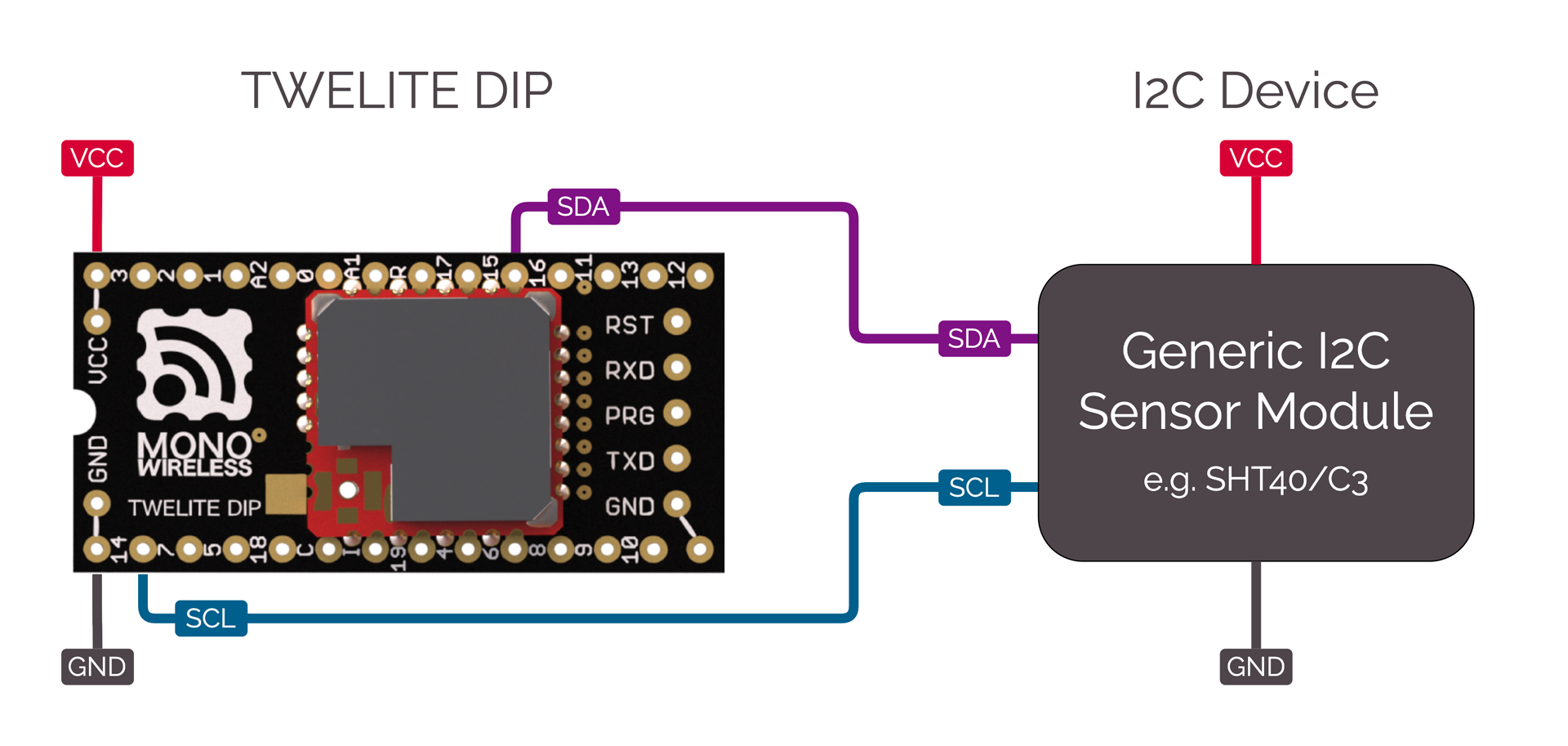
Connection of a generic I2C device
This act includes the following:
<STG_STD><SM_SIMPLE>| Role | Example |
|---|---|
| Parent | MONOSTICK BLUE / REDRun act Parent_MONOSTICK. |
| Child | - BLUE / RED PAL + AMBIENT SENSE PAL- TWELITE ARIA BLUE / RED |
#include <TWELITE>
#include <NWK_SIMPLE>// ネットワークサポート
#include <STG_STD>   // インタラクティブモード
#include <SM_SIMPLE> // 簡易ステートマシン
<NWK_SIMPLE> is required for wireless communication, <STG_STD> adds interactive mode, and <SM_SIMPLE> is included to simplify the application loop description.
In this example, there are two types of code: SHTC3 (TWELITE AMB PAL) and SHT40 (TWELITE ARIA), which are switched using #ifdef (please #define either USE_SHTC3 or USE_SHT40). For portability, both types are defined with the same function interface. Since both sensors are from the same manufacturer and series, the code is similar.
/*** sensor select, define either of USE_SHTC3 or USE_SHT40  */
// use SHTC3 (TWELITE PAL)
#define USE_SHTC3
// use SHT40 (TWELITE ARIA)
#undef USE_SHT40
以下では SHTC3 の例を示します。
#if defined(USE_SHTC3)
// for SHTC3
struct SHTC3 {
	uint8_t I2C_ADDR;
	uint8_t CONV_TIME;

    bool setup() { ... }
	bool begin() { ... }
	int get_convtime() { return CONV_TIME; }
	bool read(int16_t &i16Temp, int16_t &i16Humd) { ... }
} sensor_device;
Here, the I2C sensor-related procedures are organized into the SHTC3 struct (class) for clarity. This struct has member variables for the I2C address I2C_ADDR and the wait time for acquiring values CONV_TIME, and is declared with the instance name sensor_device.
This struct (class) has the following member functions:
| Function Name | Description |
|---|---|
setup() | Initializes the struct. |
begin() | Starts acquiring sensor values.After starting, you must wait a certain period for valid sensor values. |
get_convtime() | Returns the sensor value acquisition wait time. |
read(int&, int&) | Acquires the sensor values. |
setup() instead of the constructor.Let’s look at each process step by step.
setup()
bool setup() {
	// here, initialize some member vars instead of constructor.
	I2C_ADDR = 0x70;
	CONV_TIME = 10; // wait time [ms]
	return true;
}
Set the I2C address and the sensor value acquisition wait time (10ms above) to the member variables.
These values are basically fixed, so you do not need to set them as variables. Valid examples for treating them as variables include cases where you want to manage conversion time for higher-precision sensor operation depending on settings, or select a sub-address for I2C depending on configuration.
begin()
bool begin() {
	// send start trigger command
	if (auto&& wrt = Wire.get_writer(I2C_ADDR)) {
		wrt << 0x60; // SHTC3_TRIG_H
		wrt << 0x9C; // SHTC3_TRIG_L
	} else {
		return false;
	}
	return true;
}
Writes a command to operate the sensor.
The MWX library provides two different ways to read/write the I2C bus using the Wire class object; this is the helper function method.
In the if statement, Wire.get_writer(I2C_ADDR) opens the I2C device at address I2C_ADDR and generates a read/write object. The read/write object wrt returns false if the device fails to open (evaluated as (bool) in the if statement). If true, it means it opened successfully and the processing inside the if block is performed.
Here, wrt << 0x60; writes a byte to the I2C device using the stream operator <<. This operator is basically for writing a single byte of type uint8_t.
get_convtime()
int get_convtime() {
	return CONV_TIME;
}
This function returns the value of CONV_TIME.
read()
bool read(int16_t &i16Temp, int16_t &i16Humd) {
	// read result
	uint16_t u16temp, u16humd;
	uint8_t u8temp_csum, u8humd_csum;
	if (auto&& rdr = Wire.get_reader(I2C_ADDR, 6)) {
		rdr >> u16temp;      // read two bytes (MSB first)
		rdr >> u8temp_csum;  // check sum (crc8)
		rdr >> u16humd;      // read two bytes (MSB first)
		rdr >> u8humd_csum;  // check sum (crc8)
	} else {
		return false;
	}

	// check CRC and save the values
	if (   (CRC8_u8CalcU16(u16temp, 0xff) == u8temp_csum)
		&& (CRC8_u8CalcU16(u16humd, 0xff) == u8humd_csum))
	{
		i16Temp = (int16_t)(-4500 + ((17500 * int32_t(u16temp)) >> 16));
		i16Humd = (int16_t)((int32_t(u16humd) * 10000) >> 16);
	} else {
		return false;
	}

	return true;
}
Reads the sensor data.
For SHTC3, after starting sensor readout with begin(), you wait a few ms and then read the sensor values. The arrangement of sensor values is as follows:
| Byte | Description |
|---|---|
| 0 | Temperature sensor value (upper byte) |
| 1 | Temperature sensor value (lower byte) |
| 2 | CRC8 value for bytes 0,1 |
| 3 | Humidity sensor value (upper byte) |
| 4 | Humidity sensor value (lower byte) |
| 5 | CRC8 value for bytes 3,4 |
0x609C command written in begin() above, the temperature data arrives first.In begin(), data was written, but here, data is read. To read data, similarly generate a helper object rdr using Wire.get_reader(). If there are no errors, rdr returns true in the if block. The second parameter 6 in get_reader(I2C_ADDR, 6) is the number of bytes to read. When this number of bytes has been read, the I2C bus readout process ends. (Depending on the device, you may omit this, but usually you should provide the appropriate value.)
Reading is done with the stream operator >>. There are other ways to read; for details, see helper functions. When using the stream operator, you input values into pre-declared variables of type uint8_t, uint16_t, or uint32_t. rdr >> u16temp reads two bytes from the I2C bus into a uint16_t variable in big-endian format (first byte is upper byte).
Finally, i16Temp and i16Humd are calculated and stored as 100 times the temperature [°C] and 100 times the humidity [%], respectively. For the calculation formulas, refer to the I2C device datasheet.
setup()The setup() function is called only once when TWELITE starts. This function performs various initializations.
void setup() {
	/*** SETUP section */
	...
}
SM_SIMPLE Initialization
// application state defs
enum class STATE : uint8_t {
	INTERACTIVE = 255,
	INIT = 0,
	SENSOR,
	TX,
	TX_WAIT_COMP,
	GO_SLEEP
};

// simple state machine.
SM_SIMPLE<STATE> step;

void setup() {
	...
	/// init vars or objects
	step.setup(); // initialize state machine
	...
}
The state machine is used to simplify the description in the loop() statement, which is called repeatedly. Of course, you do not have to use SM_SIMPLE to describe your application.
SM_SIMPLE is implemented in very short code, and allows easy management of state transitions, timeouts, and flags. The states are defined in advance as an enumeration. In the example above, it’s enum class STATE. The state machine instance is declared as SM_SIMPLE<STATE> step using the defined STATE enum as a parameter.
void setup() {
	...
	/// load board and settings objects
	auto&& set = the_twelite.settings.use<STG_STD>(); // load save/load settings(interactive mode) support
	auto&& nwk = the_twelite.network.use<NWK_SIMPLE>(); // load network support
	...
}
Behavior is a set of functions used in the program. It describes what to do when various events occur.
Here, two behaviors are used: the interactive mode screen <STG_STD> and the simple relay network <NWK_SIMPLE>.
STG_STD
	...
	/// configure settings
	// configure settings
	set << SETTINGS::appname(FOURCHARS);
	set << SETTINGS::appid_default(DEFAULT_APP_ID); // set default appID
	set << SETTINGS::ch_default(DEFAULT_CHANNEL); // set default channel
	set.hide_items(E_STGSTD_SETID::OPT_DWORD2, E_STGSTD_SETID::OPT_DWORD3, E_STGSTD_SETID::OPT_DWORD4, 	E_STGSTD_SETID::ENC_KEY_STRING, E_STGSTD_SETID::ENC_MODE);
Initial settings are made for STG_STD so that the interactive mode setting items match the application being described.
SETTINGS::appname: Specifies the application name (string). Displayed on the first line in the interactive mode screen. Keep the string short as there is little space on the screen.SETTINGS::appid_default: Default application ID. Use this if you want to set a custom default application ID for your own application.SETTINGS::ch_default: Default channel. Use this if you want to set a custom default channel for your own application.Next, set.hide_items() removes unnecessary setting items from the default interactive mode screen. If you don’t mind displaying everything, you don’t need this call.
	// if SET(DIO12)=LOW is detected, start with intaractive mode.
	if (digitalRead(PIN_DIGITAL::DIO12) == PIN_STATE::LOW) {
		set << SETTINGS::open_at_start();
		step.next(STATE::INTERACTIVE);
		return;
	}
If the DIO12 pin is LOW (GND level) when power is applied or reset, this code starts in interactive mode. It reads the pin state with digitalRead() and applies SETTINGS::open_at_start().
To prevent normal application processing from running during interactive mode, the state machine is set to STATE::INTERACTIVE. In this state, no input or other processing is performed, and it remains in the same state.
	// load values
	set.reload(); // load from EEPROM.
	OPT_BITS = set.u32opt1(); // this value is not used in this example.

	// LID is configured DIP or settings.
	LID = set.u8devid(); // 2nd is setting.
	if (LID == 0) LID = 0xFE; // if still 0, set 0xFE (anonymous child)
Finally, the data for interactive mode is loaded. Calling set.reload() reads data written to EEPROM. If no settings were made and EEPROM has no information, default values are used.
Here, the option bits (set.u32opt1()) and 8-bit logical ID (set.u8devid()) are read. If LID is 0, it is usually operated as a parent, so if this value is recorded, it is set to 0xFE (child with no assigned ID).
	/// configure system basics
	the_twelite << set; // apply settings (from interactive mode)
	nwk << set; // apply settings (from interactive mode)
	nwk << NWK_SIMPLE::logical_id(LID); // set LID again (LID can also be configured by DIP-SW.)
	...
Finally, the configuration information (part of it) is applied to the_twelite and nwk. Essential information for wireless communication, such as application ID and channel, is reflected. There is no explicit code above for reading these settings, but with set.reload(), default values are used if there are no settings, and configured values are loaded if present.
	/*** BEGIN section */
	Wire.begin(); // start two wire serial bus.
This initializes the I2C sensor settings.
	// let the TWELITE begin!
	the_twelite.begin();

	/*** INIT message */
	Serial << "--- TEMP&HUMID:" << FOURCHARS << " ---" << mwx::crlf;
	Serial	<< format("-- app:x%08x/ch:%d/lid:%d"
					, the_twelite.get_appid()
					, the_twelite.get_channel()
					, nwk.get_config().u8Lid
				)
			<< mwx::crlf;
	Serial 	<< format("-- pw:%d/retry:%d/opt:x%08x"
					, the_twelite.get_tx_power()
					, nwk.get_config().u8RetryDefault
					, OPT_BITS
			)
			<< mwx::crlf;
the_twelite.begin() declares the completion of MWX library initialization. If you do not perform this process, the MWX library will not operate properly.
Startup messages, etc. are also displayed here.
loop()
void loop() {
	do {
		switch (step.state()) {
		 // 各状態の振る舞い
		case STATE::INIT:
		...
		break;
		...
		}
	while(step.b_more_loop());
}
The loop() uses the SM_SIMPLE state machine step for control. This is to concisely represent the flow from wakeup from sleep, sensor value acquisition, wireless packet transmission, waiting for transmission completion, and sleeping.
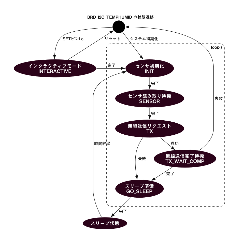
State machine diagram
The above do while control structure is described here. The state is determined by step.state(). The while condition is step.b_more_loop(). This is because, when transitioning from one state to another, you may want to process continuously without exiting loop(). In other words, when transitioning to another state and exiting the switch block, the next state’s case block is called. Be careful with this behavior.
case STATE::INTERACTIVE:Because it is undesirable for the main loop to run during interactive mode, it is fixed to this state.
case STATE::INIT:
// start sensor capture
sensor_device.begin();
step.set_timeout(sensor_device.get_convtime()); // set timeout
step.next(STATE::SENSOR);
Starts sensor data acquisition. set_timeout() is used to wait for the sensor acquisition time.
For sensors with a very long wait time, you could describe a process here to sleep temporarily, which would extend battery life, but this is omitted in this example for simplicity. If needed, refer to the example for sleep waiting.
case STATE::SENSOR:
if (step.is_timeout()) {
	// the sensor data should be ready (wait some)
	sensor_device.read(sensor.i16temp, sensor.i16humid);

	Serial << "..finish sensor capture." << mwx::crlf
		<< "     : temp=" << div100(sensor.i16temp) << 'C' << mwx::crlf
		<< "       humd=" << div100(sensor.i16humid) << '%' << mwx::crlf
		;
	Serial.flush();

	step.next(STATE::TX);
}
Acquire sensor values using sensor_device.read() and store them in the sensor struct.
First, a timeout check is performed using step.is_timeout(). The starting point for the timeout is the earlier step.set_timeout(). If not timed out, the if block is not executed, and loop() exits as is. Until the next hardware event (usually an interrupt from the TickTimer system timer every 1ms), the TWELITE microcontroller is in low-power DOZE mode with the CPU waiting.
As a wireless sensor, it is not necessary to output the results to the serial port of the sensor-side TWELITE, but for easy operation confirmation, the acquired values are displayed on the serial port. Here, Serial.flush() is used to wait for output, assuming that serial port output may not finish before TWELITE goes to sleep. This process can also cause battery drain, so you may want to avoid using Serial.flush() or not output to the serial port.
The div100() function used here performs division by 100 at low cost. Since TWELITE has no division circuit, it is recommended to avoid division processing as much as possible.
case STATE::TX:
step.next(STATE::GO_SLEEP); // set default next state (for error handling.)

// get new packet instance.
if (auto&& pkt = the_twelite.network.use<NWK_SIMPLE>().prepare_tx_packet()) {
	...
}
Describes the communication procedure. No waiting is done in this state; after executing the process, it promptly transitions to the next state. The preemptive step.next(STATE::GO_SLEEP) is written to avoid having to write the same code in every place where errors are detected, as errors may be detected in multiple locations.
if (auto&& pkt = the_twelite.network.use<NWK_SIMPLE>().prepare_tx_packet()) creates a transmit packet object, and if successful, the if block is executed.
// set tx packet behavior
pkt << tx_addr(0x00)  // 0..0xFF (LID 0:parent, FE:child w/ no id, FF:LID broad cast), 0x8XXXXXXX (long address)
	<< tx_retry(0x1) // set retry (0x1 send two times in total)
	<< tx_packet_delay(0, 0, 2); // send packet w/ delay
First, transmission settings are made. The destination tx_addr(0x00) is set to parent 0x00, the number of retries tx_retry(0x1) is set to 1, and the packet delay setting tx_packet_delay(0, 0, 2) sets the initial delay to 0 and the retransmission interval to 2ms.
pack_bytes(pkt.get_payload()
	, make_pair(FOURCHARS, 4)
	, uint16_t(sensor.i16temp)
	, uint16_t(sensor.i16humid)
	);
Stores the identifier FOURCHARS and sensor data in the payload section of the packet. The obtained temperature value is int16_t, but since the transmit packet data structure stores it unsigned, it is cast to uint16_t.
// do transmit
MWX_APIRET ret = pkt.transmit();

if (ret) {
	step.clear_flag(); // waiting for flag is set.
	step.set_timeout(100); // set timeout
	step.next(STATE::TX_WAIT_COMP);}
Calling pkt.transmit() requests transmission. At this point, transmission does not start yet; the request is just placed in the internal queue. The MWX library processes the request at the appropriate timing.
If the transmit request succeeds, ret is true. To judge completion, the flag is initialized with step.clear_flag(), a timeout is set with step.set_timeout(100) to handle unexpected errors such as transmission failure, and the next state is set to STATE::TX_WAIT_COMP (overwriting the previously set STATE::GO_SLEEP).
case STATE::TX_WAIT_COMP:Here, waits for transmission completion. Performs timeout judgment (in case of error) or transmission completion event judgment.
if (step.is_timeout()) { // maybe fatal error.
	the_twelite.reset_system();
}
if (step.is_flag_ready()) { // when tx is performed
	Serial << "..transmit complete." << mwx::crlf;
	Serial.flush();
	step.next(STATE::GO_SLEEP);
}
STATE::GO_SLEEP:Processes sleepNow(). Calling this function puts TWELITE into sleep state.
on_tx_comp()
void on_tx_comp(mwx::packet_ev_tx& ev, bool_t &b_handled) {
	step.set_flag(ev.bStatus);
}
This is a system event called when transmission is complete. Here, .set_flag() is called to set the flag of step.
sleepNow()
void sleepNow() {
	step.on_sleep(false); // reset state machine.

	// randomize sleep duration.
	uint32_t u32ct = 1750 + random(0,500);

	// output message
	Serial << "..sleeping " << int(u32ct) << "ms." << mwx::crlf;
	Serial.flush(); // wait until all message printed.

	// do sleep.
	the_twelite.sleep(u32ct);
}
Before sleeping, .on_sleep(false) is called to initialize the state machine. The parameter false means it will start from STATE::INIT(=0) after waking up from sleep.
Here, the wakeup time is set randomly between 1750ms and 2250ms. This avoids consecutive collisions with packets from other devices transmitting at similar intervals.
Lines 8 and 9: In this example, it waits for serial port output before entering sleep. Normally, to minimize energy consumption, minimize (or eliminate) serial port output before sleep.
Line 12: To enter sleep, call the_twelite.sleep(). This call handles hardware pre-sleep procedures on the board. The sleep time is specified in ms as a parameter.
60000.wakeup()
void wakeup() {
	Serial	<< mwx::crlf
			<< "--- PAL_AMB:" << FOURCHARS << " wake up ---"
			<< mwx::crlf
			<< "..start sensor capture again."
			<< mwx::crlf;
	...
}
When waking up from sleep, wakeup() is called. After that, loop() is called repeatedly. Before wakeup(), wakeup processing for peripherals such as UART and board devices is performed. For example, LED control is restarted.
This act includes the following:
<STG_STD><SM_SIMPLE><ARIA> board behavior| Role | Example |
|---|---|
| Parent | MONOSTICK BLUE / REDRun act Parent_MONOSTICK. |
| Child | TWELITE ARIA BLUE / RED |
#include <TWELITE>
#include <NWK_SIMPLE>// Network support
#include <ARIA>   // TWELITE ARIA
#include <STG_STD>   // Interactive mode
#include <SM_SIMPLE> // Simple state machine
Include the board behavior of TWELITE ARIA <ARIA>.
setup()
void setup(){
	/*** SETUP section */
	/// init vars or objects
	step.setup(); // initialize state machine

	/// load board and settings objects
	auto&& brd = the_twelite.board.use<ARIA>(); // load board support
	auto&& set = the_twelite.settings.use<STG_STD>(); // load save/load settings(interactive mode) support
	auto&& nwk = the_twelite.network.use<NWK_SIMPLE>(); // load network support

	/// configure settings
	// configure settings
	set << SETTINGS::appname("ARIA");
	set << SETTINGS::appid_default(DEFAULT_APP_ID); // set default appID
	set << SETTINGS::ch_default(DEFAULT_CHANNEL); // set default channel
	set.hide_items(E_STGSTD_SETID::OPT_DWORD2, E_STGSTD_SETID::OPT_DWORD3, E_STGSTD_SETID::OPT_DWORD4, E_STGSTD_SETID::ENC_KEY_STRING, E_STGSTD_SETID::ENC_MODE);

	// if SET=LOW is detected, start with interactive mode.
	if (digitalRead(brd.PIN_SET) == PIN_STATE::LOW) {
		set << SETTINGS::open_at_start();
		step.next(STATE::INTERACTIVE);
		return;
	}

	// load values
	set.reload(); // load from EEPROM.
	OPT_BITS = set.u32opt1(); // this value is not used in this example.

	LID = set.u8devid(); // set logical ID

	/// configure system basics
	the_twelite << set; // apply settings (from interactive mode)

	/// configure network
	nwk << set; // apply settings (from interactive mode)
	nwk << NWK_SIMPLE::logical_id(LID); // set LID again (LID can also be configured by DIP-SW.)

	/// configure hardware
	// LED setup (use periph_led_timer, which will re-start on wakeup() automatically)
	brd.set_led(LED_TIMER::BLINK, 10); // blink (on 10ms/ off 10ms)

	// let the TWELITE begin!
	the_twelite.begin();

	/*** INIT message */
	Serial << "--- ARIA:" << FOURCHARS << " ---" << mwx::crlf;
	Serial	<< format("-- app:x%08x/ch:%d/lid:%d"
					, the_twelite.get_appid()
					, the_twelite.get_channel()
					, nwk.get_config().u8Lid
				)
			<< mwx::crlf;
	Serial 	<< format("-- pw:%d/retry:%d/opt:x%08x"
					, the_twelite.get_tx_power()
					, nwk.get_config().u8RetryDefault
					, OPT_BITS
			)
			<< mwx::crlf;
}
First, initialize variables and others. Here, the state machine step is initialized.
First, register the board support <ARIA>. Sensor and DIO initialization is performed during board support initialization.
auto&& brd = the_twelite.board.use<ARIA>();
Next, initialize and load the interactive mode related settings.
// configure settings
set << SETTINGS::appname("ARIA");
set << SETTINGS::appid_default(DEFAULT_APP_ID); // set default appID
set << SETTINGS::ch_default(DEFAULT_CHANNEL); // set default channel
set.hide_items(E_STGSTD_SETID::OPT_DWORD2, E_STGSTD_SETID::OPT_DWORD3, E_STGSTD_SETID::OPT_DWORD4, E_STGSTD_SETID::ENC_KEY_STRING, E_STGSTD_SETID::ENC_MODE);

// if SET=LOW is detected, start with interactive mode.
if (digitalRead(brd.PIN_SET) == PIN_STATE::LOW) {
	set << SETTINGS::open_at_start();
	step.next(STATE::INTERACTIVE);
	return;
}

// load values
set.reload(); // load from EEPROM.
OPT_BITS = set.u32opt1(); // this value is not used in this example.

LID = set.u8devid(); // set logical ID
Here, the set object is obtained, the application name is reflected, default application ID and communication channel are set, and unnecessary items in the settings menu are removed.
Next, read the state of the SET pin. Since this sample performs intermittent operation by sleep, transition to interactive mode by inputting +++ is not possible. Instead, it transitions to interactive mode when SET pin = LOW at startup. At this time, SETTINGS::open_at_start() is specified, which means to immediately transition to the interactive mode screen after setup() ends.
Finally, .reload() is executed to read the settings from EEPROM. The setting values are copied to each variable.
This act mainly transmits wireless packets, so the TWENET setting does not include the specification to open the receiver circuit during operation (TWENET::rx_when_idle()).
the_twelite << set; // apply settings (from interactive mode)
Next, set up the LED. Here, it is set to blink ON/OFF every 10ms (in applications with short wake-up time due to sleep, this setting is almost the same as lighting during wake-up).
brd.set_led(LED_TIMER::BLINK, 10); // blink (on 10ms/ off 10ms)
loop()
void loop() {
	auto&& brd = the_twelite.board.use<ARIA>();

	do {
		switch (step.state()) {
		 // Behavior of each state
		case STATE::INIT:
		...
		break;
		...
		}
	while(step.b_more_loop());
}
loop() controls using the SM_SIMPLE state machine step. This is to concisely express the sequence from waking from sleep, acquiring sensor values, transmitting wireless packets, waiting for transmission completion, and sleeping. The brd object is obtained at the start of the loop.
case STATE::INTERACTIVE:Since it is inconvenient for the main loop to operate during interactive mode, it stays fixed in this state.
case STATE::INIT:
brd.sns_SHT4x.begin();

step.next(STATE::SENSOR);
Start sensor data acquisition.
case STATE::SENSOR:
//  wait until sensor capture finish
if (!brd.sns_SHT4x.available()) {
	brd.sns_SHT4x.process_ev(E_EVENT_TICK_TIMER);
}else{ // now sensor data is ready.
	sensor.i16temp = brd.sns_SHT4x.get_temp_cent();
	sensor.i16humid = brd.sns_SHT4x.get_humid_per_dmil();

	// read magnet sensor
	sensor.b_north = digitalRead(ARIA::PIN_SNS_NORTH);
	sensor.b_south = digitalRead(ARIA::PIN_SNS_SOUTH);

	Serial << "..finish sensor capture." << mwx::crlf
		<< "  MAGnet   : north=" << int(sensor.b_north) << mwx::crlf
		<< "             south=" << int(sensor.b_south) << mwx::crlf
		<< "  SHT4x    : temp=" << div100(sensor.i16temp) << 'C' << mwx::crlf
		<< "             humd=" << div100(sensor.i16humid) << '%' << mwx::crlf
		;
	Serial.flush();

	step.next(STATE::TX);
}
The sensor on the board can be accessed by the name .sns_SHT4x, and this object is operated. Wait for sensor completion. If the sensor acquisition is not yet finished (.available() is false), send a time elapsed event (.process_ev(E_EVENT_TICK_TIMER)) to the sensor.
When the sensor becomes available, acquire sensor values and transition to STATE_TX.
Temperature and humidity sensor values can be obtained as follows:
.get_temp_cent() : int16_t : temperature with 1°C = 100 (e.g., 25.6°C is 2560).get_temp() : float : float value (e.g., 25.6°C).get_humid_dmil() : int16_t : humidity with 1% = 100 (e.g., 56.8% is 5680).get_temp() : float : float value (e.g., 56.8%)case STATE::TX:The transmission procedure is the same as other act samples. Here, it is set to retry once with minimum retry delay.
pkt << tx_addr(0x00)  // to parent 0x00
	<< tx_retry(0x1)    // retry once
	<< tx_packet_delay(0, 0, 2); // minimum delay
Place the identifier FOURCHARS and sensor data in the packet payload. The temperature value among the obtained values is int16_t, but since the data structure of the transmission packet stores unsigned data, it is cast to uint16_t.
pack_bytes(pkt.get_payload() // set payload data objects.
	, make_pair(FOURCHARS, 4)  // just to see packet identification, you can design in any.
	, uint8_t(sensor.b_north)
	, uint8_t(sensor.b_south)
	, uint16_t(sensor.i16temp)
	, uint16_t(sensor.i16humid)
);
Request transmission. If the request succeeds, prepare for transmission completion wait. To wait for the completion event, .clear_flag() is called and a timeout of 100 milliseconds is set with set_timeout(100).
// do transmit
MWX_APIRET ret = pkt.transmit();

if (ret) {
	step.clear_flag(); // waiting for flag is set.
	step.set_timeout(100); // set timeout
	step.next(STATE::TX_WAIT_COMP);
}
case STATE::TX_WAIT_COMP:Here, timeout judgment and transmission completion event judgment are performed.
if (step.is_timeout()) { // maybe fatal error.
	the_twelite.reset_system();
}
if (step.is_flag_ready()) { // when tx is performed
	Serial << "..transmit complete." << mwx::crlf;
	Serial.flush();
	step.next(STATE::GO_SLEEP);
}
STATE::GO_SLEEP:Perform sleepNow() processing.
on_tx_comp()
void on_tx_comp(mwx::packet_ev_tx& ev, bool_t &b_handled) {
	step.set_flag(ev.bStatus);
}
System event called at transmission completion. Here, completion is indicated by .set_flag().
sleepNow()Summarize the procedure to enter sleep.
void sleepNow() {
	step.on_sleep(false); // reset state machine.

	// randomize sleep duration.
	uint32_t u32ct = 1750 + random(0,500);

	// set an interrupt for MAGnet sensor.
	pinMode(ARIA::PIN_SNS_OUT1, PIN_MODE::WAKE_FALLING);
	pinMode(ARIA::PIN_SNS_OUT2, PIN_MODE::WAKE_FALLING);

	// output message
	Serial << "..sleeping " << int(u32ct) << "ms." << mwx::crlf;
	Serial.flush(); // wait until all message printed.

	// do sleep.
	the_twelite.sleep(u32ct);
}
Before sleep, reset the state machine by .on_sleep(false). The parameter false means to start from STATE::INIT(=0) after waking from sleep.
Here, the wake-up time is randomized between 1750ms and 2250ms. This avoids continuous collisions with packets of other devices transmitting with the same cycle.
Lines 8 and 9 set interrupt for the magnet sensor’s DIO pins before entering sleep using pinMode(). The second parameter is set to PIN_MODE::WAKE_FALLING, which wakes up when the pin state changes from HIGH to LOW.
Lines 12 and 13 wait for serial port output before sleeping. Usually, to minimize power consumption, serial port output before sleep is minimized or omitted.
Line 16 calls the_twelite.sleep() to enter sleep. This call performs pre-sleep procedures on board hardware, such as turning off LEDs.
The parameter specifies sleep duration in milliseconds.
wakeup()wakeup() is called when waking from sleep. After that, loop() is called repeatedly. Before wakeup(), peripherals such as UART and devices on the board perform wake-up processing. For example, LED lighting control restarts.
void wakeup() {
    Serial	<< mwx::crlf
        	<< "--- ARIA:" << FOURCHARS << " wake up ";

    if (the_twelite.is_wokeup_by_wktimer()) {
        Serial << "(WakeTimer) ---";
    } else
    if (the_twelite.is_wokeup_by_dio(ARIA::PIN_SNS_NORTH)) {
        Serial << "(MAGnet INT [N]) ---";
    } else
    if (the_twelite.is_wokeup_by_dio(ARIA::PIN_SNS_SOUTH)) {
        Serial << "(MAGnet INT [S]) ---";
    } else {
        Serial << "(unknown source) ---";
    }

	Serial  << mwx::crlf
			<< "..start sensor capture again."
			<< mwx::crlf;
}
This act includes the following:
<STG_STD><SM_SIMPLE><PAL_AMB> board behavior| Role | Example |
|---|---|
| Parent | MONOSTICK BLUE / REDRun the act Parent_MONOSTICK. |
| Child | BLUE / RED PAL + Environmental Sensor PAL-AMBIENT SENSE PAL |
#include <TWELITE>
#include <NWK_SIMPLE>// Network support
#include <PAL_AMB>   // PAL_AMB
#include <STG_STD>   // Interactive mode
#include <SM_SIMPLE> // Simple state machine
Include the board behavior of the environmental sensor PAL <PAL_AMB>.
setup()
void setup() {
	/*** SETUP section */
	step.setup(); // Initialize the state machine

	// Load the board behavior of PAL_AMB
	auto&& brd = the_twelite.board.use<PAL_AMB>();

	// Load interactive mode
	auto&& set = the_twelite.settings.use<STG_STD>();
	set << SETTINGS::appname(FOURCHARS);
	set << SETTINGS::appid_default(APP_ID); // set default appID
	set.hide_items(E_STGSTD_SETID::POWER_N_RETRY, E_STGSTD_SETID::OPT_DWORD2, E_STGSTD_SETID::OPT_DWORD3, E_STGSTD_SETID::OPT_DWORD4, E_STGSTD_SETID::ENC_KEY_STRING, E_STGSTD_SETID::ENC_MODE);

	// If the SET pin is detected, start interactive mode
	if (digitalRead(brd.PIN_BTN) == PIN_STATE::LOW) {
		set << SETTINGS::open_at_start();
		step.next(STATE::INTERACTIVE);
		return;
	}

	// Read data from interactive mode
	set.reload();
	APP_ID = set.u32appid();
	CHANNEL = set.u8ch();
	OPT_BITS = set.u32opt1();

	// Determine LID from DIP switch and interactive mode settings
	LID = (brd.get_DIPSW_BM() & 0x07); // 1st priority is DIP SW
	if (LID == 0) LID = set.u8devid(); // 2nd is setting.
	if (LID == 0) LID = 0xFE; // if still 0, set 0xFE (anonymous child)

	// Initialize LED
	brd.set_led(LED_TIMER::BLINK, 10); // blink (on 10ms/ off 10ms)

	// the twelite main object.
	the_twelite
		<< TWENET::appid(APP_ID)     // set application ID (identify network group)
		<< TWENET::channel(CHANNEL); // set channel (pysical channel)

	// Register Network
	auto&& nwk = the_twelite.network.use<NWK_SIMPLE>();
	nwk << NWK_SIMPLE::logical_id(u8ID); // set Logical ID. (0xFE means a child device with no ID)

	/*** BEGIN section */
	Wire.begin(); // start two wire serial bus.
	Analogue.begin(pack_bits(PIN_ANALOGUE::A1, PIN_ANALOGUE::VCC)); // _start continuous adc capture.

	the_twelite.begin(); // start twelite!

	startSensorCapture(); // start sensor capture!

	/*** INIT message */
	Serial << "--- PAL_AMB:" << FOURCHARS << " ---" << mwx::crlf;
}
First, initialize variables and other settings. Here, the state machine step is initialized.
First, the board support <PAL_AMB> is registered. Initialization of sensors and DIO occurs during board support initialization. It is common to first check the state of the board’s DIP switches and then perform network settings and other processing.
auto&& brd = the_twelite.board.use<PAL_AMB>();
Next, initialize and read the interactive mode related settings.
// Load interactive mode
auto&& set = the_twelite.settings.use<STG_STD>();
set << SETTINGS::appname(FOURCHARS);
set << SETTINGS::appid_default(APP_ID); // set default appID
set.hide_items(E_STGSTD_SETID::POWER_N_RETRY, E_STGSTD_SETID::OPT_DWORD2, E_STGSTD_SETID::OPT_DWORD3, E_STGSTD_SETID::OPT_DWORD4, E_STGSTD_SETID::ENC_KEY_STRING, E_STGSTD_SETID::ENC_MODE);

// If the SET pin is detected, start interactive mode
if (digitalRead(brd.PIN_BTN) == PIN_STATE::LOW) {
	set << SETTINGS::open_at_start();
	step.next(STATE::INTERACTIVE);
	return;
}

// Read data from interactive mode
set.reload();
APP_ID = set.u32appid();
CHANNEL = set.u8ch();
OPT_BITS = set.u32opt1();

// Determine LID from DIP switch and interactive mode settings
LID = (brd.get_DIPSW_BM() & 0x07); // 1st priority is DIP SW
if (LID == 0) LID = set.u8devid(); // 2nd is setting.
if (LID == 0) LID = 0xFE; // if still 0, set 0xFE (anonymous child)
Here, the set object is obtained, the application name is reflected, the default application ID and communication channel are applied, and unnecessary items in the settings menu are removed.
Next, read the state of the SET pin. This sample performs intermittent operation using sleep, so transition to interactive mode by inputting +++ is not possible. Instead, interactive mode transitions if the SET pin is LOW at startup. At this time, SETTINGS::open_at_start() is specified, which means to transition to the interactive mode screen immediately after setup() finishes.
Finally, .reload() is executed to read settings from EEPROM. The settings values are copied to variables.
Next, set up the LED. Here, it is set to blink ON/OFF every 10ms (in applications with short wake-up time due to sleep, this setting is almost the same as keeping it ON while awake).
brd.set_led(LED_TIMER::BLINK, 10); // blink (on 10ms/ off 10ms)
Since this act mainly transmits wireless packets, the TWENET settings do not include keeping the receiver circuit open during operation (TWENET::rx_when_idle()).
	the_twelite
		<< TWENET::appid(APP_ID)     // set application ID (identify network group)
		<< TWENET::channel(CHANNEL); // set channel (pysical channel)
Since sensors on the board use the I2C bus, start using the bus.
Wire.begin(); // start two wire serial bus.
Start acquiring sensors on the board. See the explanation of startSensorCapture().
startSensorCapture();
loop()
void loop() {
	auto&& brd = the_twelite.board.use<PAL_AMB>();

	do {
		switch (step.state()) {
		 // Behavior of each state
		case STATE::INIT:
		...
		break;
		...
		}
	while(step.b_more_loop());
}
loop() performs control using the SM_SIMPLE state machine step. This is to simply express the sequence from waking up from sleep, acquiring sensor values, transmitting wireless packets, waiting for transmission completion, and sleeping. The brd object is obtained in the loop body.
case STATE::INTERACTIVE:It is inconvenient for the main loop to operate during interactive mode, so it is fixed in this state.
case STATE::INIT:
brd.sns_SHTC3.begin();
brd.sns_LTR308ALS.begin();

step.next(STATE::SENSOR);
Start acquiring sensor data.
case STATE::SENSOR:
	if (!brd.sns_LTR308ALS.available()) {
		brd.sns_LTR308ALS.process_ev(E_EVENT_TICK_TIMER);
	}

	if (!brd.sns_SHTC3.available()) {
		brd.sns_SHTC3.process_ev(E_EVENT_TICK_TIMER);
	}
Sensors on the board can be accessed by the names .sns_LTR308ALS or .sns_SHTC3, and operations are performed on these objects. It waits for sensor completion. If the sensor acquisition is not finished yet (.available() is false), a time elapsed event (.process_ev(E_EVENT_TICK_TIMER)) is sent to the sensor.
When the sensor becomes available, sensor values are acquired and transition to STATE_TX.
// now sensor data is ready.
if (brd.sns_LTR308ALS.available() && brd.sns_SHTC3.available()) {
	sensor.u32luminance = brd.sns_LTR308ALS.get_luminance();
	sensor.i16temp = brd.sns_SHTC3.get_temp_cent();
	sensor.i16humid = brd.sns_SHTC3.get_humid_per_dmil();

	Serial << "..finish sensor capture." << mwx::crlf
		<< "  LTR308ALS: lumi=" << int(sensor.u32luminance) << mwx::crlf
		<< "  SHTC3    : temp=" << div100(sensor.i16temp) << 'C' << mwx::crlf
		<< "             humd=" << div100(sensor.i16humid) << '%' << mwx::crlf
		;
	Serial.flush();

	step.next(STATE::TX);
}
Illuminance sensor is obtained by .get_luminance() : uint32_t.
Temperature and humidity sensor values can be obtained as follows:
.get_temp_cent() : int16_t : temperature in Celsius multiplied by 100 (e.g., 25.6 ℃ is 2560).get_temp() : float : float value (e.g., 25.6 ℃ is 25.6).get_humid_dmil() : int16_t : humidity in % multiplied by 100 (e.g., 56.8% is 5680).get_humid() : float : float value (e.g., 56.8% is 56.8)case STATE::TX:The transmission procedure is the same as other act samples. Here, it is set to one retry and minimum retry delay.
pkt << tx_addr(0x00)  // To parent 0x00
	<< tx_retry(0x1)    // Retry once
	<< tx_packet_delay(0, 0, 2); // Minimum delay
The payload of the packet includes the identifier FOURCHARS and sensor data. Among the obtained values, temperature is int16_t, but since the data structure of the transmission packet stores data as unsigned, it is cast to uint16_t.
pack_bytes(pkt.get_payload()
	, make_pair(FOURCHARS, 4)
	, uint32_t(sensor.u32luminance)
	, uint16_t(sensor.i16temp)
	, uint16_t(sensor.i16humid)
);
Request transmission. If the transmission request succeeds, prepare for transmission completion event. To wait for completion event, .clear_flag() is called, and a timeout of set_timeout(100) is set. The parameter 100 is in milliseconds [ms].
// do transmit
MWX_APIRET ret = pkt.transmit();

if (ret) {
	step.clear_flag(); // waiting for flag is set.
	step.set_timeout(100); // set timeout
	step.next(STATE::TX_WAIT_COMP);
}
case STATE::TX_WAIT_COMP:Here, timeout and transmission completion events are checked.
if (step.is_timeout()) { // maybe fatal error.
	the_twelite.reset_system();
}
if (step.is_flag_ready()) { // when tx is performed
	Serial << "..transmit complete." << mwx::crlf;
	Serial.flush();
	step.next(STATE::GO_SLEEP);
}
STATE::GO_SLEEP:Perform sleepNow() processing.
on_tx_comp()
void on_tx_comp(mwx::packet_ev_tx& ev, bool_t &b_handled) {
	step.set_flag(ev.bStatus);
}
This system event is called upon transmission completion. Here, .set_flag() marks completion.
sleepNow()This function summarizes the procedure to enter sleep.
void sleepNow() {
	step.on_sleep(false); // reset state machine.

	// randomize sleep duration.
	uint32_t u32ct = 1750 + random(0,500);

	// output message
	Serial << "..sleeping " << int(u32ct) << "ms." << mwx::crlf;
	Serial.flush(); // wait until all message printed.

	// do sleep.
	the_twelite.sleep(u32ct);
}
Before sleeping, .on_sleep(false) resets the state machine. The parameter false means to start from STATE::INIT(=0) after waking up.
Here, the sleep duration is randomized between 1750ms and 2250ms. This avoids continuous collisions of packets with other devices transmitting at the same period.
Lines 8 and 9: In this example, it waits for output from the serial port before sleeping. Normally, to minimize power consumption, serial port output before sleep is minimized or omitted.
Line 12: To enter sleep, call the_twelite.sleep(). This call performs hardware sleep procedures on the board, such as turning off LEDs.
The parameter specifies sleep time in milliseconds.
wakeup()When waking up from sleep, wakeup() is called. Then loop() is called repeatedly. Before wakeup(), peripherals such as UART and devices on the board are woken up. For example, LED control is restarted.
void wakeup() {
	Serial	<< mwx::crlf
			<< "--- PAL_AMB:" << FOURCHARS << " wake up ---"
			<< mwx::crlf
			<< "..start sensor capture again."
			<< mwx::crlf;
The act PAL_AMB-UseNap performs sleep while waiting for sensor data acquisition, enabling operation with lower power consumption.
This act includes the following:
<STG_STD><SM_SIMPLE><PAL_AMB> board behaviorbegin()The begin() function is called just before the very first loop() after the setup() function finishes (and then TWENET initialization is performed).
void begin() {
	sleepNow(); // the first time is just sleeping.
}
After setup(), the initial sleep is executed. Sensor data acquisition is started during setup(), but the result is not evaluated. This is done to activate the sensor once beforehand and is not necessarily required.
wakeup()Procedures after wake-up. The following processing is performed:
void wakeup() {
	if (!b_senser_started) {
		// delete/make shorter this message if power requirement is harder.
		Serial	<< mwx::crlf
				<< "--- PAL_AMB:" << FOURCHARS << " wake up ---"
				<< mwx::crlf
				<< "..start sensor capture again."
				<< mwx::crlf;

		startSensorCapture();
		b_senser_started = true;

		napNow(); // short period sleep.
	} else {
		Serial << "..wake up from short nap.." << mwx::crlf;

		auto&& brd = the_twelite.board.use<PAL_AMB>();

		b_senser_started = false;

		// tell sensors waking up.
		brd.sns_LTR308ALS.process_ev(E_EVENT_START_UP);
		brd.sns_SHTC3.process_ev(E_EVENT_START_UP);
	}
}
The above branch is controlled by the global variable b_sensor_started. If !b_sensor_started, sensor acquisition start (startSensorCapture()) is performed, and a short sleep is entered by napNow(). The time is 100ms.
After waking up from the sleep by napNow(), the section where b_sensor_started==true is executed. Here, the E_EVENT_START_UP event is notified to the two sensors. This event means that enough time has passed for the sensor acquisition to be completed. Based on this notification, sns_LTR308ALS and sns_SHTC3 become available. Then it proceeds to loop(), and the wireless packet is sent.
napNow(). If waking up in a short time, it is expected that errors such as failure to obtain sensor data will occur in the subsequent process because the required elapsed time is insufficient.napNow()Executes a very short sleep.
void napNow() {
	uint32_t u32ct = 100;
	Serial << "..nap " << int(u32ct) << "ms." << mwx::crlf;
	the_twelite.sleep(u32ct, false, false, TWENET::SLEEP_WAKETIMER_SECONDARY);
}
If the second parameter of sleep is true, the next wake-up time is adjusted based on the previous sleep wake-up time. This is set when you want to wake up every 5 seconds regularly.
If the third parameter is true, the sleep does not retain memory. After waking up, wakeup() is not called, and the process is the same as power-on reset.
The fourth parameter specifies using the second wake-up timer. Here, the first timer is used for normal sleep, and the second is used for short sleep. This act has no strong reason to use the second timer, but for example, if you want to wake up every 5 seconds as mentioned above, using the first timer for short sleep resets the counter value, making elapsed time correction calculations complicated, so the second timer is used.
Wire directly instead of the Board Behavior function to obtain sensor values.| Role | Example |
|---|---|
| Parent | MONOSTICK BLUE or RED |
| Child | BLUE PAL or RED PAL + Environmental Sensor PAL AMBIENT SENSE PAL |
setup(). Reads DIP switches, and if D1..D3 are in the up position, it operates as a parent device; otherwise, it sets the ID corresponding to the DIP switch as a child device.The behavior name for the parent device is <MY_APP_PARENT>, and for the child device is <MY_APP_CHILD>.
setup()
// now read DIP sw status can be read.
u8ID = (brd.get_DIPSW_BM() & 0x07);

// Register App Behavior (set differnt Application by DIP SW settings)
if (u8ID == 0) {
	// put settings to the twelite main object.
	the_twelite
		<< TWENET::appid(APP_ID)     // set application ID (identify network group)
		<< TWENET::channel(CHANNEL)  // set channel (pysical channel)
		<< TWENET::rx_when_idle();   // open RX channel

	the_twelite.app.use<MY_APP_PARENT>();
} else {
	// put settings to the twelite main object.
	the_twelite
		<< TWENET::appid(APP_ID)     // set application ID (identify network group)
		<< TWENET::channel(CHANNEL); // set channel (pysical channel)

	the_twelite.app.use<MY_APP_CHILD>();
}
If the DIP switch read value is 0, the parent behavior <MY_APP_PARENT> is registered; otherwise, the child behavior <MY_APP_CHILD> is registered.
The parent device behaves as a receiver that does not sleep and outputs packet information to the serial port when receiving packets from child devices.
MY_APP_PARENT::receive()
void MY_APP_PARENT::receive(mwx::packet_rx& rx) {
	uint8_t msg[4];
	uint32_t lumi;
	uint16_t u16temp, u16humid;

	// expand packet payload (shall match with sent packet data structure, see pack_bytes())
	auto&& np = expand_bytes(rx.get_payload().begin(), rx.get_payload().end(), msg);

	// if PING packet, respond pong!
	if (!strncmp((const char*)msg, (const char*)FOURCHARS, 4)) {
		// get rest of data
		expand_bytes(np, rx.get_payload().end(), lumi, u16temp, u16humid);

		// print them
		Serial << format("Packet(%x:%d/lq=%d/sq=%d): ",
							rx.get_addr_src_long(), rx.get_addr_src_lid(),
							rx.get_lqi(), rx.get_psRxDataApp()->u8Seq)
			   << "temp=" << double(int16_t(u16temp)/100.0)
			   << "C humid=" << double(int16_t(u16humid)/100.0)
			   << "% lumi=" << int(lumi)
			   << mwx::crlf << mwx::flush;
    }
}
When the parent device receives a packet, if the first four characters of the packet match (FOURCHARS), the packet content is displayed.
MY_APP_PARENT::MWX_TICKTIMER_INT()
MWX_TICKTIMER_INT(uint32_t arg, uint8_t& handled) {
  // blink LED
  digitalWrite(PAL_AMB::PIN_LED,
    ((millis() >> 9) & 1) ? PIN_STATE::HIGH : PIN_STATE::LOW);
}
The parent device’s interrupt handler blinks the LED.
MY_APP_PARENT::MWX_DIO_EVENT(PAL_AMB::PIN_BTN)
MWX_DIO_EVENT(PAL_AMB::PIN_BTN, uint32_t arg) {
	Serial << "Button Pressed" << mwx::crlf;

	static uint32_t u32tick_last;
	uint32_t tick = millis();

	if (tick - u32tick_last > 100) {
		PEV_Process(E_ORDER_KICK, 0UL);
	}

	u32tick_last = tick;
}
When the button (5) on the PAL is pressed, an E_ORDER_KICK event is issued to the state machine.
MY_APP_PARENT::MWX_STATE(E_MWX::STATE_0 .. 3)The state machine is described as a reference for state transitions and does not have a significant meaning for the application operation. It executes state transitions triggered by the E_ORDER_KICK event from the button and timeouts.
The operation flow of the child device is the same as PAL_AMB-usenap. It repeats “wake up → start sensor operation → short sleep → wake up → acquire sensor values → wireless transmission → wait for transmission completion → sleep” from the initial sleep.
MY_APP_CHILD::on_begin()
void _begin() {
    // sleep immediately.
    Serial << "..go into first sleep (1000ms)" << mwx::flush;
    the_twelite.sleep(1000);
}
The _begin() function called from on_begin() performs the initial sleep.
(You may write this process directly in on_begin() without using _begin())
MY_APP_CHILD::wakeup()
void wakeup(uint32_t & val) {
    Serial << mwx::crlf << "..wakeup" << mwx::crlf;
    // init wire device.
    Wire.begin();

    // turn on LED
    digitalWrite(PAL_AMB::PIN_LED, PIN_STATE::LOW);

    // KICK it!
    PEV_Process(E_ORDER_KICK, 0); // pass the event to state machine
}
Describes the wake-up process from sleep.
Here, the initial Wire.begin() is executed. It is redundant to include this on subsequent wake-ups from sleep. This process can also be moved to on_begin().
MY_APP_CHILD::transmit_complete()
void transmit_complete(mwx::packet_ev_tx& txev) {
    Serial << "..txcomp=" << int(txev.u8CbId) << mwx::crlf;
    PEV_Process(E_ORDER_KICK, txev.u8CbId); // pass the event to state machine
}
Processes the E_ORDER_KICK message to the state machine when transmission is complete.
MY_APP_CHILD::transmit_complete()
static const uint8_t STATE_IDLE = E_MWX::STATE_0;
static const uint8_t STATE_SENSOR = E_MWX::STATE_1;
static const uint8_t STATE_TX = E_MWX::STATE_2;
static const uint8_t STATE_SLEEP = E_MWX::STATE_3;
Defines state names.
MY_APP_CHILD::shtc3_???()
MWX_APIRET MY_APP_CHILD::shtc3_start()
MWX_APIRET MY_APP_CHILD::shtc3_read()
Example implementation for sensor acquisition of SHTC3. For details such as commands sent, please refer to the SHTC3 datasheet.
MY_APP_CHILD::ltr308als_???()
MWX_APIRET MY_APP_CHILD::ltr308als_read()
MWX_APIRET MY_APP_CHILD::ltr308als_start()
static MWX_APIRET WireWriteAngGet(uint8_t addr, uint8_t cmd)
Example implementation for sensor acquisition of LTR308ALS. For details such as commands sent, please refer to the LTR308ALS datasheet.
WireWriteAndGet() sends one byte cmd to the device at addr, then receives one byte and returns the value.
MY_APP_CHILD::STATE_IDLE (0)
MWX_STATE(MY_APP_CHILD::STATE_IDLE, uint32_t ev, uint32_t evarg) {
	if (PEV_is_coldboot(ev,evarg)) {
		Serial << "[STATE_IDLE:START_UP(" << int(evarg) << ")]" << mwx::crlf;
		// then perform the first sleep at on_begin().
	} else
	if (PEV_is_warmboot(ev,evarg)) {
		Serial << "[STATE_IDLE:START_UP(" << int(evarg) << ")]" << mwx::crlf;
		PEV_SetState(STATE_SENSOR);
	}
}
State 0 has a special meaning. It is the state immediately after startup or waking from sleep.
It is called when the startup cold boot check PEV_is_coldboot(ev,evarg) returns true. Since on_begin() immediately goes to sleep, no state transitions are included here. At this point, major initialization is not yet complete, so complex processes such as wireless packet transmission cannot be performed. To perform such processes, an event is sent from on_begin() to trigger the first state transition.
After waking from sleep, PEV_is_warmboot(ev,evarg) returns true on the first call. It calls PEV_SetState() to transition to STATE_SENSOR.
MY_APP_CHILD::STATE_SENSOR
MWX_STATE(MY_APP_CHILD::STATE_SENSOR, uint32_t ev, uint32_t evarg) {
	if (ev == E_EVENT_NEW_STATE) {
		Serial << "[STATE_SENSOR:NEW] Start Sensor." << mwx::crlf;

		// start sensor capture
		shtc3_start();
		ltr308als_start();

		// take a nap waiting finish of capture.
		Serial << "..nap for 66ms" << mwx::crlf;
		Serial.flush();
		PEV_KeepStateOnWakeup(); // stay this state on waking up.
		the_twelite.sleep(66, false, false, TWENET::SLEEP_WAKETIMER_SECONDARY);
	} else
	if (PEV_is_warmboot(ev,evarg)) {
		// on wakeup, code starts here.
		Serial << "[STATE_SENSOR:START_UP] Wakeup." << mwx::crlf;

		PEV_SetState(STATE_TX);
	}
}
When transitioning from STATE_IDLE after waking from sleep, the STATE_SENSOR handler is called with the event E_EVENT_NEW_STATE.
Here, the operation of two sensors, SHTC3 and LTR308ALS, is started. After a certain time, the sensors become ready for data acquisition. This wait time is performed by sleeping for 66 ms. Note that PEV_KeepStateOnWakeup() is called before sleeping. This call keeps the state as STATE_SENSOR after waking up, instead of returning to STATE_IDLE.
After waking from this short sleep, the first call with PEV_is_warmboot(ev,evarg) returns true. At this point, wireless packet transmission can be performed. It transitions to STATE_TX.
MY_APP_CHILD::STATE_TX
MWX_STATE(MY_APP_CHILD::STATE_TX, uint32_t ev, uint32_t evarg)
	static int u8txid;

	if (ev == E_EVENT_NEW_STATE) {
		Serial << "[STATE_TX:NEW]" << mwx::crlf;
		u8txid = -1;

		auto&& r1 = shtc3_read();
		auto&& r2 = ltr308als_read();

		Serial << "..shtc3 t=" << int(i16Temp) << ", h=" << int(i16Humd) << mwx::crlf;
		Serial << "..ltr308als l=" << int(u32Lumi) << mwx::crlf;

		if (r1 && r2) {
			if (auto&& pkt = the_twelite.network.use<NWK_SIMPLE>().prepare_tx_packet()) {
Here, on the E_EVENT_NEW_STATE event, sensor data is read and the wireless packet transmission procedure begins. For transmission procedure details, please refer to other act sample examples.
void transmit_complete(mwx::packet_ev_tx& txev) {
    Serial << "..txcomp=" << int(txev.u8CbId) << mwx::crlf;
    PEV_Process(E_ORDER_KICK, txev.u8CbId); // pass the event to state machine
}

    // ↓ ↓ ↓ Message sending

} else if (ev == E_ORDER_KICK && evarg == uint32_t(u8txid)) {
		Serial << "[STATE_TX] SUCCESS TX(" << int(evarg) << ')' << mwx::crlf;
		PEV_SetState(STATE_SLEEP);
}
Waiting for transmission completion is handled differently from loop-based act descriptions. It waits for a message from transmit_complete() via PEV_Process() to confirm completion. When the message is received, it goes to sleep. The sleep process is done by transitioning to STATE_SLEEP.
	if (PEV_u32Elaspsed_ms() > 100) {
		// does not finish TX!
		Serial << "[STATE_TX] FATAL, TX does not finish!" << mwx::crlf << mwx::flush;
		the_twelite.reset_system();
	}
Finally, timeout processing is performed. This assumes the case where the transmission completion message does not return. PEV_u32Elaspsed_ms() returns the elapsed time in ms since transitioning to this state. If time passes, the system resets (the_twelite.reset_system()), assuming this timeout is a critical error.
MY_APP_CHILD::STATE_SLEEP
MWX_STATE(MY_APP_CHILD::STATE_SLEEP, uint32_t ev, uint32_t evarg) {
	if (ev == E_EVENT_NEW_STATE) {
		Serial << "..sleep for 5000ms" << mwx::crlf;
		pinMode(PAL_AMB::PIN_BTN, PIN_MODE::WAKE_FALLING_PULLUP);
		digitalWrite(PAL_AMB::PIN_LED, PIN_STATE::HIGH);
		Serial.flush();

		the_twelite.sleep(5000); // regular sleep
	}
}
Performs sleep. This is described inside the E_EVENT_NEW_STATE event immediately after transitioning from the previous state. Since other events might be called just before sleeping, always execute the_twelite.sleep() inside a condition that runs only once.
Before the explanation of this act, please refer to the Explanation of BRD_APPTWELITE.
For confirmation of reception, please also see the explanation of Parent_MONOSTICK.
| Role | Example |
|---|---|
| Parent Device | Operate the act Parent_MONOSTICK. |
| Child Device | BLUE PAL or RED PAL + Open-Close Sensor Pal OPEN-CLOSE SENSE PAL |
##include <TWELITE>
##include <NWK_SIMPLE>
##include <PAL_MAG>
Include the board behavior <PAL_MAG> of the Open-Close Sensor Pal.
setup()
void setup() {
	/*** SETUP section */
	// use PAL_AMB board support.
	auto&& brd = the_twelite.board.use<PAL_MAG>();
	// now it can read DIP sw status.
	u8ID = (brd.get_DIPSW_BM() & 0x07) + 1;
	if (u8ID == 0) u8ID = 0xFE; // 0 is to 0xFE

	// LED setup (use periph_led_timer, which will re-start on wakeup() automatically)
	brd.set_led(LED_TIMER::BLINK, 10); // blink (on 10ms/ off 10ms)

	// the twelite main object.
	the_twelite
		<< TWENET::appid(APP_ID)     // set application ID (identify network group)
		<< TWENET::channel(CHANNEL); // set channel (pysical channel)

	// Register Network
	auto&& nwk = the_twelite.network.use<NWK_SIMPLE>();
	nwk << NWK_SIMPLE::logical_id(u8ID); // set Logical ID. (0xFE means a child device with no ID)

	/*** BEGIN section */
	the_twelite.begin(); // start twelite!

	/*** INIT message */
	Serial << "--- PAL_MAG:" << FOURCHARS << " ---" << mwx::crlf;
}
First, the board behavior <PAL_MAG> is registered. During board behavior initialization, sensors and DIO are initialized. It is common to first check the status of DIP SW on the board and then perform network settings and other processing.
auto&& brd = the_twelite.board.use<PAL_MAG>();

u8ID = (brd.get_DIPSW_BM() & 0x07) + 1;
if (u8ID == 0) u8ID = 0xFE; // 0 is to 0xFE
Here, three bits of the 4-bit DIP SW on the board are read and set as the child ID. If it is 0, it is set as a child device without ID (0xFE).
LED settings are made. Here, the LED is set to blink ON/OFF every 10ms (in applications where sleep is performed and wake-up time is short, this setting is almost the same as being lit during wake-up).
brd.set_led(LED_TIMER::BLINK, 10); // blink (on 10ms/ off 10ms)
begin()The begin() function is called just before the first loop() after the setup() function ends (then TWENET initialization is performed).
void begin() {
	sleepNow(); // the first time is just sleeping.
}
sleepNow() is called after setup() ends to perform the initial sleep.
sleepNow()
void sleepNow() {
	uint32_t u32ct = 60000;

	pinMode(PAL_MAG::PIN_SNS_OUT1, PIN_MODE::WAKE_FALLING);
	pinMode(PAL_MAG::PIN_SNS_OUT2, PIN_MODE::WAKE_FALLING);

	the_twelite.sleep(u32ct);
}
Before entering sleep, interrupt settings for magnetic sensor DIO pins are made using pinMode(). The second parameter specifies PIN_MODE::WAKE_FALLING, which wakes up when the pin state changes from HIGH to LOW.
On line 7, the_twelite.sleep() is called to execute sleep. The parameter 60000 is necessary to reset the watchdog of the TWELITE PAL board. Without resetting, a hardware reset occurs after 60 seconds.
wakeup()When waking up from sleep, wakeup() is called. After that, loop() is called each time. Before wakeup(), peripherals such as UART and board devices are woken up (such as resetting the watchdog timer). For example, LED control restarts.
void wakeup() {
	if (the_twelite.is_wokeup_by_wktimer()) {
		sleepNow();
	}
}
Here, if waking up by the wake timer (the_twelite.is_wokeup_by_wktimer()), sleep is executed again. This wake-up is only for resetting the watchdog timer mentioned above.
In the case of waking up by magnetic sensor detection, it proceeds to loop() processing as is.
loop()Here, the detected magnetic sensor DIO is checked, a packet is transmitted, and after transmission completes, it goes back to sleep.
void loop() {
	if (!b_transmit) {
		if (auto&& pkt =
      the_twelite.network.use<NWK_SIMPLE>().prepare_tx_packet())

			uint8_t b_north =
			  the_twelite.is_wokeup_by_dio(PAL_MAG::PIN_SNS_NORTH);
			uint8_t b_south =
			  the_twelite.is_wokeup_by_dio(PAL_MAG::PIN_SNS_SOUTH);

			Serial << "..sensor north=" << int(b_north)
			       << " south=" << int(b_south) << mwx::crlf;

			// set tx packet behavior
			pkt << tx_addr(0x00)
				<< tx_retry(0x1)
				<< tx_packet_delay(0, 0, 2);

			// prepare packet payload
			pack_bytes(pkt.get_payload()
				, make_pair(FOURCHARS, 4)
				, b_north
				, b_south
			);

			// do transmit
			MWX_APIRET ret = pkt.transmit();

			if (ret) {
				u8txid = ret.get_value() & 0xFF;
				b_transmit = true;
			}
			else {
				// fail to request
				sleepNow();
			}
		} else {
		  sleepNow();
		}
	} else {
		if (the_twelite.tx_status.is_complete(u8txid)) {
			b_transmit = 0;
			sleepNow();
		}
	}
}
The behavior inside loop() is controlled by the variable b_transmit. After a successful transmission request, this value is set to 1 and waits for packet transmission completion.
if (!b_transmit) {
The detection DIO pins of the magnetic sensor are checked. There are two types of detection pins: north pole detection and south pole detection. If you simply want to know that a magnet approached, detection of either pin is the condition.
uint8_t b_north =
  the_twelite.is_wokeup_by_dio(PAL_MAG::PIN_SNS_NORTH);
uint8_t b_south =
  the_twelite.is_wokeup_by_dio(PAL_MAG::PIN_SNS_SOUTH);
To check the wake-up source pin, use the_twelite.is_wokeup_by_dio(). The parameter is the pin number. The return value is stored in uint8_t to be included in the packet payload.
After setting communication conditions and preparing the payload, transmission is performed.
// do transmit
MWX_APIRET ret = pkt.transmit();
Then, if b_transmit is true in loop(), completion check is performed, and if complete, sleep is executed again by sleepNow().
if (the_twelite.tx_status.is_complete(u8txid)) {
	b_transmit = 0;
	sleepNow();
}
Transmission completion is confirmed by the_twelite.tx_status.is_complete(u8txid). u8txid is the ID value returned at the time of transmission.
This act includes the following.
The flow is wake up → start acquiring acceleration sensor → wait for acceleration sensor FIFO interrupt → retrieve acceleration sensor data → wireless transmission → sleep.
##include <TWELITE>    // MWX library basics
##include <NWK_SIMPLE> // Network
##include <SM_SIMPLE>  // State machine (state transition)
##include <STG_STD>    // Interactive mode

/*** board selection (choose one) */
##define USE_PAL_MOT
//#define USE_CUE
// board dependend definitions.
##if defined(USE_PAL_MOT)
##define BRDN PAL_MOT
##define BRDC <PAL_MOT>
##elif defined(USE_CUE)
##define BRDN CUE
##define BRDC <CUE>
##endif
// include board support
##include BRDC
To support MOT PAL or TWELITE CUE, the include section is macro-based. Define either USE_PAL_MOT or USE_CUE.
If USE_PAL_MOT is defined, the board behavior <PAL_MOT> of the motion sensor pal is included.
enum class E_STATE : uint8_t {
	INTERACTIVE = 255,
	INIT = 0,
	START_CAPTURE,
	WAIT_CAPTURE,
	REQUEST_TX,
	WAIT_TX,
	EXIT_NORMAL,
	EXIT_FATAL
};
SM_SIMPLE<E_STATE> step;
To perform sequential processing in loop(), states are defined, and the state machine step is declared.
struct {
	int32_t x_ave, y_ave, z_ave;
	int32_t x_min, y_min, z_min;
	int32_t x_max, y_max, z_max;
	uint16_t n_seq;
	uint8_t n_samples;
} sensor;
Data structure for storing sensor data.
setup()
/// load board and settings objects
auto&& brd = the_twelite.board.use BRDC (); // load board support
auto&& set = the_twelite.settings.use<STG_STD>(); // load save/load settings(interactive mode) support
auto&& nwk = the_twelite.network.use<NWK_SIMPLE>(); // load network support
Registers board, settings, and network behavior objects.
// settings: configure items
set << SETTINGS::appname("MOT");
set << SETTINGS::appid_default(DEFAULT_APP_ID); // set default appID
set << SETTINGS::ch_default(DEFAULT_CHANNEL); // set default channel
set << SETTINGS::lid_default(0x1); // set default LID
set.hide_items(E_STGSTD_SETID::OPT_DWORD2, E_STGSTD_SETID::OPT_DWORD3, E_STGSTD_SETID::OPT_DWORD4, E_STGSTD_SETID::ENC_KEY_STRING, E_STGSTD_SETID::ENC_MODE);

// if SET=LOW is detected, start with intaractive mode.
if (digitalRead(brd.PIN_SET) == PIN_STATE::LOW) {
	set << SETTINGS::open_at_start();
	brd.set_led(LED_TIMER::BLINK, 300); // slower blink
	step.next(STATE::INTERACTIVE);
	return;
}

// load settings
set.reload(); // load from EEPROM.
OPT_BITS = set.u32opt1(); // this value is not used in this example.
Initializes interactive mode.
First, configuration items are adjusted. Here, the menu title name SETTINGS::appname, default application ID SETTINGS::appid_default, default channel SETTINGS::ch_default, default logical device ID SETTINGS::lid_default, and hidden items .hide_items() are set.
In this sample, if the SET pin is LOW at startup, it transitions to interactive mode. If the pin is confirmed LOW by digitalRead(brd.PIN_SET), SETTINGS::open_at_start() is specified. This causes the interactive mode screen to be displayed promptly after exiting setup(). Even when the screen is displayed, begin() and loop() are executed. In this sample, the state STATE::INTERACTIVE is set so that no sleep or other actions are performed in loop().
Next, settings values are loaded. To read settings, .reload() must always be executed. In this sample, option bit setting .u32opt1() is read.
the_twelite
the_twelite << set;
the_twelite is a class object that manages the system’s basic behavior. This object performs various initializations such as application ID and channel in setup().
Here, part of the interactive mode settings is applied.
If you want to change the settings applied by interactive mode to other settings, overwrite the settings subsequently.
the_twelite << set;// Interactive mode
the_twelite << twenet::channel(19); // overwrite channel to 19
NWK_SIMPLE object
nwk << set;
Settings are also applied to the network behavior object. Logical device ID (LID) and retransmission settings of interactive mode are applied.
brd.set_led(LED_TIMER::BLINK, 100);
LED blink settings and others are performed.
begin()
void begin() {
	auto&& set = the_twelite.settings.use<STG_STD>();
	if (!set.is_screen_opened()) {
		// sleep immediately, waiting for the first capture.
		sleepNow();
	}
}
Called after setup() finishes. Here, the initial sleep is executed. However, if the interactive mode screen is displayed, sleep is not performed.
wakeup()
void wakeup() {
	Serial << crlf << "--- PAL_MOT(OneShot):"
	       << FOURCHARS << " wake up ---" << crlf;
	eState = E_STATE::INIT;
}
After waking up, the state variable eState is set to the initial state INIT. Then loop() is executed.
loop()
void loop() {
	auto&& brd = the_twelite.board.use<PAL_MOT>();

	do {
		switch(step.state()) {
			case STATE::INTERACTIVE:
			break;
		...
	} while(step.b_more_loop());
}
The basic structure of loop() uses the <SM_STATE> state machine state and control with switch … case statements. The initial state is STATE::INIT or STATE::INTERACTIVE.
STATE::INTERACTIVEState when the interactive mode screen is displayed. Does nothing. Serial input/output is used by interactive mode on this screen.
STATE::INITInitial state INIT.
case STATE::INIT:
	brd.sns_MC3630.get_que().clear(); // clear queue in advance (just in case).
	memset(&sensor, 0, sizeof(sensor)); // clear sensor data
	step.next(STATE::START_CAPTURE);
break;
In state INIT, initialization (clearing the queue for storing results) and initialization of the data structure for storing results are performed. Transition to STATE::START_CAPTURE. After this transition, the while loop is executed again.
STATE::CAPTURE
case STATE::START_CAPTURE:
	brd.sns_MC3630.begin(
		// 400Hz, +/-4G range, get four samples and will average them.
		SnsMC3630::Settings(
			SnsMC3630::MODE_LP_400HZ, SnsMC3630::RANGE_PLUS_MINUS_4G, N_SAMPLES));

	step.set_timeout(100);
	step.next(STATE::WAIT_CAPTURE);
break;
In state START_CAPTURE, FIFO acquisition of the MC3630 sensor is started. Here, FIFO interrupt occurs when 4 samples are acquired at 400Hz.
Timeout for exception handling is set, and transition to the next state STATE::WAIT_CAPTURE.
STATE::WAIT_CAPTURE
case STATE::WAIT_CAPTURE:
	if (brd.sns_MC3630.available()) {
		brd.sns_MC3630.end(); // stop now!
In state WAIT_CAPTURE, it waits for FIFO interrupt. When interrupt occurs and data is stored in the queue for results, sns_MC3630.available() becomes true. sns_MC3630.end() is called to stop processing.
sensor.n_samples = brd.sns_MC3630.get_que().size();
if (sensor.n_samples) sensor.n_seq = brd.sns_MC3630.get_que()[0].get_t();
...
The number of samples and the sequence number of the samples are obtained.
// get all samples and average them.
for (auto&& v: brd.sns_MC3630.get_que()) {
	sensor.x_ave  += v.x;
	sensor.y_ave  += v.y;
	sensor.z_ave  += v.z;
}

if (sensor.n_samples == N_SAMPLES) {
	// if N_SAMPLES == 2^n, division is much faster.
	sensor.x_ave /= N_SAMPLES;
	sensor.y_ave /= N_SAMPLES;
	sensor.z_ave /= N_SAMPLES;
}
...
All sample data is read and averaged.
// can also be:
//	int32_t x_max = -999999, x_min = 999999;
//	for (auto&& v: brd.sns_MC3630.get_que()) {
//		if (v.x >= x_max) x_max = v.x;
//		if (v.y <= x_min) x_min = v.x;
//		...
//	}
auto&& x_minmax = std::minmax_element(
	get_axis_x_iter(brd.sns_MC3630.get_que().begin()),
	get_axis_x_iter(brd.sns_MC3630.get_que().end()));
sensor.x_min = *x_minmax.first;
sensor.x_max = *x_minmax.second;
...
Here, the min and max of each axis are obtained using iterators corresponding to the acquired samples.
std::minmax_element from the C++ Standard Template Library algorithm is introduced as an example, but you can also find max and min using a for loop as in the comment.
if (brd.sns_MC3630.available()) {
  ...
  brd.sns_MC3630.get_que().clear(); // clean up the queue
  step.next(STATE::REQUEST_TX); // next state
} else if (step.is_timeout()) {
  Serial << crlf << "!!!FATAL: SENSOR CAPTURE TIMEOUT.";
  step.next(STATE::EXIT_FATAL);
}
break;
.sns_MC3630.get_que().clear() is called to clear the data in the queue. Without calling this, subsequent sample acquisition is not possible. Then it transitions to STATE::REQUEST_TX.
.is_timeout() checks for timeout. On timeout, it transitions to STATE::EXIT_FATAL as an error.
STATE::REQUEST_TX
case STATE::REQUEST_TX:
	if (TxReq()) {
		step.set_timeout(100);
		step.clear_flag();
		step.next(STATE::WAIT_TX);
	} else {
		Serial << crlf << "!!!FATAL: TX REQUEST FAILS.";
		step.next(STATE::EXIT_FATAL);
	}
break;
In state REQUEST_TX, the locally defined function TxReq() is called to process the obtained sensor data and generate/send the transmission packet. Transmission requests may fail due to the transmission queue status, etc. If the transmission request succeeds, TxReq() returns true, but transmission is not yet performed. Transmission completion calls the on_tx_comp() callback.
Also, .clear_flag() clears the flag used to indicate transmission completion. Timeout is also set simultaneously.
E_STATE::WAIT_TX
case STATE::WAIT_TX:
	if (step.is_flag_ready()) {
		step.next(STATE::EXIT_NORMAL);
	}
	if (step.is_timeout()) {
		Serial << crlf << "!!!FATAL: TX TIMEOUT.";
		step.next(STATE::EXIT_FATAL);
	}
break;
In state STATE::WAIT_TX, it waits for wireless packet transmission completion. The flag is set by the on_tx_comp() callback function, and .is_flag_ready() becomes true after being set.
E_STATE::EXIT_NORMAL, E_STATE::EXIT_FATAL
case STATE::EXIT_NORMAL:
	sleepNow();
break;

case STATE::EXIT_FATAL:
	Serial << flush;
	the_twelite.reset_system();
break;
When the series of operations is completed, it transitions to state STATE::EXIT_NORMAL and calls the locally defined function sleepNow() to execute sleep. If an error is detected, it transitions to state STATE::EXIT_FATAL and performs a system reset.
MWX_APIRET TxReq()
MWX_APIRET TxReq() {
	auto&& brd = the_twelite.board.use<PAL_MOT>();
	MWX_APIRET ret = false;

	// prepare tx packet
	if (auto&& pkt = the_twelite.network.use<NWK_SIMPLE>().prepare_tx_packet()) {
		// set tx packet behavior
		pkt << tx_addr(0x00)  // 0..0xFF (LID 0:parent, FE:child w/ no id, FF:LID broad cast), 0x8XXXXXXX (long address)
			<< tx_retry(0x1) // set retry (0x1 send two times in total)
			<< tx_packet_delay(0, 0, 2); // send packet w/ delay

		// prepare packet (first)
		pack_bytes(pkt.get_payload() // set payload data objects.
				, make_pair(FOURCHARS, 4)  // just to see packet identification, you can design in any.
				, uint16_t(sensor.n_seq)
				, uint8_t(sensor.n_samples)
				, uint16_t(sensor.x_ave)
				, uint16_t(sensor.y_ave)
				, uint16_t(sensor.z_ave)
				, uint16_t(sensor.x_min)
				, uint16_t(sensor.y_min)
				, uint16_t(sensor.z_min)
				, uint16_t(sensor.x_max)
				, uint16_t(sensor.y_max)
				, uint16_t(sensor.z_max)
			);

		// perform transmit
		ret = pkt.transmit();

		if (ret) {
			Serial << "..txreq(" << int(ret.get_value()) << ')';
		}
	}

	return ret;
}
Finally, packet generation and transmission request are performed. The packet includes sequence number, sample count, XYZ average values, XYZ minimum sample values, and XYZ maximum sample values.
sleepNow()
void sleepNow() {
	Serial << crlf << "..sleeping now.." << crlf;
	Serial.flush();
	step.on_sleep(false); // reset state machine.
	the_twelite.sleep(3000, false); // set longer sleep (PAL must wakeup less than 60sec.)
}
Sleep procedure.
Serial.flush() before sleep to output everything.<SM_SIMPLE> state machine must perform on_sleep().This act includes the following:
| Role | Example |
|---|---|
| Parent | Operate MONOSTICK BLUE or RED act Parent_MONOSTICK. |
| Child | BLUE PAL or RED PAL + MOTION SENSE PAL |
##include <TWELITE>
##include <NWK_SIMPLE>
##include <PAL_MOT>
Include the board behavior <PAL_MOT> for the motion sensor PAL.
setup()
void setup() {
	/*** SETUP section */
	// board
	auto&& brd = the_twelite.board.use<PAL_MOT>();
	brd.set_led(LED_TIMER::BLINK, 100);

	// the twelite main class
	the_twelite
		<< TWENET::appid(APP_ID)
		<< TWENET::channel(CHANNEL);

	// Register Network
	auto&& nwk = the_twelite.network.use<NWK_SIMPLE>();
	nwk	<< NWK_SIMPLE::logical_id(0xFE);

	/*** BEGIN section */
	the_twelite.begin(); // start twelite!
	brd.sns_MC3630.begin(SnsMC3630::Settings(
		SnsMC3630::MODE_LP_14HZ, SnsMC3630::RANGE_PLUS_MINUS_4G));

	/*** INIT message */
	Serial << "--- PAL_MOT(Cont):" << FOURCHARS
				 << " ---" << mwx::crlf;
}
First, register the board behavior <PAL_MOT>. When initializing the board behavior, the sensor and DIO are also initialized. Typically, you first check the state of the board’s DIP switches and then proceed with network settings and other processing.
auto&& brd = the_twelite.board.use<PAL_MOT>();

u8ID = (brd.get_DIPSW_BM() & 0x07) + 1;
if (u8ID == 0) u8ID = 0xFE; // 0 is to 0xFE
Here, three bits out of the four DIP switches on the board are read and set as the child device’s ID. If the value is 0, it is set as a child without an ID (0xFE).
Set the LED configuration. Here, the LED is set to blink ON/OFF every 10ms (for applications with short wake times due to sleep, this is almost equivalent to lighting the LED while awake).
brd.set_led(LED_TIMER::BLINK, 10); // blink (on 10ms/ off 10ms)
	brd.sns_MC3630.begin(SnsMC3630::Settings(
		SnsMC3630::MODE_LP_14HZ, SnsMC3630::RANGE_PLUS_MINUS_4G));
Start measurement with the accelerometer. The accelerometer settings (SnsMC3630::Settings) specify the measurement frequency and range. Here, measurement is performed at 14Hz (SnsMC3630::MODE_LP_14HZ) with a ±4G range (SnsMC3630::RANGE_PLUS_MINUS_4G).
After starting, the accelerometer measures 14 times per second, and the values are stored in the sensor’s internal FIFO queue. Notification occurs when 28 measurements are completed.
begin()The begin() function is called after the setup() function finishes (and after TWENET initialization), right before the first loop().
void begin() {
sleepNow(); // the first time is just sleeping.
}
After setup() ends, sleepNow() is called to enter initial sleep.
sleepNow()
void sleepNow() {
pinMode(PAL_MOT::PIN_SNS_INT, WAKE_FALLING);
the_twelite.sleep(60000, false);
}
Before entering sleep, configure the interrupt setting for the accelerometer’s DIO pin. This interrupt occurs when the FIFO queue reaches a certain number. Use pinMode(). The second parameter specifies PIN_MODE::WAKE_FALLING, which means the device wakes up when the pin state changes from HIGH to LOW.
On the third line, the_twelite.sleep() puts the device to sleep. The parameter 60000 is required to wake up and reset the TWELITE PAL board’s watchdog. If not reset, a hard reset will occur after 60 seconds.
wakeup()When the device wakes up from sleep due to a FIFO interrupt from the accelerometer, the wakeup() function is called. After that, loop() is called each time. Before wakeup(), peripherals such as UART and onboard devices perform their own wake-up processing (such as resetting the watchdog timer). For example, LED control is restarted.
void wakeup() {
Serial << "--- PAL_MOT(Cont):" << FOURCHARS
<< " wake up ---" << mwx::crlf;
b_transmit = false;
txid[0] = 0xFFFF;
txid[1] = 0xFFFF;
}
Here, variables used in loop() are initialized.
loop()Here, the acceleration information stored in the accelerometer’s FIFO queue is retrieved and used to transmit packets. After packet transmission is completed, the device enters sleep again.
void loop() {
auto&& brd = the_twelite.board.use<PAL_MOT>();
if (!b_transmit) {
if (!brd.sns_MC3630.available()) {
Serial << "..sensor is not available."
<< mwx::crlf << mwx::flush;
sleepNow();
}
// send a packet
Serial << "..finish sensor capture." << mwx::crlf
<< " seq=" << int(brd.sns_MC3630.get_que().back().t)
<< "/ct=" << int(brd.sns_MC3630.get_que().size());
// calc average in the queue.
{
int32_t x = 0, y = 0, z = 0;
for (auto&& v: brd.sns_MC3630.get_que()) {
x += v.x;
y += v.y;
z += v.z;
}
x /= brd.sns_MC3630.get_que().size();
y /= brd.sns_MC3630.get_que().size();
z /= brd.sns_MC3630.get_que().size();
Serial << format("/ave=%d,%d,%d", x, y, z) << mwx::crlf;
}
for (int ip = 0; ip < 2; ip++) {
if(auto&& pkt =
the_twelite.network.use<NWK_SIMPLE>().prepare_tx_packet())
// set tx packet behavior
pkt << tx_addr(0x00)
<< tx_retry(0x1)
<< tx_packet_delay(0, 0, 2);
// prepare packet (first)
uint8_t siz = (brd.sns_MC3630.get_que().size() >= MAX_SAMP_IN_PKT)
? MAX_SAMP_IN_PKT : brd.sns_MC3630.get_que().size();
uint16_t seq = brd.sns_MC3630.get_que().front().t;
pack_bytes(pkt.get_payload()
, make_pair(FOURCHARS, 4)
, seq
, siz
);
// store sensor data (36bits into 5byts, alas 4bits are not used...)
for (int i = 0; i < siz; i++) {
auto&& v = brd.sns_MC3630.get_que().front();
uint32_t v1;
v1 = ((uint16_t(v.x/2) & 4095) << 20) // X:12bits
| ((uint16_t(v.y/2) & 4095) << 8) // Y:12bits
| ((uint16_t(v.z/2) & 4095) >> 4); // Z:8bits from MSB
uint8_t v2 = (uint16_t(v.z/2) & 255); // Z:4bits from LSB
pack_bytes(pkt.get_payload(), v1, v2); // add into pacekt entry.
brd.sns_MC3630.get_que().pop(); // pop an entry from queue.
}
// perform transmit
MWX_APIRET ret = pkt.transmit();
if (ret) {
Serial << "..txreq(" << int(ret.get_value()) << ')';
txid[ip] = ret.get_value() & 0xFF;
} else {
sleepNow();
}
}
}
// finished tx request
b_transmit = true;
} else {
if( the_twelite.tx_status.is_complete(txid[0])
&& the_twelite.tx_status.is_complete(txid[1]) ) {
sleepNow();
}
}
}
The b_transmit variable controls the behavior within loop(). After a transmission request succeeds, this value is set to 1 to wait for packet transmission completion.
if (!b_transmit) {
First, check whether the sensor is available. Since this is after waking up from an interrupt, it is unusual for it to be unavailable, so sleep is entered immediately in that case.
if (!brd.sns_MC3630.available()) {
Serial << "..sensor is not available."
<< mwx::crlf << mwx::flush;
sleepNow();
}
Although not used in the wireless transmission packet, the retrieved acceleration information is checked here.
Serial << "..finish sensor capture." << mwx::crlf
<< " seq=" << int(brd.sns_MC3630.get_que().front().t)
<< "/ct=" << int(brd.sns_MC3630.get_que().size());
// calc average in the queue.
{
int32_t x = 0, y = 0, z = 0;
for (auto&& v: brd.sns_MC3630.get_que()) {
x += v.x;
y += v.y;
z += v.z;
}
x /= brd.sns_MC3630.get_que().size();
y /= brd.sns_MC3630.get_que().size();
z /= brd.sns_MC3630.get_que().size();
Serial << format("/ave=%d,%d,%d", x, y, z) << mwx::crlf;
}
The measurement results from the accelerometer are stored in a FIFO queue, which can be obtained with brd.sns_MC3630.get_que().
The structure axis_xyzt that stores the measurement results contains information for the three axes x, y, z, as well as a sequence number t.
The number of stored samples can be checked by reading the queue size (brd.sns_MC3630.get_que().size()). Normally, there are 28 samples, but this may increase slightly due to processing delays, etc. The first sample can be obtained with front(), and its sequence number is front().t.
Here, before removing samples from the queue, the average of the samples is calculated. Each element of the queue can be accessed with a for statement (for (auto&& v: brd.sns_MC3630.get_que()) { ... }). Within the loop, v.x, v.y, v.z are the respective elements. The sum of each element is calculated, and after the loop, the average is computed by dividing by the number of elements.
Next, a packet is generated and a transmission request is made. Since the amount of data is large, transmission is performed in two parts, so the transmission processing is executed twice in a for loop.
for (int ip = 0; ip < 2; ip++) {
The number of samples to be included in the transmitted packet and the sequence number of the first sample are stored at the beginning of the packet’s payload.
// prepare packet (first)
uint8_t siz = (brd.sns_MC3630.get_que().size() >= MAX_SAMP_IN_PKT)
? MAX_SAMP_IN_PKT : brd.sns_MC3630.get_que().size();
uint16_t seq = brd.sns_MC3630.get_que().front().t;
pack_bytes(pkt.get_payload()
, make_pair(FOURCHARS, 4)
, seq
, siz
);
Finally, the acceleration data is stored. Previously, each element in the queue was referenced only for average calculation, but here, samples are read one by one from the queue and stored in the packet payload.
for (int i = 0; i < siz; i++) {
auto&& v = brd.sns_MC3630.get_que().front();
uint32_t v1;
v1 = ((uint16_t(v.x/2) & 4095) << 20) // X:12bits
| ((uint16_t(v.y/2) & 4095) << 8) // Y:12bits
| ((uint16_t(v.z/2) & 4095) >> 4); // Z:8bits from MSB
uint8_t v2 = (uint16_t(v.z/2) & 255); // Z:4bits from LSB
pack_bytes(pkt.get_payload(), v1, v2); // add into pacekt entry.
brd.sns_MC3630.get_que().pop(); // pop an entry from queue.
}
To read the head of the data queue from the accelerometer, use .front(). After reading, use .pop() to release the head of the queue.
The data obtained from the accelerometer is in units of milli-G, where 1G = 1000. Since the range is ±4G, the value is divided by 2 to fit within 12 bits. To save data size, the first 4 bytes store the X, Y axes and the upper 8 bits of the Z axis, and the next 1 byte stores the lower 4 bits of the Z axis, making a total of 5 bytes per sample.
The transmission IDs are stored in the txid[] array to wait for the completion of two transmissions.
MWX_APIRET ret = pkt.transmit();
if (ret) {
Serial << "..txreq(" << int(ret.get_value()) << ')';
txid[ip] = ret.get_value() & 0xFF;
} else {
sleepNow();
}
After that, if b_transmit is true in loop(), a completion check is performed, and if complete, the device enters sleep via sleepNow().
} else {
if( the_twelite.tx_status.is_complete(txid[0])
&& the_twelite.tx_status.is_complete(txid[1]) ) {
sleepNow();
}
}
Transmission completion is checked with the_twelite.tx_status.is_complete(). The txid[] array contains the ID values returned at the time of transmission.
A pulse counter counts the number of rising or falling edges of a signal without involving a microcontroller. It can be used to count irregular pulses and send the count via wireless packet when the count reaches a certain number.
| Role | Example |
|---|---|
| Parent | MONOSTICK BLUE or RED Run the act Parent_MONOSTICK. |
| Child | 1. TWELITE DIP 2. BLUE PAL or RED PAL + Environmental Sensor PAL AMBIENT SENSE PAL |
setup()
// Pulse Counter setup
PulseCounter.setup();
Initializes the pulse counter.
begin()
void begin() {
// start the pulse counter capturing
PulseCounter.begin(
100 // 100 count to wakeup
, PIN_INT_MODE::FALLING // falling edge
);
sleepNow();
}
Starts the pulse counter operation and performs the initial sleep. The first parameter of PulseCounter.begin() is the count number 100 to trigger the wakeup interrupt, and the second parameter specifies falling edge detection PIN_INT_MODE::FALLING.
wakeup()
void wakeup() {
Serial << mwx::crlf
<< "--- Pulse Counter:" << FOURCHARS << " wake up ---"
<< mwx::crlf;
if (!PulseCounter.available()) {
Serial << "..pulse counter does not reach the reference value." << mwx::crlf;
sleepNow();
}
}
Checks PulseCounter.available() on wakeup. If available is true, it means the count has reached or exceeded the specified count. If false, it goes back to sleep.
If the count is above the specified value, the sending process and waiting for send completion are performed in loop().
loop()
uint16_t u16ct = PulseCounter.read();
Reads the pulse count value. The counter is reset after reading.
Use two devices connected to the PC via serial connection as follows:
Parent_MONOSTICK.setup()
void setup() {
auto&& set = the_twelite.settings.use<STG_STD>();
auto&& nwk = the_twelite.network.use<NWK_SIMPLE>();
/*** INTERACTIVE MODE */
// settings: configure items
set << SETTINGS::appname("WirelessUART");
set << SETTINGS::appid_default(DEFAULT_APP_ID); // set default appID
set << SETTINGS::ch_default(DEFAULT_CHANNEL); // set default channel
set << SETTINGS::lid_default(DEFAULT_LID); // set default lid
set.hide_items(E_STGSTD_SETID::OPT_DWORD2, E_STGSTD_SETID::OPT_DWORD3, E_STGSTD_SETID::OPT_DWORD4, E_STGSTD_SETID::ENC_KEY_STRING, E_STGSTD_SETID::ENC_MODE);
set.reload(); // load from EEPROM.
/*** SETUP section */
// the twelite main class
the_twelite
<< set // from interactive mode (APPID/CH/POWER)
<< TWENET::rx_when_idle(); // open receive circuit (if not set, it can't listen packets from others)
// Register Network
nwk << set; // from interactive mode (LID/REPEAT)
/*** BEGIN section */
SerialParser.begin(PARSER::ASCII, 128); // Initialize the serial parser
the_twelite.begin(); // start twelite!
/*** INIT message */
Serial << "--- WirelessUart (id=" << int(nwk.get_config().u8Lid) << ") ---" << mwx::crlf;
}
Initializes the interactive mode. In this sample, prepare two or more devices with different logical device IDs (LID).
SerialParser.begin(PARSER::ASCII, 128);
Initializes the serial parser.
loop()
while(Serial.available()) {
if (SerialParser.parse(Serial.read())) {
Serial << ".." << SerialParser;
const uint8_t* b = SerialParser.get_buf().begin();
uint8_t addr = *b; ++b; // the first byte is destination address.
transmit(addr, b, SerialParser.get_buf().end());
}
}
When data input is detected from the serial port, one byte is input to the serial parser. When the ASCII format is fully received, SerialParser.parse() returns true.
SerialParser allows access to the internal buffer via smplbuf. In the example above, the first byte of the buffer is extracted as the destination address, and the bytes from the second byte to the end are passed to the transmit() function.
on_rx_packet()When a packet is received, a buffer smplbuf_u8<128> buf is created containing the sender as the first byte followed by the payload, and it is output to the serial port via the serial parser serparser_attach pout.
void on_rx_packet(packet_rx& rx, bool_t &handled) {
// check the packet header.
const uint8_t* p = rx.get_payload().begin();
if (rx.get_length() > 4 && !strncmp((const char*)p, (const char*)FOURCHARS, 4)) {
Serial << format("..rx from %08x/%d", rx.get_addr_src_long(), rx.get_addr_src_lid()) << mwx::crlf;
smplbuf_u8<128> buf;
mwx::pack_bytes(buf
, uint8_t(rx.get_addr_src_lid()) // src addr (LID)
, make_pair(p+4, rx.get_payload().end()) ); // data body
serparser_attach pout;
pout.begin(PARSER::ASCII, buf.begin(), buf.size(), buf.size());
Serial << pout;
}
}
Be sure to input test data into the terminal using the paste function. This is because input has a timeout.
Reference: Use Alt+V for pasting in TWE Programmer or TeraTerm.
A CR LF at the end of the input is required.
At first, try a series ending with X where CR LF can be omitted. If the terminating string is not input, the series will be ignored.
:FE00112233X
:FE001122339C
Send 00112233 to any child device.
:03AABBCC00112233X
:03AABBCC0011223366
Send AABBCC00112233 to child device number 3.
:FF00112233X
:00112233X
Send to any parent or child device (0xFF), or to the parent device (0x00).
By running NWK_LAYERED on twe_twelite.network and NWK_SIMPLE on twe_twelite.network2 in the MWX library, you can receive and interpret various types of packets, including Layered Tree Network packets (such as TWELITE PAL, ARIA).
However, radio packets must be on the same channel and have the same application ID.
main.cppsetup(), loop(), and the received packet callback function on_rx_packet() are described.
setup()These objects are declared in pkt_handler.cpp and initialized with pnew() during setup(). They mainly interpret the packet payload (data).
mwx::pnew(g_pkt_pal);
mwx::pnew(g_pkt_apptwelite);
mwx::pnew(g_pkt_actsamples);
mwx::pnew(g_pkt_unknown);
Two network objects are created. Always set the_twelite.network to NWK_LAYERED.
auto&& nwk_ly = the_twelite.network.use<NWK_LAYERED>();
auto&& nwk_sm = the_twelite.network2.use<NWK_SIMPLE>();
loop()In this sample, the important process in loop() is the .refresh() operation performed approximately every 1 second. Only g_pkt_apptwelite().refresh() performs the duplicate checker timeout processing. The other objects do nothing.
if (TickTimer.available()) {
static unsigned t;
if (!(++t & 0x3FF)) {
g_pkt_pal.refresh();
g_pkt_apptwelite.refresh();
g_pkt_actsamples.refresh();
g_pkt_unknown.refresh();
}
}
on_rx_packet()
void on_rx_packet(packet_rx& rx, bool_t &handled) {
auto type = rx.get_network_type();
bool b_handled = false;
// PAL
if (!b_handled
&& type == mwx::NETWORK::LAYERED
&& g_pkt_pal.analyze(rx, b_handled)
) {
g_pkt_pal.display(rx);
}
// Act samples
if (!b_handled
&& type == mwx::NETWORK::SIMPLE
&& g_pkt_actsamples.analyze(rx, b_handled)
) {
g_pkt_actsamples.display(rx);
}
// Standard application (e.g. App_Twelite)
if (!b_handled
&& type == mwx::NETWORK::NONE
&& g_pkt_apptwelite.analyze(rx, b_handled)
) {
g_pkt_apptwelite.display(rx);
}
// unknown
if (!b_handled) {
g_pkt_unknown.analyze(rx, b_handled);
g_pkt_unknown.display(rx);
}
}
This is the most important part of this sample code. The packet type is determined by auto type = rx.get_network_type();.
mwx::NETWORK::LAYERED : Packet of NWK_LAYERED Layered Tree Networkmwx::NETWORK::SIMPLE : Packet of NWK_SIMPLEmwx::NETWORK::NONE : No network (e.g. App_Twelite)In the case of mwx::NETWORK::NONE, duplicate checker processing for the same packet that may be sent multiple times due to retransmissions is not performed internally by the MWX library. You need to implement these yourself. This sample provides dup_checker.hpp and dup_checker.cpp.
Packet interpretation refers to the packet_rx& object which wraps tsRxDataApp*. The packet_rx class itself has no special functions; it only defines access methods to some information obtained from tsRxDataApp* using get_psRxDataApp().
pkt_common.hppDefined to unify the interface of the packet interpretation part.
template <class D>
struct pkt_handler {
D& self() { return static_cast<D&>(*this); }
bool analyze(packet_rx& rx, bool &b_handled) {
return self().pkt.analyze(rx, b_handled);
}
void display(packet_rx& rx) {
Serial
<< crlf
<< format("!PKT_%s(%03d-%08x/S=%d/L=%03d/V=%04d)"
, self().get_label_packet_type()
, self().pkt.data.u8addr_src
, self().pkt.data.u32addr_src
, rx.get_psRxDataApp()->u8Seq
, rx.get_lqi()
, self().pkt.data.u16volt
);
self().disp_detail(rx);
}
void refresh() {
self()._refresh();
}
};
// packet analyzer for App_Twelite
class pkt_handler_apptwelite : public pkt_handler<pkt_handler_apptwelite> {
friend class pkt_handler<pkt_handler_apptwelite>;
pkt_apptwelite pkt;
void disp_detail(packet_rx& rx);
const char* get_label_packet_type() { return "AppTwelite"; }
void _refresh() { pkt.refresh(); }
public:
pkt_handler_apptwelite() : pkt() {}
};
analyze() : Interpret the packet payload.display() : Display packet information.refresh() : Describes processing every 1 second.self() : Casts to derived class D.Furthermore, the packet interpretation class (e.g. pkt_handler_apptwelite above) contains a member object pkt. The actual packet interpretation part is implemented in each analyze() in pkt_???.cpp.
pkt_???.hpp, pkt_???.cppPacket interpretation parts for each packet type define analyze() and data structure data. The member data is a struct inheriting the common struct PktDataCommon. Using this common part, the code for serial output of packet data is succinctly written.
pkt_palSupports packets related to PAL. PAL packet structure has a complex data structure. Here, an implementation using EASTL containers is done.
_vect_pal_sensors : Pool of _pal_sensor objects. This object is a dedicated class used for intrusive map._map_pal_sensors : Intrusive map structure for efficient search of sensor data.Each time multiple data in one packet are added, entries are secured in _vect_pal_sensors and values are stored. When all data in the packet are interpreted, _map_pal_sensors keyed by sensor type is constructed.
dup_checkerImplements duplicate checker. The checker’s behavior can be customized by template parameters.
MODE : Specifying MODE_REJECT_SAME_SEQ excludes packets with the same sequence number. Used when packet order is rearranged. MODE_REJECT_OLDER_SEQ adopts the newer number.TIMEOUT_ms : Interval for initializing the duplicate database. Specifying 1000 means data older than 1 second are erased. Packets previously excluded can be accepted again after the database is initialized.N_ENTRIES : Maximum number of elements allocated in the data structure.N_BUCKET_HASH : Maximum number of hash values. Specify a prime number. Decided based on the types of wireless nodes received._mmap_entries : Intrusive hash multi-map structure. Search key is the wireless node serial number._vect_pool : Fixed number (N_ENTRIES) of elements allocated for use in the map structure._ring_vecant_idx : Manages indexes of elements in _vect_pool not used by _mmap_entries. It is a ring buffer structure; when adding elements, one value is taken from the ring buffer, and when removing, it is returned.
bool check_dup(uint32_t u32ser, uint16_t u16val, uint32_t u32_timestamp) {
// find entry by key:u32ser.
auto r = _mmap_entries.equal_range(u32ser);
...
}
To search data from the multi-map structure, call .equal_range(). The obtained r is an iterator enumerating elements with the same serial number.
Each element (_dup_checker_entry) records timestamp and sequence number. Duplicate checking is done based on these values.
Unit_ are for describing very simple functions or for verifying their operation.| Name | Description |
|---|---|
Unit_ADC | Sample to operate the ADC. Continuously executes ADC every 100ms and reads and displays approximately every 1 second. Sleep with the [s] key. |
Unit_I2Cprobe | Scans the I2C bus and displays device numbers that respond (some devices may not respond during this procedure). |
Unit_delayMicoroseconds | Verifies the operation of delayMicroseconds(). Compares with the count of a 16MHz TickTimer. |
Unit_brd_CUE | Verifies the operation of the accelerometer, magnetic sensor, and LED of TWELITE CUE. Input keys [a], [s], [l] from the terminal. |
Unit_brd_ARIA | Verifies the operation of the temperature/humidity sensor, magnetic sensor, and LED of TWELITE ARIA. Input keys [t], [s], [l] from the terminal. |
Unit_brd_PAL_NOTICE | Tests the LED lighting of Notification Pal (NOTICE PAL). Flashes all lights at startup, then operates via serial input. - r,g,b,w: Toggle lighting modes for each color- R,G,B,W: Change brightness for each color (disabled when off or fully on)- c: Change cycle (when blinking)- C: Change duty cycle when blinking |
Unit_div100 | Verifies division and quotient calculation for 10, 100, 1000 using div10(),div100(),div1000(). Performs calculations from -99999 to 99999 and compares elapsed time with normal / and % division. |
Unit_div_format | Outputs the results of div10(),div100(),div1000() as strings. |
Unit_UART1 | Usage sample of UART1 (Serial1). Outputs input from UART0 to UART1 and input from UART1 to UART0. |
Unit_Pkt_Parser | Sample usage of packet parser pktparser. Can interpret output from App_Wings.※ For connecting TWELITE wireless modules via serial, using one as App_Wings and interpreting its output on the other. For connecting to non-TWELITE wireless modules, see Other Platforms. |
Unit_EEPROM | EEPROM read/write test code. |
Unit_Cue_MagBuz | Program that sounds a buzzer connected to the SET pin when a magnet is removed, using the magnet sensor of TWELITE CUE and a piezo buzzer. |
Unit_doint-bhv | Example behavior description handling IO interrupts. |
Unit_EASTL | Collection of fragment codes using the EASTL library. |