<BRD_APPTWELITE>, assuming the same wiring as App_Twelite.This act includes the following:
- Wireless packet transmission and reception
- Settings via Interactive Mode -
<STG_STD> - Digital (button) input -
Buttons - Analog input -
Analogue
Features of the Act
- Reads M1 to determine whether it is a parent or child device.
- Reads the values of DI1-DI4. The
Buttonsclass reduces the effect of chattering, and notifies change only when the same value is detected consecutively. Communication occurs when a change is detected. - Reads the values of AI1-AI4.
- When DI changes or every second, sends the values of DI1-4, AI1-4, and VCC to the child if it is a parent, or to the parent if it is a child.
- Sets DO1-4 and PWM1-4 according to the values of the received packet.
How to Use the Act
Required TWELITE and Example Wiring
| Role | Example |
|---|---|
| Parent | TWELITE DIPAt minimum, wire M1=GND, DI1:Button, DO1:LED. |
| Child | TWELITE DIPAt minimum, wire M1=Open, DI1:Button, DO1:LED. |
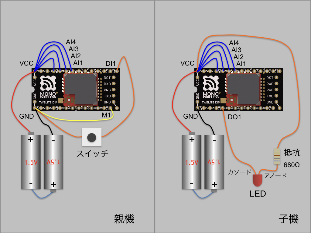
Example wiring (AI1-AI4 are optional)
Explanation of the Act
Declaration Section
Include
// use twelite mwx c++ template library
#include <TWELITE>
#include <NWK_SIMPLE>
#include <BRD_APPTWELITE>
#include <STG_STD>
<TWELITE> is included in all acts. Here, we also include the simple network <NWK_SIMPLE> and the board support <BRD_APPTWELITE>.
Additionally, <STG_STD> is included to add interactive mode.
Others
/*** Config part */
// application ID
const uint32_t DEFAULT_APP_ID = 0x1234abcd;
// channel
const uint8_t DEFAULT_CHANNEL = 13;
// option bits
uint32_t OPT_BITS = 0;
// logical id
uint8_t LID = 0;

/*** function prototype */
MWX_APIRET transmit();
void receive();

/*** application defs */
const char APP_FOURCHAR[] = "BAT1";

// sensor values
uint16_t au16AI[5];
uint8_t u8DI_BM;
- Common declarations for sample acts
- Prototype declarations for functions (transmit and receive) since some processing is separated into functions
- Variables to hold data in the application
setup()
void setup() {
	/*** SETUP section */
	// init vars
	for(auto&& x : au16AI) x = 0xFFFF;
	u8DI_BM = 0xFF;

	// load board and settings
	auto&& set = the_twelite.settings.use<STG_STD>();
	auto&& brd = the_twelite.board.use<BRD_APPTWELITE>();
	auto&& nwk = the_twelite.network.use<NWK_SIMPLE>();

	// settings: configure items
	set << SETTINGS::appname("BRD_APPTWELITE");
	set << SETTINGS::appid_default(DEFAULT_APP_ID); // set default appID
	set << SETTINGS::ch_default(DEFAULT_CHANNEL); // set default channel
	set.hide_items(E_STGSTD_SETID::OPT_DWORD2, E_STGSTD_SETID::OPT_DWORD3, E_STGSTD_SETID::OPT_DWORD4, E_STGSTD_SETID::ENC_KEY_STRING, E_STGSTD_SETID::ENC_MODE);
	set.reload(); // load from EEPROM.
	OPT_BITS = set.u32opt1(); // this value is not used in this example.
	LID = set.u8devid(); // logical ID

	// the twelite main class
	the_twelite
		<< set                      // apply settings (appid, ch, power)
		<< TWENET::rx_when_idle();  // open receive circuit (if not set, it can't listen packts from others)

	if (brd.get_M1()) { LID = 0; }

	// Register Network
	nwk << set // apply settings (LID and retry)
			;

	// if M1 pin is set, force parent device (LID=0)
	nwk << NWK_SIMPLE::logical_id(LID); // write logical id again.

	/*** BEGIN section */
	// start ADC capture
	Analogue.setup(true, ANALOGUE::KICK_BY_TIMER0); // setup analogue read (check every 16ms)
	Analogue.begin(pack_bits(
						BRD_APPTWELITE::PIN_AI1,
						BRD_APPTWELITE::PIN_AI2,
						BRD_APPTWELITE::PIN_AI3,
						BRD_APPTWELITE::PIN_AI4,
				   		PIN_ANALOGUE::VCC)); // _start continuous adc capture.

	// Timer setup
	Timer0.begin(32, true); // 32hz timer

	// start button check
	Buttons.setup(5); // init button manager with 5 history table.
	Buttons.begin(pack_bits(
						BRD_APPTWELITE::PIN_DI1,
						BRD_APPTWELITE::PIN_DI2,
						BRD_APPTWELITE::PIN_DI3,
						BRD_APPTWELITE::PIN_DI4),
					5, 		// history count
					4);  	// tick delta (change is detected by 5*4=20ms consequtive same values)


	the_twelite.begin(); // start twelite!

	/*** INIT message */
	Serial 	<< "--- BRD_APPTWELITE ---" << mwx::crlf;
	Serial	<< format("-- app:x%08x/ch:%d/lid:%d"
					, the_twelite.get_appid()
					, the_twelite.get_channel()
					, nwk.get_config().u8Lid
				)
			<< mwx::crlf;
	Serial 	<< format("-- pw:%d/retry:%d/opt:x%08x"
					, the_twelite.get_tx_power()
					, nwk.get_config().u8RetryDefault
					, OPT_BITS
			)
			<< mwx::crlf;
}
The general flow is initial setup of each part, followed by starting each part.
Registering Various Behavior Objects
	auto&& set = the_twelite.settings.use<STG_STD>();
	auto&& brd = the_twelite.board.use<BRD_APPTWELITE>();
	auto&& nwk = the_twelite.network.use<NWK_SIMPLE>();
Register behavior objects to determine the system’s behavior. This includes interactive mode settings management, board support, and wireless packet network description.
setup().Setting Up Interactive Mode
// インタラクティブモードの初期化
auto&& set = the_twelite.settings.use<STG_STD>();

set << SETTINGS::appname("BRD_APPTWELITE");
set << SETTINGS::appid_default(DEFAULT_APP_ID); // set default appID
set << SETTINGS::ch_default(DEFAULT_CHANNEL); // set default channel
set.hide_items(E_STGSTD_SETID::OPT_DWORD2, E_STGSTD_SETID::OPT_DWORD3, E_STGSTD_SETID::OPT_DWORD4, E_STGSTD_SETID::ENC_KEY_STRING, E_STGSTD_SETID::ENC_MODE);
set.reload(); // load from EEPROM.
OPT_BITS = set.u32opt1(); // this value is not used in this example.
LID = set.u8devid(); // logical ID;
Initializes interactive mode. First, the set object is obtained. Then, the following processing is performed:
- Sets the application name to
"BRD_APPTWELITE"(used in the menu) - Overwrites the default application ID and channel value
- Removes unnecessary items
- Reads the saved settings with
set.reload() - Copies the values of
OPT_BITSandLIDto variables
Below is an example screen. By entering + + + (three times, with intervals of 0.2 to 1 second), you can bring up the interactive mode screen.
[CONFIG/BRD_APPTWELITE:0/SID=8XXYYYYY]
a: (0x1234ABCD) Application ID [HEX:32bit]
i: (        13) Device ID [1-100,etc]
c: (        13) Channel [11-26]
x: (      0x03) RF Power/Retry [HEX:8bit]
o: (0x00000000) Option Bits [HEX:32bit]

 [ESC]:Back [!]:Reset System [M]:Extr Menu
the_twelite
This object acts as the core of TWENET.
auto&& brd = the_twelite.board.use<BRD_APPTWELITE>();
Register the board (in this act, <BRD_APPTWELITE> is registered). Specify the board name you want to register after use with <>.
The return value obtained by universal reference (auto&&) is a reference type board object. This object includes board-specific operations and definitions. Below, the board object is used to check the state of the M1 pin. If the M1 pin is LOW, LID is set to 0, i.e., the parent address.
if (brd.get_M1()) { LID = 0; }
Initial settings are required to operate the_twelite. Setting the application ID and wireless channel is essential.
	// the twelite main class
	the_twelite
		<< set
		<< TWENET::rx_when_idle();  // open receive circuit (if not set, it can't listen packts from others)
Use << to reflect settings in the_twelite.
setreflects some of the settings read from interactive mode (such as application ID and wireless channel). For details on reflected items, see the explanation of<STG_STD>.TWENET::rx_when_idle()specifies to open the receive circuit.
The << and >> operators are bit shift operators in C, but here they are used as stream insertion operators. In the MWX library, following the usage in the C++ standard library, they are used for settings, serial port I/O, and so on.
However, the following code cannot be used with the MWX library:
#include <iostream>
std::cout << "hello world" << std::endl;
次にネットワークを登録します。
auto&& nwk = the_twelite.network.use<NWK_SIMPLE>();
nwk << set;
nwk << NWK_SIMPLE::logical_id(LID);
The first line registers the network in the same way as the board, specifying <NWK_SIMPLE> in <>.
The second and third lines are settings for <NWK_SIMPLE>. First, the interactive mode settings are reflected. The reflected items are LID and the retry count. In this application, since LID may be set to 0 depending on the state of the M1 pin, LID is set again in the third line.
Analogue
This is a class object that handles ADC (Analog-to-Digital Converter).
Analogue.setup(true, ANALOGUE::KICK_BY_TIMER0);
Initialization is done with Analogue.setup(). The parameter true specifies to wait until the ADC circuit is stabilized. The second parameter specifies to synchronize the start of ADC with Timer0.
	Analogue.begin(pack_bits(
						BRD_APPTWELITE::PIN_AI1,
						BRD_APPTWELITE::PIN_AI2,
						BRD_APPTWELITE::PIN_AI3,
						BRD_APPTWELITE::PIN_AI4,
				   	PIN_ANALOGUE::VCC));
To start ADC, call Analogue.begin(). The parameter is a bitmap corresponding to the ADC target pins.
The pack_bits() function is used to specify the bitmap. It is a variadic function, and each argument specifies the bit position to set to 1. For example, pack_bits(1,3,5) returns the value 101010 in binary. Since this function is marked constexpr, if the parameters are all constants, it will be expanded as a constant.
BRD_APPTWELITE:: defines PIN_AI1..4 as parameters. These correspond to AI1..AI4 used in App_Twelite. The assignments are AI1=ADC1, AI2=DIO0, AI3=ADC2, AI4=DIO2. PIN_ANALOGUE:: defines a list of pins available for ADC.
Buttons
Detects changes in the value of DIO (digital input). Buttons reduces the effect of mechanical button chattering, and only considers a value change after the same value has been detected a certain number of times.
Buttons.setup(5);
Initialization is done with Buttons.setup(). The parameter 5 specifies the maximum number of detections required to confirm the value. Internally, this number is used to allocate memory.
Buttons.begin(pack_bits(
						BRD_APPTWELITE::PIN_DI1,
						BRD_APPTWELITE::PIN_DI2,
						BRD_APPTWELITE::PIN_DI3,
						BRD_APPTWELITE::PIN_DI4),
					5, 		// history count
					4);  	// tick delta
Start is done with Buttons.begin(). The first parameter is the DIO to detect. Specify PIN_DI1-4 (DI1-DI4) defined in BRD_APPTWELITE::. The second parameter is the number of detections required to confirm the state. The third parameter is the detection interval. Since 4 is specified, when the same value is detected five times in a row every 4ms, the state is confirmed as HIGH or LOW.
Buttons is performed in the event handler. The event handler is called in the application loop after an interrupt occurs, so it has more delay compared to the interrupt handler.Timer0
Timer0.begin(32, true); // 32hz timer
In App_Twelite, application control is based on a timer, so this act also operates timer interrupts and events in the same way. Of course, you can also use the system TickTimer, which operates every 1ms.
In the example above, the first parameter is the timer frequency, set to 32Hz. The second parameter enables the software interrupt when set to true.
After calling Timer0.begin(), the timer starts running.
the_tweliteの動作開始
the_twelite.begin(); // start twelite!
At the end of the setup() function, the_twelite.begin() is executed.
Serial
The Serial object can be used without initialization or start procedures.
	Serial 	<< "--- BRD_APPTWELITE ---" << mwx::crlf;
	Serial	<< format("-- app:x%08x/ch:%d/lid:%d"
					, the_twelite.get_appid()
					, the_twelite.get_channel()
					, nwk.get_config().u8Lid
				)
			<< mwx::crlf;
	Serial 	<< format("-- pw:%d/retry:%d/opt:x%08x"
					, the_twelite.get_tx_power()
					, nwk.get_config().u8RetryDefault
					, OPT_BITS
			)
			<< mwx::crlf;
In this sample, several system settings are displayed as a startup message. The Serial object can take a const char* string, int type (other integer types are not accepted), format() which behaves almost like printf(), and crlf for newlines, all using the << operator.
mwx:: namespace is sometimes omitted. In the above, it is written as mwx::crlf, but you can also write simply crlf. The mwx:: namespace is designed to allow partial omission.loop()
The loop function is called as a callback from the TWENET library’s main loop. The basic description here is to wait for the objects you use to become available and then process them. Below, we will explain the use of several objects used in this act.
The main loop of the TWENET library processes events such as received packets and interrupt information that have been stored in the FIFO queue in advance, and then calls loop(). After exiting loop(), the CPU enters DOZE mode and waits in low power consumption until a new interrupt occurs.
Therefore, code that assumes the CPU is always running will not work properly.
/*** loop procedure (called every event) */
void loop() {
	if (Buttons.available()) {
		uint32_t bp, bc;
		Buttons.read(bp, bc);

		u8DI_BM = uint8_t(collect_bits(bp,
							BRD_APPTWELITE::PIN_DI4,   // bit3
							BRD_APPTWELITE::PIN_DI3,   // bit2
							BRD_APPTWELITE::PIN_DI2,   // bit1
							BRD_APPTWELITE::PIN_DI1)); // bit0

		transmit();
	}

	if (Analogue.available()) {
		au16AI[0] = Analogue.read(PIN_ANALOGUE::VCC);
		au16AI[1] = Analogue.read_raw(BRD_APPTWELITE::PIN_AI1);
		au16AI[2] = Analogue.read_raw(BRD_APPTWELITE::PIN_AI2);
		au16AI[3] = Analogue.read_raw(BRD_APPTWELITE::PIN_AI3);
		au16AI[4] = Analogue.read_raw(BRD_APPTWELITE::PIN_AI4);
	}

	if (Timer0.available()) {
		static uint8_t u16ct;
		u16ct++;

		if (u8DI_BM != 0xFF && au16AI[0] != 0xFFFF) { // finished the first capture
			if ((u16ct % 32) == 0) { // every 32ticks of Timer0
				transmit();
			}
		}
	}
}
Buttons
When a change in DIO (Digital IO) input is detected, it becomes available, and you can read it using Buttons.read().
	if (Buttons.available()) {
		uint32_t bp, bc;
		Buttons.read(bp, bc);
The first parameter is the current bitmap of DIO HIGH/LOW states, with bit0 corresponding to DIO0, bit1 to DIO1, and so on. For example, for DIO12, you can check if it is HIGH or LOW by evaluating bp & (1UL << 12). Bits set to 1 indicate HIGH.
Next, the value is extracted from the bitmap and stored in u8DI_BM. Here, we use the collect_bits() function provided by the MWX library.
u8DI_BM = uint8_t(collect_bits(bp,
		BRD_APPTWELITE::PIN_DI4,   // bit3
		BRD_APPTWELITE::PIN_DI3,   // bit2
		BRD_APPTWELITE::PIN_DI2,   // bit1
		BRD_APPTWELITE::PIN_DI1)); // bit0

/* collect_bits performs the following:
u8DI_BM = 0;
if (bp & (1UL << BRD_APPTWELITE::PIN_DI1)) u8DI_BM |= 1;
if (bp & (1UL << BRD_APPTWELITE::PIN_DI2)) u8DI_BM |= 2;
if (bp & (1UL << BRD_APPTWELITE::PIN_DI3)) u8DI_BM |= 4;
if (bp & (1UL << BRD_APPTWELITE::PIN_DI4)) u8DI_BM |= 8;
*/
collect_bits() takes integer values representing bit positions, just like the pack_bits() mentioned earlier. It is a variadic function, so you can specify as many parameters as needed. In the above process, bit0 is DI1, bit1 is DI2, bit2 is DI3, and bit3 is DI4, and the result is stored in u8DI_BM.
In App_Twelite, a wireless transmission occurs when there is a change in DI1 to DI4, so the transmission process is triggered by Buttons.available(). The contents of the transmit() process are described later.
transmit();
Analogue
After the ADC (Analog-to-Digital Converter) conversion is completed, Analogue becomes available in the next loop(). Until the next ADC starts, you can read the data as the most recently obtained value.
// After ADC conversion is completed, Analogue becomes available in loop().
// Until the next ADC starts, you can read the most recent value.
To read ADC values, use the Analogue.read() or Analogue.read_raw() methods. read() returns the value converted to mV, while read_raw() returns the ADC value in the range 0..1023. Specify the ADC pin number as a parameter. ADC pin numbers are defined in PIN_ANALOGUE:: or BRD_APPTWELITE::, so use those.
Since ADC is executed periodically, depending on the timing, you may read a newer value than the one notified by available.
In this act, because processing is done at a relatively slow cycle of 32Hz, there is no problem if you process immediately after available is true. However, if the conversion cycle is short or if you have processing in loop() that takes a relatively long time, be careful.
Analogue allows you to specify a callback function that is called from within the interrupt handler after conversion is completed. For example, you can use this callback function to store values in a FIFO queue, and then read the values sequentially in the application loop for asynchronous processing.
Timer0
Timer0 operates at 32Hz. It becomes available in loop() immediately after a timer interrupt occurs. In other words, processing is done 32 times per second. Here, the transmission process is performed exactly once per second.
if (Timer0.available()) {
	static uint8_t u16ct;
	u16ct++;

	if (u8DI_BM != 0xFF && au16AI[0] != 0xFFFF) { // finished the first capture
		if ((u16ct % 32) == 0) { // every 32ticks of Timer0
			transmit();
		}
	}
}
AppTwelite sends periodically about once per second. When Timer0 becomes available, u16ct is incremented. Based on this counter value, after counting 32 times, transmit() is called to send a wireless packet.
The value checks for u8DI_BM and au16AI[] are to determine whether it is right after initialization. If the values for DI1..DI4 or AI1..AI4 have not yet been stored, nothing is done.
transmit()
This function issues a request to TWENET to transmit a wireless packet. When this function returns, the wireless packet has not yet been processed. Actual transmission will be completed several milliseconds later, depending on the transmission parameters. Here, typical transmission request methods are explained.
MWX_APIRET transmit() {
	if (auto&& pkt = the_twelite.network.use<NWK_SIMPLE>().prepare_tx_packet()) {
	  auto&& set = the_twelite.settings.use<STG_STD>();
		if (!set.is_screen_opened()) {
			Serial << "..DI=" << format("%04b ", u8DI_BM);
			Serial << format("ADC=%04d/%04d/%04d/%04d ", au16AI[1], au16AI[2], au16AI[3], au16AI[4]);
			Serial << "Vcc=" << format("%04d ", au16AI[0]);
			Serial << " --> transmit" << mwx::crlf;
		}

		// set tx packet behavior
		pkt << tx_addr(u8devid == 0 ? 0xFE : 0x00)  // 0..0xFF (LID 0:parent, FE:child w/ no id, FF:LID broad cast), 0x8XXXXXXX (long address)
			<< tx_retry(0x1) // set retry (0x1 send two times in total)
			<< tx_packet_delay(0,50,10); // send packet w/ delay (send first packet with randomized delay from 100 to 200ms, repeat every 20ms)

		// prepare packet payload
		pack_bytes(pkt.get_payload() // set payload data objects.
			, make_pair(APP_FOURCHAR, 4) // string should be paired with length explicitly.
			, uint8_t(u8DI_BM)
		);

		for (auto&& x : au16AI) {
			pack_bytes(pkt.get_payload(), uint16_t(x)); // adc values
		}

		// do transmit
		return pkt.transmit();
	}
	return MWX_APIRET(false, 0);
}
Function Prototype
MWX_APIRET transmit()
MWX_APIRET is a class that handles return values with a uint32_t data member. The MSB (bit31) indicates success or failure, and the other bits are used as the return value.
Obtaining Network and Packet Objects
if (auto&& pkt = the_twelite.network.use<NWK_SIMPLE>().prepare_tx_packet()) {
Obtain the network object with the_twelite.network.use<NWK_SIMPLE>(). Then use that object to obtain the pkt object with .prepare_tx_packet().
Here, it is declared within the condition of the if statement. The declared pkt object is valid until the end of the if block. The pkt object responds as a bool type: it is true if the TWENET transmission request queue has space to accept the request, and false if there is no space.
Suppressing Output While Interactive Mode Screen Is Open
auto&& set = the_twelite.settings.use<STG_STD>();
if (!set.is_screen_opened()) {
    // Not in interactive mode screen!
}
Output is suppressed when the interactive mode screen is displayed.
Packet Transmission Settings
pkt << tx_addr(u8devid == 0 ? 0xFE : 0x00)  // 0..0xFF (LID 0:parent, FE:child w/ no id, FF:LID broad cast), 0x8XXXXXXX (long address)
		<< tx_retry(0x1) // set retry (0x3 send four times in total)
		<< tx_packet_delay(0,50,10); // send packet w/ delay (send first packet with randomized delay from 100 to 200ms, repeat every 20ms)
Packet settings are configured using the << operator, similar to the initialization settings of the_twelite.
tx_addr(): Specifies the destination address. If0x00, it means sending from a child to the parent; if0xFE, it means sending from a parent as a broadcast to any child.tx_retry(): Specifies the number of retransmissions. For example, 1 means retransmit once, so two packets in total are sent. Even in good conditions, sending a wireless packet only once can result in a few percent failure rate.tx_packet_delay(): Sets the transmission delay. The first parameter is the minimum waiting time before transmission starts, the second is the maximum waiting time. In this case, after issuing the transmission request, the transmission starts at a random time between 0 and 50 ms. The third parameter is the retransmission interval. It means retransmitting every 10 ms after the first packet is sent.
Packet Data Payload
Payload means “cargo,” but in wireless packets it often refers to the “main data you want to send.” Wireless packets also contain auxiliary information such as address information, in addition to the main data.
To ensure correct transmission and reception, pay attention to the order of data in the payload. Here, the following data order is used. Construct the data payload according to this order.
# Index of the first byte: Data type : Byte size : Content

00: uint8_t[4] : 4 : 4-character identifier
04: uint8_t    : 1 : Bitmap of DI1..4
06: uint16_t   : 2 : Vcc voltage value
08: uint16_t   : 2 : AI1 ADC value (0..1023)
10: uint16_t   : 2 : AI2 ADC value (0..1023)
12: uint16_t   : 2 : AI3 ADC value (0..1023)
14: uint16_t   : 2 : AI4 ADC value (0..1023)
Up to 90 bytes can be stored in the data payload (in reality, a few more bytes can fit).
In IEEE802.15.4 wireless packets, every byte is valuable. It is recommended to use them as sparingly as possible. There is a limit to the amount of data that can be sent in one packet. If you split the data into multiple packets, you must consider the cost and risk of packet loss. Also, sending one extra byte consumes energy equivalent to about 16μs times the transmission current, which greatly affects battery-powered applications.
The above example makes some compromises for explanation purposes. If you want to save data, the identifier at 00: should be a simple one-byte value, and the VCC voltage can be rounded to 8 bits. Also, the values for AI1..AI4 are 10 bits each, so while the total is 40 bits (5 bytes), 6 bytes are actually used.
Let’s actually construct the data structure of the payload described above. The data payload can be referenced as a simplbuf<uint8_t> container via pkt.get_payload(). Build the data in this container according to the above specifications.
auto&& payl = pkt.get_payload();
payl.reserve(16); // resize to 16 bytes
payl[00] = APP_FOURCHAR[0];
payl[01] = APP_FOURCHAR[1];
...
payl[08] = (au16AI[0] & 0xFF00) >> 8; //Vcc
payl[09] = (au16AI[0] & 0xFF);
...
payl[14] = (au16AI[4] & 0xFF00) >> 8; // AI4
payl[15] = (au16AI[4] & 0xFF);
You can write it as shown above, but the MWX library provides a helper function pack_bytes() for constructing the data payload.
// prepare packet payload
pack_bytes(pkt.get_payload() // set payload data objects.
	, make_pair(APP_FOURCHAR, 4) // string should be paired with length explicitly.
	, uint8_t(u8DI_BM)
);

for (auto&& x : au16AI) {
	pack_bytes(pkt.get_payload(), uint16_t(x)); // adc values
}
The first parameter of pack_bytes() specifies the container, in this case pkt.get_payload().
The following parameters are variadic arguments, and you specify as many values of supported types as needed. Internally, pack_bytes() calls the .push_back() method to append the specified values to the end.
On the third line, make_pair() is a standard library function that generates a std::pair. This is specified to avoid confusion with string types (specifically, whether or not to include null characters in the payload). The first parameter of make_pair() should be a string type (such as char*, uint8_t*, or uint8_t[]). The second parameter is the number of bytes to be stored in the payload.
On the fourth line, the bitmap of DI1..DI4 is written as a uint8_t.
On lines 7-9, the values of the au16AI array are written sequentially. These values are of uint16_t type (2 bytes), and are written in big-endian order.
The for statement on line 7 is a C++ range-based for loop. This syntax can be used for arrays of known size and container classes that support access via begin() and end() iterators. The type of au16AI can also be determined at compile time, so type specification is omitted using auto&& (universal reference).
If rewritten as a normal for loop, it would look like the following:
for(int i = 0; i < sizeof(au16AI)/sizeof(uint16_t)); i++) {
  pack_bytes(pkt.get_payload(), au16AI[i]);
}
With this, preparation of the packet is complete. Now, simply issue the transmission request.
return pkt.transmit();
To send the packet, use the pkt.transmit() method of the pkt object. The return value is of type MWX_APIRET, but it is not used in this act.
on_rx_packet()
When a wireless packet is received, the reception event on_rx_packet() is called.
the_twelite.receiver, received packets were temporarily stored in an internal queue (up to two packets) before processing, but with on_rx_packet(), it is called directly from the callback of the TWENET library, making it less likely for packets to be missed. However, if processing inside the loop() statement is blocked for a long time, packets may still be missed for the same reason.Here, the values of DI1..DI4 and AI1..AI4 received from the other party are set to the local DO1..DO4 and PWM1..PWM4.
void on_rx_packet(packet_rx& rx, bool_t &handled) {
	auto&& set = the_twelite.settings.use<STG_STD>();

	Serial << format("..receive(%08x/%d) : ", rx.get_addr_src_long(), rx.get_addr_src_lid());

  // expand the packet payload
	char fourchars[5]{};
	auto&& np = expand_bytes(rx.get_payload().begin(), rx.get_payload().end()
		, make_pair((uint8_t*)fourchars, 4)  // 4bytes of msg
    );

	// check header
	if (strncmp(APP_FOURCHAR, fourchars, 4)) { return; }

	// read rest of payload
	uint8_t u8DI_BM_remote = 0xff;
	uint16_t au16AI_remote[5];
	expand_bytes(np, rx.get_payload().end()
		, u8DI_BM_remote
		, au16AI_remote[0]
		, au16AI_remote[1]
		, au16AI_remote[2]
		, au16AI_remote[3]
		, au16AI_remote[4]
	);

	Serial << format("DI:%04b", u8DI_BM_remote & 0x0F);
	for (auto&& x : au16AI_remote) {
		Serial << format("/%04d", x);
	}
	Serial << mwx::crlf;

	// set local DO
	digitalWrite(BRD_APPTWELITE::PIN_DO1, (u8DI_BM_remote & 1) ? HIGH : LOW);
	digitalWrite(BRD_APPTWELITE::PIN_DO2, (u8DI_BM_remote & 2) ? HIGH : LOW);
	digitalWrite(BRD_APPTWELITE::PIN_DO3, (u8DI_BM_remote & 4) ? HIGH : LOW);
	digitalWrite(BRD_APPTWELITE::PIN_DO4, (u8DI_BM_remote & 8) ? HIGH : LOW);

	// set local PWM : duty is set 0..1024, so 1023 is set 1024.
	Timer1.change_duty(au16AI_remote[1] == 1023 ? 1024 : au16AI_remote[1]);
	Timer2.change_duty(au16AI_remote[2] == 1023 ? 1024 : au16AI_remote[2]);
	Timer3.change_duty(au16AI_remote[3] == 1023 ? 1024 : au16AI_remote[3]);
	Timer4.change_duty(au16AI_remote[4] == 1023 ? 1024 : au16AI_remote[4]);
}
Function Prototype
void on_rx_packet(packet_rx& rx, bool_t &handled)
The received packet data rx is passed as a parameter. From rx, you can access the address information and data payload of the wireless packet. The handled parameter is not typically used.
Displaying the Source Address
if (!set.is_screen_opened()) {
   Serial << format("..receive(%08x/%d) : ",
      rx.get_addr_src_long(), rx.get_addr_src_lid());
}
The received packet data refers to information such as the source address (32-bit long address and 8-bit logical address). Output is suppressed when the interactive mode screen is displayed.
<NWK_SIMPLE>, both an 8-bit logical ID and a 32-bit long address are always exchanged. When specifying a destination, either the long address or logical address is used. Both addresses are included upon reception.Packet Identification
The MWX library provides the function expand_bytes(), which is the counterpart to pack_bytes() used in transmit().
char fourchars[5]{};
auto&& np = expand_bytes(rx.get_payload().begin(), rx.get_payload().end()
	, make_pair((uint8_t*)fourchars, 4)  // 4bytes of msg
  );
The first line declares a char array to store the data. The size is 5 bytes in order to include a null terminator for convenience in character output. The trailing {} is an initializer; although you could simply set the fifth byte to zero, here the entire array is initialized to zero by default.
On the second line, a 4-byte string is extracted using expand_bytes(). The reason for not specifying a container type as a parameter is to keep track of the read position for subsequent extraction. The first parameter specifies the beginning iterator (a uint8_t* pointer) of the container, obtained with the .begin() method. The second parameter is the iterator just past the end of the container, obtained with the .end() method. This ensures that reads do not exceed the end of the container.
For the third argument, specify the variable to read into, again using make_pair() to specify the string array and its size as a pair.
expand_bytes() for validation.
The return value of expand_bytes() is a uint8_t*; if you attempt to read past the end, it returns nullptr.If the identifier in the extracted 4-byte string differs from the one specified in this act, the packet is ignored.
if (strncmp(APP_FOURCHAR, fourchars, 4)) { return; }
<NWK_SIMPLE>. Unless another application not using the simple network defines the exact same packet structure (which is extremely rare), mixed reception of packets should not occur.Retrieving the Data Payload
Store the values of DI1..DI4 and AI1..AI4 into separate variables.
	// read rest of payload
	uint8_t u8DI_BM_remote = 0xff;
	uint16_t au16AI_remote[5];
	expand_bytes(np, rx.get_payload().end()
		, u8DI_BM_remote
		, au16AI_remote[0]
		, au16AI_remote[1]
		, au16AI_remote[2]
		, au16AI_remote[3]
		, au16AI_remote[4]
	);
Here, the return value np from the earlier expand_bytes() call is used as the first parameter, indicating that reading should start from immediately after the 4-byte identifier just extracted. The second parameter is handled in the same way.
The third and subsequent parameters specify variables whose types and order correspond to those in the payload, matching the data structure on the sender side. When this process is complete, the extracted values from the payload are stored in the specified variables.
Displaying the Retrieved Data
For confirmation, the data is output to the serial port. Output is suppressed when the interactive mode screen is displayed.
auto&& set = the_twelite.settings.use<STG_STD>();
...
Serial << format("DI:%04b", u8DI_BM_remote & 0x0F);
for (auto&& x : au16AI_remote) {
	Serial << format("/%04d", x);
}
Serial << mwx::crlf;
The format() function is used for numeric formatting. It is a helper class that enables the use of printf-style syntax for the >> operator, but it is limited to four arguments (there is no such limit with Serial.printfmt()).
On the third line, "DI:%04b" displays the bitmap of DI1..DI4 in four digits, e.g., “DI:0010”.
On the fifth line, "/%04d" outputs the values of Vcc and AI1..AI4 sequentially as integers, such as “/3280/0010/0512/1023/1023”.
On the seventh line, mwx::crlf outputs a newline character.
Outputting the Signals
Once the required data is extracted, update the values of DO1..DO4 and PWM1..PWM4 on the board.
// set local DO
digitalWrite(BRD_APPTWELITE::PIN_DO1, (u8DI_BM_remote & 1) ? HIGH : LOW);
digitalWrite(BRD_APPTWELITE::PIN_DO2, (u8DI_BM_remote & 2) ? HIGH : LOW);
digitalWrite(BRD_APPTWELITE::PIN_DO3, (u8DI_BM_remote & 4) ? HIGH : LOW);
digitalWrite(BRD_APPTWELITE::PIN_DO4, (u8DI_BM_remote & 8) ? HIGH : LOW);

// set local PWM : duty is set 0..1024, so 1023 is set 1024.
Timer1.change_duty(au16AI_remote[1] == 1023 ? 1024 : au16AI_remote[1]);
Timer2.change_duty(au16AI_remote[2] == 1023 ? 1024 : au16AI_remote[2]);
Timer3.change_duty(au16AI_remote[3] == 1023 ? 1024 : au16AI_remote[3]);
Timer4.change_duty(au16AI_remote[4] == 1023 ? 1024 : au16AI_remote[4]);
digitalWrite() changes the value of a digital output. The first parameter is the pin number; the second specifies either HIGH (VCC level) or LOW (GND level).
Timer?.change_duty() changes the PWM output duty cycle. Specify the duty as a value between 0..1024. Note that the maximum value is not 1023. Since division operations within the library are computationally expensive, a power of two (1024) is used as the maximum value. Setting the parameter to 0 outputs GND level; setting it to 1024 outputs VCC level.