BRD_I2C_TEMPHUMID
This sample uses the I2C sensor device mounted on our AMBIENT SENSE PAL or TWELITE ARIA BLUE / RED. However, by rewriting the I2C command send/receive section, you can use other general-purpose I2C sensor devices (shown as Generic I2C Sensor Module in the diagram). In that case, please wire as shown below.
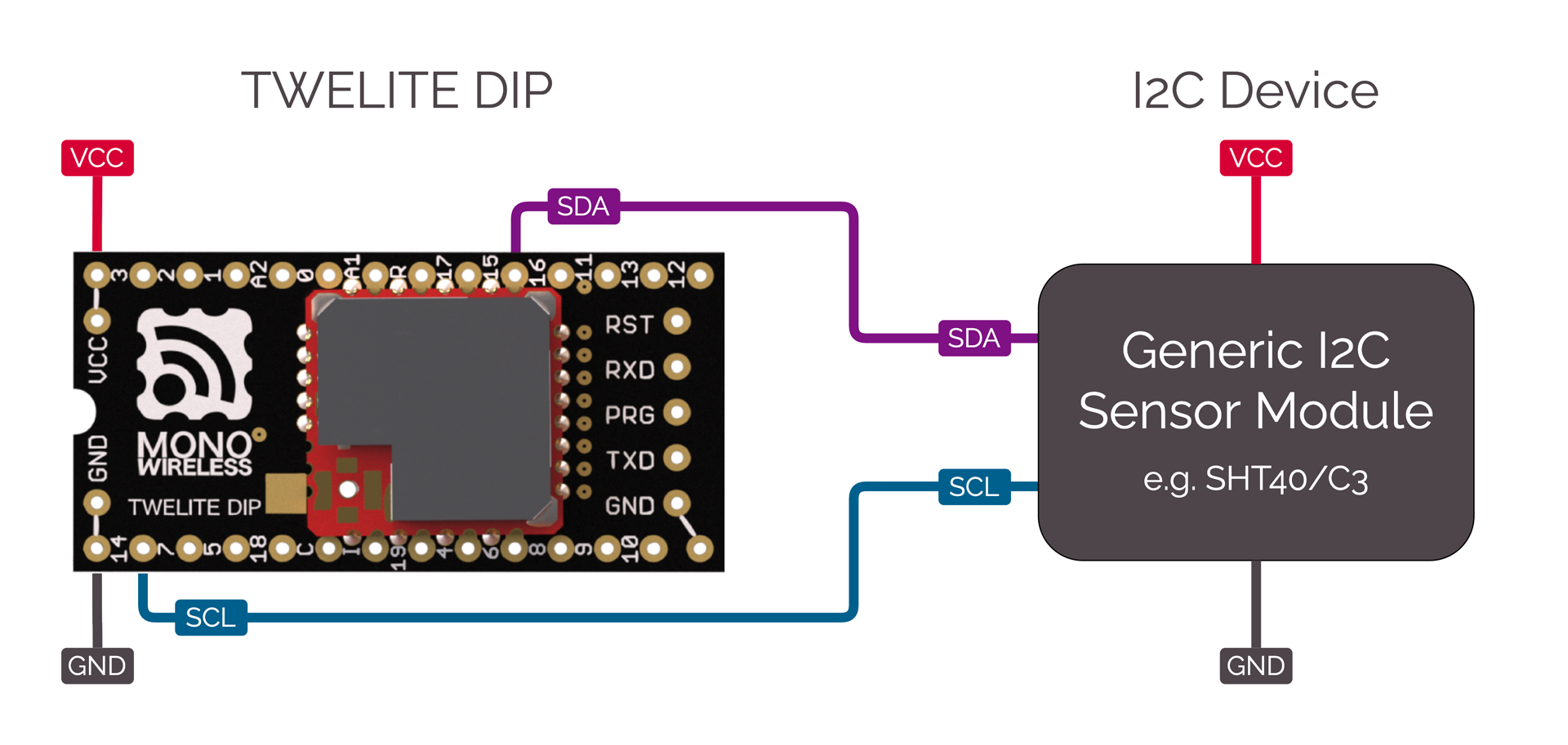
Connection of a generic I2C device
This act includes the following:
- Sending and receiving wireless packets
- Configuration via interactive mode -
<STG_STD> - State transition control via state machine -
<SM_SIMPLE>
Act Features
- Sends and receives commands to/from the I2C device.
- Uses sleep functionality to operate on coin cell batteries.
How to Use the Act
Required TWELITE
| Role | Example |
|---|---|
| Parent | MONOSTICK BLUE / REDRun act Parent_MONOSTICK. |
| Child | - BLUE / RED PAL + AMBIENT SENSE PAL- TWELITE ARIA BLUE / RED |
Explanation of the Act
Include
#include <TWELITE>
#include <NWK_SIMPLE>// ネットワークサポート
#include <STG_STD>   // インタラクティブモード
#include <SM_SIMPLE> // 簡易ステートマシン
<NWK_SIMPLE> is required for wireless communication, <STG_STD> adds interactive mode, and <SM_SIMPLE> is included to simplify the application loop description.
Sensor Driver
In this example, there are two types of code: SHTC3 (TWELITE AMB PAL) and SHT40 (TWELITE ARIA), which are switched using #ifdef (please #define either USE_SHTC3 or USE_SHT40). For portability, both types are defined with the same function interface. Since both sensors are from the same manufacturer and series, the code is similar.
/*** sensor select, define either of USE_SHTC3 or USE_SHT40  */
// use SHTC3 (TWELITE PAL)
#define USE_SHTC3
// use SHT40 (TWELITE ARIA)
#undef USE_SHT40
以下では SHTC3 の例を示します。
#if defined(USE_SHTC3)
// for SHTC3
struct SHTC3 {
	uint8_t I2C_ADDR;
	uint8_t CONV_TIME;

    bool setup() { ... }
	bool begin() { ... }
	int get_convtime() { return CONV_TIME; }
	bool read(int16_t &i16Temp, int16_t &i16Humd) { ... }
} sensor_device;
Here, the I2C sensor-related procedures are organized into the SHTC3 struct (class) for clarity. This struct has member variables for the I2C address I2C_ADDR and the wait time for acquiring values CONV_TIME, and is declared with the instance name sensor_device.
This struct (class) has the following member functions:
| Function Name | Description |
|---|---|
setup() | Initializes the struct. |
begin() | Starts acquiring sensor values.After starting, you must wait a certain period for valid sensor values. |
get_convtime() | Returns the sensor value acquisition wait time. |
read(int&, int&) | Acquires the sensor values. |
setup() instead of the constructor.Let’s look at each process step by step.
setup()
bool setup() {
	// here, initialize some member vars instead of constructor.
	I2C_ADDR = 0x70;
	CONV_TIME = 10; // wait time [ms]
	return true;
}
Set the I2C address and the sensor value acquisition wait time (10ms above) to the member variables.
These values are basically fixed, so you do not need to set them as variables. Valid examples for treating them as variables include cases where you want to manage conversion time for higher-precision sensor operation depending on settings, or select a sub-address for I2C depending on configuration.
begin()
bool begin() {
	// send start trigger command
	if (auto&& wrt = Wire.get_writer(I2C_ADDR)) {
		wrt << 0x60; // SHTC3_TRIG_H
		wrt << 0x9C; // SHTC3_TRIG_L
	} else {
		return false;
	}
	return true;
}
Writes a command to operate the sensor.
The MWX library provides two different ways to read/write the I2C bus using the Wire class object; this is the helper function method.
In the if statement, Wire.get_writer(I2C_ADDR) opens the I2C device at address I2C_ADDR and generates a read/write object. The read/write object wrt returns false if the device fails to open (evaluated as (bool) in the if statement). If true, it means it opened successfully and the processing inside the if block is performed.
Here, wrt << 0x60; writes a byte to the I2C device using the stream operator <<. This operator is basically for writing a single byte of type uint8_t.
get_convtime()
int get_convtime() {
	return CONV_TIME;
}
This function returns the value of CONV_TIME.
read()
bool read(int16_t &i16Temp, int16_t &i16Humd) {
	// read result
	uint16_t u16temp, u16humd;
	uint8_t u8temp_csum, u8humd_csum;
	if (auto&& rdr = Wire.get_reader(I2C_ADDR, 6)) {
		rdr >> u16temp;      // read two bytes (MSB first)
		rdr >> u8temp_csum;  // check sum (crc8)
		rdr >> u16humd;      // read two bytes (MSB first)
		rdr >> u8humd_csum;  // check sum (crc8)
	} else {
		return false;
	}

	// check CRC and save the values
	if (   (CRC8_u8CalcU16(u16temp, 0xff) == u8temp_csum)
		&& (CRC8_u8CalcU16(u16humd, 0xff) == u8humd_csum))
	{
		i16Temp = (int16_t)(-4500 + ((17500 * int32_t(u16temp)) >> 16));
		i16Humd = (int16_t)((int32_t(u16humd) * 10000) >> 16);
	} else {
		return false;
	}

	return true;
}
Reads the sensor data.
For SHTC3, after starting sensor readout with begin(), you wait a few ms and then read the sensor values. The arrangement of sensor values is as follows:
| Byte | Description |
|---|---|
| 0 | Temperature sensor value (upper byte) |
| 1 | Temperature sensor value (lower byte) |
| 2 | CRC8 value for bytes 0,1 |
| 3 | Humidity sensor value (upper byte) |
| 4 | Humidity sensor value (lower byte) |
| 5 | CRC8 value for bytes 3,4 |
0x609C command written in begin() above, the temperature data arrives first.In begin(), data was written, but here, data is read. To read data, similarly generate a helper object rdr using Wire.get_reader(). If there are no errors, rdr returns true in the if block. The second parameter 6 in get_reader(I2C_ADDR, 6) is the number of bytes to read. When this number of bytes has been read, the I2C bus readout process ends. (Depending on the device, you may omit this, but usually you should provide the appropriate value.)
Reading is done with the stream operator >>. There are other ways to read; for details, see helper functions. When using the stream operator, you input values into pre-declared variables of type uint8_t, uint16_t, or uint32_t. rdr >> u16temp reads two bytes from the I2C bus into a uint16_t variable in big-endian format (first byte is upper byte).
Finally, i16Temp and i16Humd are calculated and stored as 100 times the temperature [°C] and 100 times the humidity [%], respectively. For the calculation formulas, refer to the I2C device datasheet.
setup()
The setup() function is called only once when TWELITE starts. This function performs various initializations.
void setup() {
	/*** SETUP section */
	...
}
State Machine SM_SIMPLE Initialization
// application state defs
enum class STATE : uint8_t {
	INTERACTIVE = 255,
	INIT = 0,
	SENSOR,
	TX,
	TX_WAIT_COMP,
	GO_SLEEP
};

// simple state machine.
SM_SIMPLE<STATE> step;

void setup() {
	...
	/// init vars or objects
	step.setup(); // initialize state machine
	...
}
The state machine is used to simplify the description in the loop() statement, which is called repeatedly. Of course, you do not have to use SM_SIMPLE to describe your application.
SM_SIMPLE is implemented in very short code, and allows easy management of state transitions, timeouts, and flags. The states are defined in advance as an enumeration. In the example above, it’s enum class STATE. The state machine instance is declared as SM_SIMPLE<STATE> step using the defined STATE enum as a parameter.
Registering Behaviors
void setup() {
	...
	/// load board and settings objects
	auto&& set = the_twelite.settings.use<STG_STD>(); // load save/load settings(interactive mode) support
	auto&& nwk = the_twelite.network.use<NWK_SIMPLE>(); // load network support
	...
}
Behavior is a set of functions used in the program. It describes what to do when various events occur.
Here, two behaviors are used: the interactive mode screen <STG_STD> and the simple relay network <NWK_SIMPLE>.
Setting up Interactive Mode STG_STD
	...
	/// configure settings
	// configure settings
	set << SETTINGS::appname(FOURCHARS);
	set << SETTINGS::appid_default(DEFAULT_APP_ID); // set default appID
	set << SETTINGS::ch_default(DEFAULT_CHANNEL); // set default channel
	set.hide_items(E_STGSTD_SETID::OPT_DWORD2, E_STGSTD_SETID::OPT_DWORD3, E_STGSTD_SETID::OPT_DWORD4, 	E_STGSTD_SETID::ENC_KEY_STRING, E_STGSTD_SETID::ENC_MODE);
Initial settings are made for STG_STD so that the interactive mode setting items match the application being described.
SETTINGS::appname: Specifies the application name (string). Displayed on the first line in the interactive mode screen. Keep the string short as there is little space on the screen.SETTINGS::appid_default: Default application ID. Use this if you want to set a custom default application ID for your own application.SETTINGS::ch_default: Default channel. Use this if you want to set a custom default channel for your own application.
Next, set.hide_items() removes unnecessary setting items from the default interactive mode screen. If you don’t mind displaying everything, you don’t need this call.
	// if SET(DIO12)=LOW is detected, start with intaractive mode.
	if (digitalRead(PIN_DIGITAL::DIO12) == PIN_STATE::LOW) {
		set << SETTINGS::open_at_start();
		step.next(STATE::INTERACTIVE);
		return;
	}
If the DIO12 pin is LOW (GND level) when power is applied or reset, this code starts in interactive mode. It reads the pin state with digitalRead() and applies SETTINGS::open_at_start().
To prevent normal application processing from running during interactive mode, the state machine is set to STATE::INTERACTIVE. In this state, no input or other processing is performed, and it remains in the same state.
	// load values
	set.reload(); // load from EEPROM.
	OPT_BITS = set.u32opt1(); // this value is not used in this example.

	// LID is configured DIP or settings.
	LID = set.u8devid(); // 2nd is setting.
	if (LID == 0) LID = 0xFE; // if still 0, set 0xFE (anonymous child)
Finally, the data for interactive mode is loaded. Calling set.reload() reads data written to EEPROM. If no settings were made and EEPROM has no information, default values are used.
Here, the option bits (set.u32opt1()) and 8-bit logical ID (set.u8devid()) are read. If LID is 0, it is usually operated as a parent, so if this value is recorded, it is set to 0xFE (child with no assigned ID).
	/// configure system basics
	the_twelite << set; // apply settings (from interactive mode)
	nwk << set; // apply settings (from interactive mode)
	nwk << NWK_SIMPLE::logical_id(LID); // set LID again (LID can also be configured by DIP-SW.)
	...
Finally, the configuration information (part of it) is applied to the_twelite and nwk. Essential information for wireless communication, such as application ID and channel, is reflected. There is no explicit code above for reading these settings, but with set.reload(), default values are used if there are no settings, and configured values are loaded if present.
Peripheral Initialization
	/*** BEGIN section */
	Wire.begin(); // start two wire serial bus.
This initializes the I2C sensor settings.
Start MWX
	// let the TWELITE begin!
	the_twelite.begin();

	/*** INIT message */
	Serial << "--- TEMP&HUMID:" << FOURCHARS << " ---" << mwx::crlf;
	Serial	<< format("-- app:x%08x/ch:%d/lid:%d"
					, the_twelite.get_appid()
					, the_twelite.get_channel()
					, nwk.get_config().u8Lid
				)
			<< mwx::crlf;
	Serial 	<< format("-- pw:%d/retry:%d/opt:x%08x"
					, the_twelite.get_tx_power()
					, nwk.get_config().u8RetryDefault
					, OPT_BITS
			)
			<< mwx::crlf;
the_twelite.begin() declares the completion of MWX library initialization. If you do not perform this process, the MWX library will not operate properly.
Startup messages, etc. are also displayed here.
loop()
void loop() {
	do {
		switch (step.state()) {
		 // 各状態の振る舞い
		case STATE::INIT:
		...
		break;
		...
		}
	while(step.b_more_loop());
}
The loop() uses the SM_SIMPLE state machine step for control. This is to concisely represent the flow from wakeup from sleep, sensor value acquisition, wireless packet transmission, waiting for transmission completion, and sleeping.
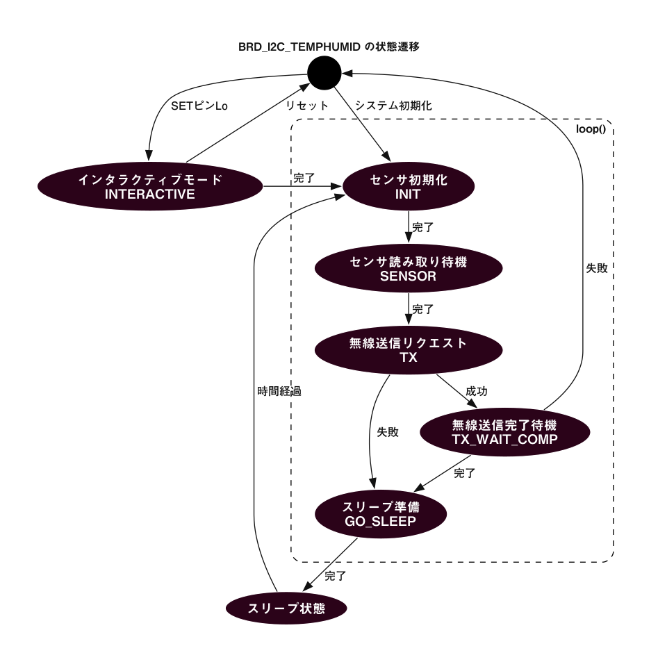
State machine diagram
The above do while control structure is described here. The state is determined by step.state(). The while condition is step.b_more_loop(). This is because, when transitioning from one state to another, you may want to process continuously without exiting loop(). In other words, when transitioning to another state and exiting the switch block, the next state’s case block is called. Be careful with this behavior.
case STATE::INTERACTIVE:
Because it is undesirable for the main loop to run during interactive mode, it is fixed to this state.
case STATE::INIT:
// start sensor capture
sensor_device.begin();
step.set_timeout(sensor_device.get_convtime()); // set timeout
step.next(STATE::SENSOR);
Starts sensor data acquisition. set_timeout() is used to wait for the sensor acquisition time.
For sensors with a very long wait time, you could describe a process here to sleep temporarily, which would extend battery life, but this is omitted in this example for simplicity. If needed, refer to the example for sleep waiting.
case STATE::SENSOR:
if (step.is_timeout()) {
	// the sensor data should be ready (wait some)
	sensor_device.read(sensor.i16temp, sensor.i16humid);

	Serial << "..finish sensor capture." << mwx::crlf
		<< "     : temp=" << div100(sensor.i16temp) << 'C' << mwx::crlf
		<< "       humd=" << div100(sensor.i16humid) << '%' << mwx::crlf
		;
	Serial.flush();

	step.next(STATE::TX);
}
Acquire sensor values using sensor_device.read() and store them in the sensor struct.
First, a timeout check is performed using step.is_timeout(). The starting point for the timeout is the earlier step.set_timeout(). If not timed out, the if block is not executed, and loop() exits as is. Until the next hardware event (usually an interrupt from the TickTimer system timer every 1ms), the TWELITE microcontroller is in low-power DOZE mode with the CPU waiting.
As a wireless sensor, it is not necessary to output the results to the serial port of the sensor-side TWELITE, but for easy operation confirmation, the acquired values are displayed on the serial port. Here, Serial.flush() is used to wait for output, assuming that serial port output may not finish before TWELITE goes to sleep. This process can also cause battery drain, so you may want to avoid using Serial.flush() or not output to the serial port.
The div100() function used here performs division by 100 at low cost. Since TWELITE has no division circuit, it is recommended to avoid division processing as much as possible.
case STATE::TX:
step.next(STATE::GO_SLEEP); // set default next state (for error handling.)

// get new packet instance.
if (auto&& pkt = the_twelite.network.use<NWK_SIMPLE>().prepare_tx_packet()) {
	...
}
Describes the communication procedure. No waiting is done in this state; after executing the process, it promptly transitions to the next state. The preemptive step.next(STATE::GO_SLEEP) is written to avoid having to write the same code in every place where errors are detected, as errors may be detected in multiple locations.
if (auto&& pkt = the_twelite.network.use<NWK_SIMPLE>().prepare_tx_packet()) creates a transmit packet object, and if successful, the if block is executed.
// set tx packet behavior
pkt << tx_addr(0x00)  // 0..0xFF (LID 0:parent, FE:child w/ no id, FF:LID broad cast), 0x8XXXXXXX (long address)
	<< tx_retry(0x1) // set retry (0x1 send two times in total)
	<< tx_packet_delay(0, 0, 2); // send packet w/ delay
First, transmission settings are made. The destination tx_addr(0x00) is set to parent 0x00, the number of retries tx_retry(0x1) is set to 1, and the packet delay setting tx_packet_delay(0, 0, 2) sets the initial delay to 0 and the retransmission interval to 2ms.
pack_bytes(pkt.get_payload()
	, make_pair(FOURCHARS, 4)
	, uint16_t(sensor.i16temp)
	, uint16_t(sensor.i16humid)
	);
Stores the identifier FOURCHARS and sensor data in the payload section of the packet. The obtained temperature value is int16_t, but since the transmit packet data structure stores it unsigned, it is cast to uint16_t.
// do transmit
MWX_APIRET ret = pkt.transmit();

if (ret) {
	step.clear_flag(); // waiting for flag is set.
	step.set_timeout(100); // set timeout
	step.next(STATE::TX_WAIT_COMP);}
Calling pkt.transmit() requests transmission. At this point, transmission does not start yet; the request is just placed in the internal queue. The MWX library processes the request at the appropriate timing.
If the transmit request succeeds, ret is true. To judge completion, the flag is initialized with step.clear_flag(), a timeout is set with step.set_timeout(100) to handle unexpected errors such as transmission failure, and the next state is set to STATE::TX_WAIT_COMP (overwriting the previously set STATE::GO_SLEEP).
case STATE::TX_WAIT_COMP:
Here, waits for transmission completion. Performs timeout judgment (in case of error) or transmission completion event judgment.
if (step.is_timeout()) { // maybe fatal error.
	the_twelite.reset_system();
}
if (step.is_flag_ready()) { // when tx is performed
	Serial << "..transmit complete." << mwx::crlf;
	Serial.flush();
	step.next(STATE::GO_SLEEP);
}
STATE::GO_SLEEP:
Processes sleepNow(). Calling this function puts TWELITE into sleep state.
on_tx_comp()
void on_tx_comp(mwx::packet_ev_tx& ev, bool_t &b_handled) {
	step.set_flag(ev.bStatus);
}
This is a system event called when transmission is complete. Here, .set_flag() is called to set the flag of step.
sleepNow()
void sleepNow() {
	step.on_sleep(false); // reset state machine.

	// randomize sleep duration.
	uint32_t u32ct = 1750 + random(0,500);

	// output message
	Serial << "..sleeping " << int(u32ct) << "ms." << mwx::crlf;
	Serial.flush(); // wait until all message printed.

	// do sleep.
	the_twelite.sleep(u32ct);
}
Before sleeping, .on_sleep(false) is called to initialize the state machine. The parameter false means it will start from STATE::INIT(=0) after waking up from sleep.
Here, the wakeup time is set randomly between 1750ms and 2250ms. This avoids consecutive collisions with packets from other devices transmitting at similar intervals.
Lines 8 and 9: In this example, it waits for serial port output before entering sleep. Normally, to minimize energy consumption, minimize (or eliminate) serial port output before sleep.
Line 12: To enter sleep, call the_twelite.sleep(). This call handles hardware pre-sleep procedures on the board. The sleep time is specified in ms as a parameter.
60000.wakeup()
void wakeup() {
	Serial	<< mwx::crlf
			<< "--- PAL_AMB:" << FOURCHARS << " wake up ---"
			<< mwx::crlf
			<< "..start sensor capture again."
			<< mwx::crlf;
	...
}
When waking up from sleep, wakeup() is called. After that, loop() is called repeatedly. Before wakeup(), wakeup processing for peripherals such as UART and board devices is performed. For example, LED control is restarted.