TWELITE APPS - Twilight Apps are ready-made software for TWELITE that can be used as is without software development.
What is Interactive Mode
Interactive mode is the mode to perform detailed settings of TWELITE APPS.
You can make necessary settings when you want to communicate with multiple groups or reduce communication errors.
Connection with PC
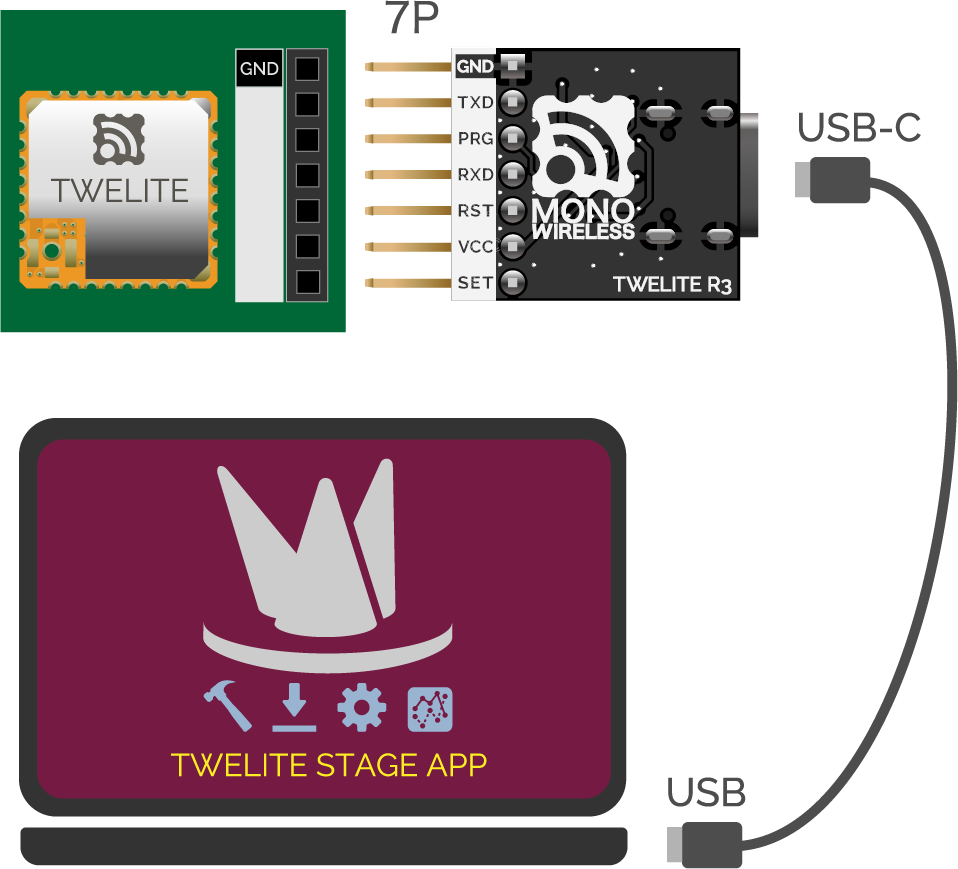
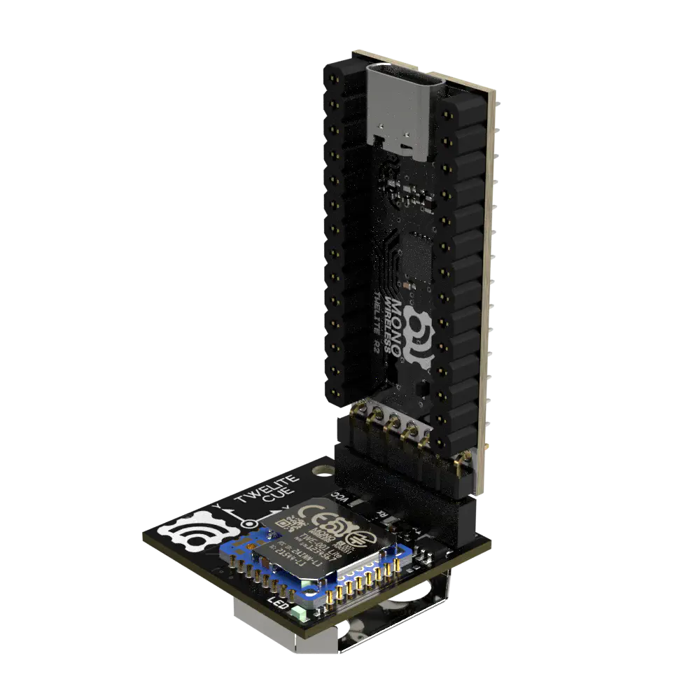
For TWELITE
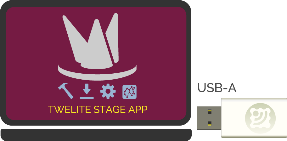
For MONOSTICK
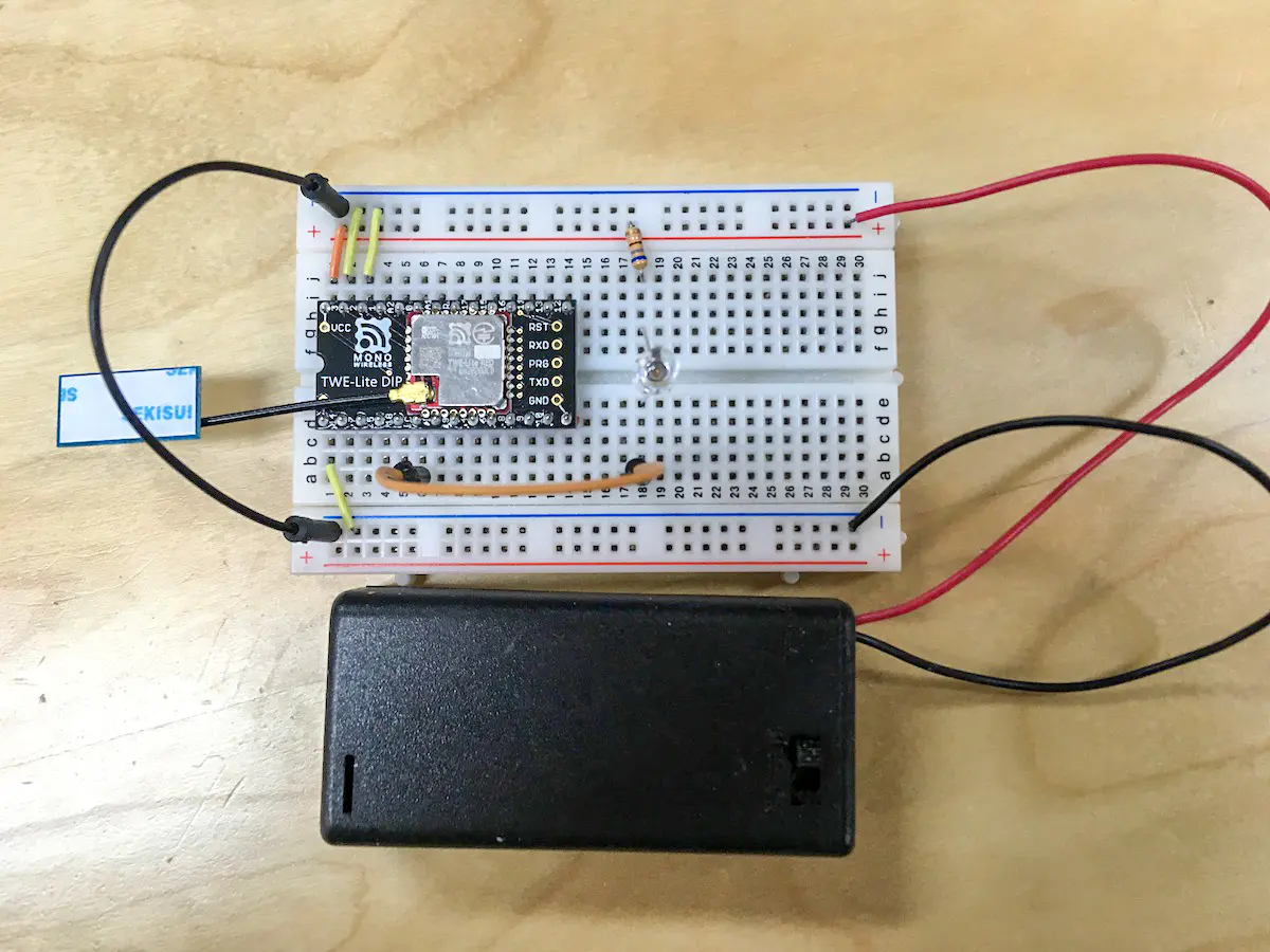
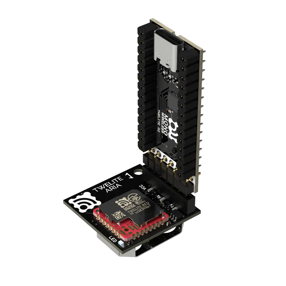
Attach the TWELITE R series to the 7P interface prepared on the parent board and connect to the PC using a USB cable.
Connect the MONOSTICK to the PC’s USB port. TWELITE R series is not required.
Connection between TWELITE (SMD) and PC
Connection between MONOSTICK and PC
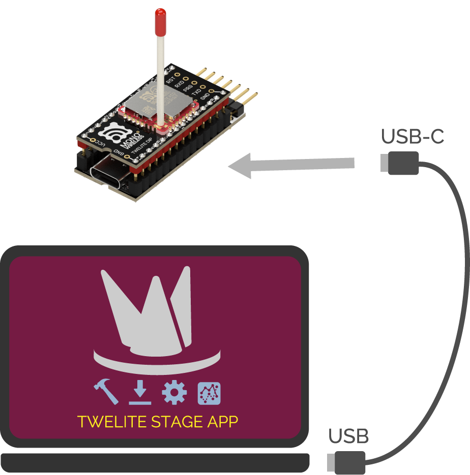
For TWELITE DIP (BLUE/RED)
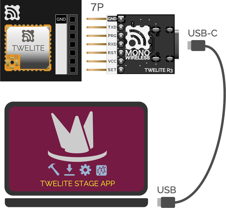
For Others
Attach to TWELITE R series and connect to the PC using a USB cable.
For TWELITE series with 7P interface, attach TWELITE R series and connect to the PC using a USB cable.
Connection between TWELITE DIP (BLUE/RED) and PC
Connection between other TWELITE series and PC
Switching to Interactive Mode
Interactive mode cannot be used while TWELITE is in sleep mode.
When Using TWELITE STAGE
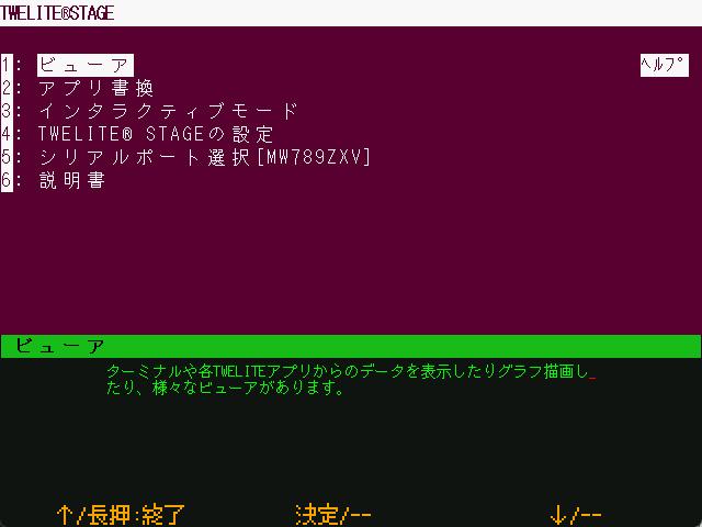
TWELITE STAGE APP is an integrated development tool that includes firmware writing and configuration of TWELITE, as well as a function to display received data.
TWELITE STAGE APP is included in TWELITE STAGE SDK. Please download TWELITE STAGE SDK.
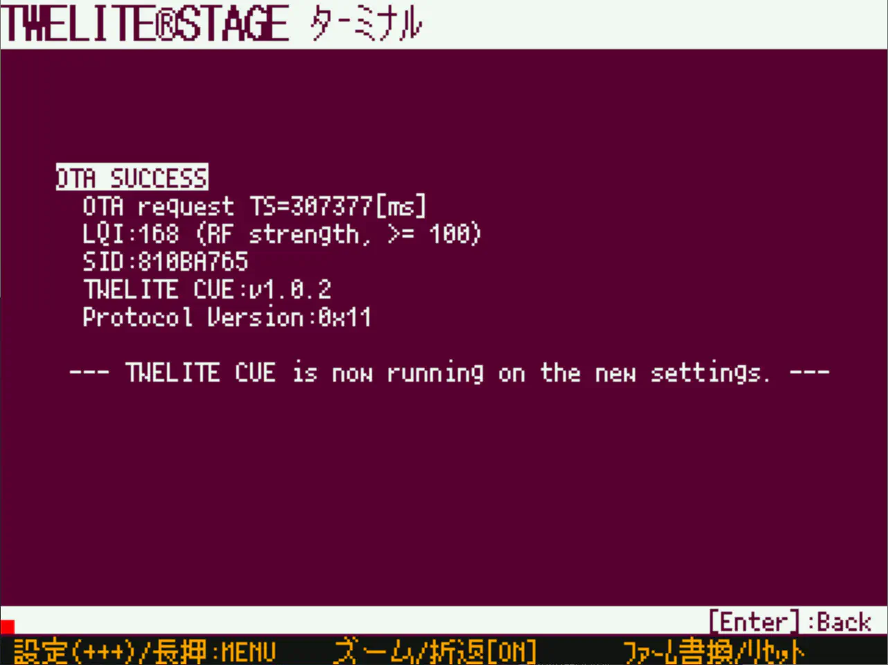
Launch terminal software on the PC (communication settings: 115200bps/8-N-1)
Reset TWELITE.
Slowly press the + key on the PC keyboard three times (interval 0.2 to 1 second). If it does not work well, keep entering + repeatedly.
To exit interactive mode, press + three times again.
Entering the + key from the numeric keypad may fail. Please use the main + key on the keyboard.
Operation of Interactive Mode
Interactive mode displays a screen like the following.
--- CONFIG/TWELITE APP V1-00-2/SID=0x81000038/LID=0x78 ---
 a: set Application ID (0x67720102)
 i: set Device ID (--)
 c: set Channels (18)
 t: set mode4 sleep dur (1000ms)
 y: set mode7 sleep dur (10s)
 f: set mode3 fps (32)
---
 S: save Configuration
 R: reset to Defaults
The displayed content varies depending on the firmware type and version.
Terminal software that does not support escape sequences may display incorrectly.
Steps
Select value: press the first letter alphabet
Specify value: input the value
Confirm value: press Enter
Save value: press S (uppercase)
Apply value: restart TWELITE
Values in parentheses indicate the current setting.
Pressing R (uppercase) resets to default values (apply with S).
Example of Operation
To set the Application ID to 0xBEEFCAFE, input as follows:
Input Application ID (HEX:32bit): BEEFCAFE
To apply the settings, save the content with the S command and then restart the device.
Common Settings for TWELITE APPS
Frequency channel, application ID, device ID, retry count, and transmission output settings are common to TWELITE APPS.
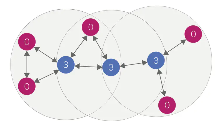
Application ID and Frequency Channel
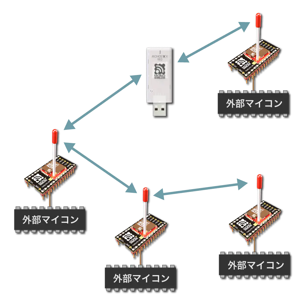
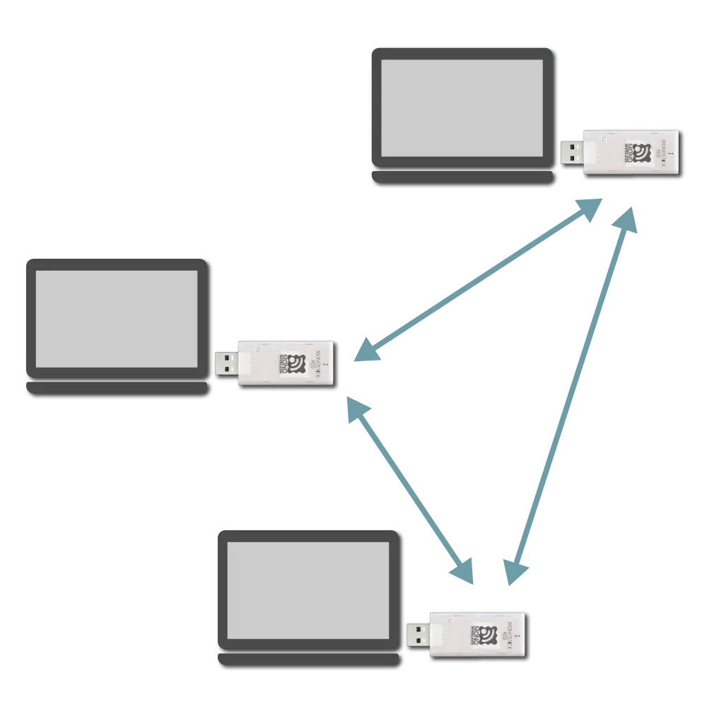
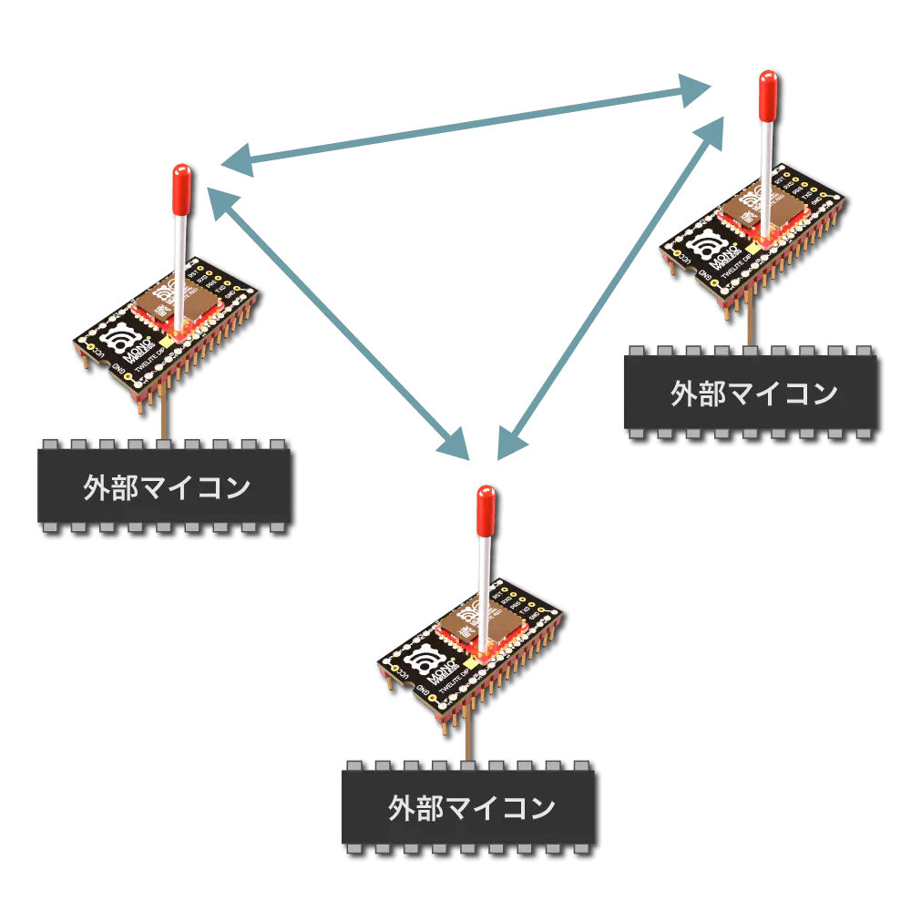
Image of Grouping
Devices must have the same application ID and frequency channel to communicate.
a: Application ID
Setting the same value to all devices communicating allows logical network separation.
TWELITE discards packets received from devices with different application IDs. Therefore, multiple groups can be established within the same frequency channel.
Even if the application ID is the same, if the frequency channel is the same, packet interference cannot be avoided. Please separate frequency channels as much as possible.
If the number of groups is 16 or less, it is recommended to separate both frequency channels and application IDs for each group.
Values with consecutive 0 or F in the upper or lower 2 bytes cannot be set (0xFFFF????/0x0000????/0x????FFFF/0x????0000).
When setting values equal to or greater than 0x80000001, be sure to use the serial number engraved on your TWELITE device.
As long as everyone follows this rule, everyone can obtain a unique application ID.
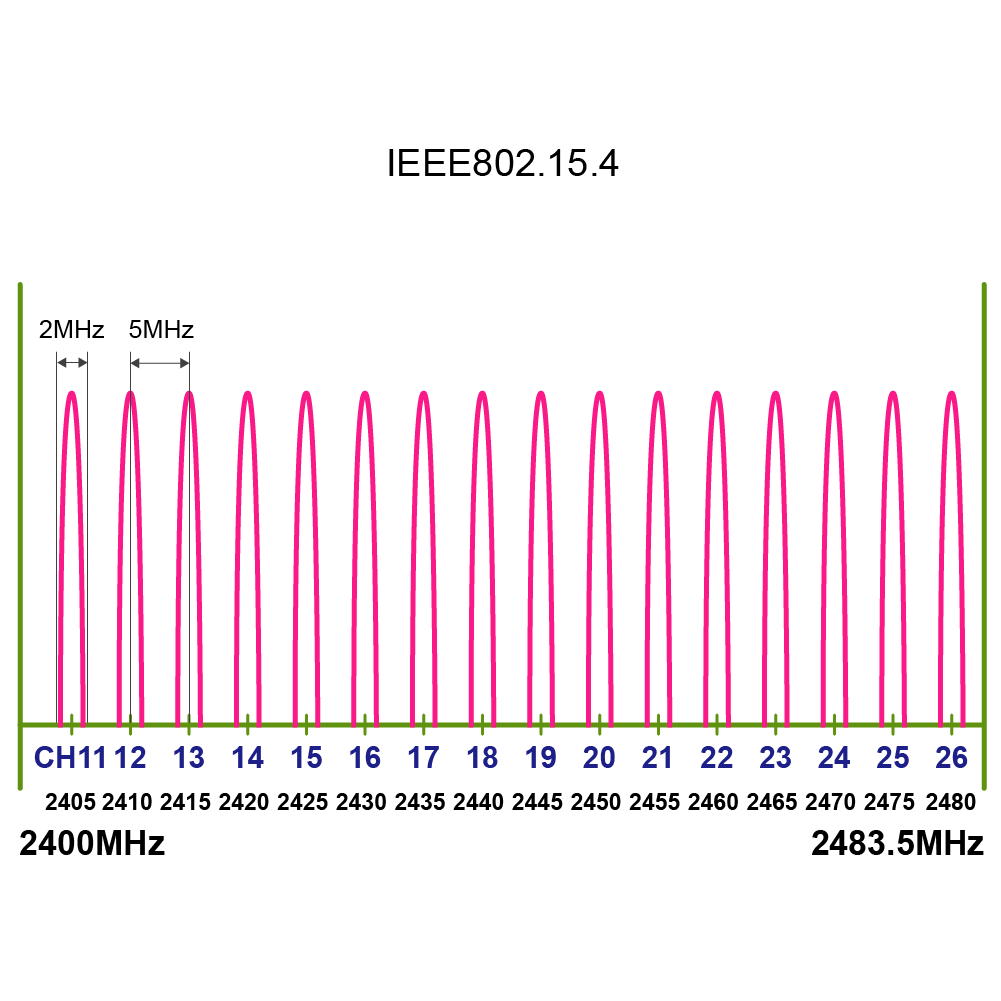
c: Frequency Channel
Setting the same value to all devices communicating allows physical network separation.
TWELITE conforms to the IEEE802.15.4 standard and divides the 2.4GHz band into 16 channels.
List of Frequency Channels
To change the frequency channel, press c (lowercase).
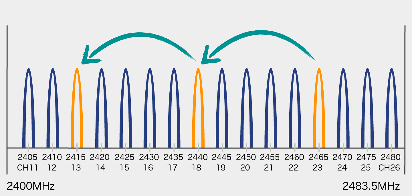
Use of Channel Agility (usually not recommended)
Operation Image
By specifying multiple channels separated by commas, channel agility can be enabled.
Channel agility improves communication success rate in poor communication environments by switching multiple frequency channels at regular intervals during communication.
Up to 3 channels can be specified simultaneously. The specified channels are switched in order at regular intervals for transmission. The receiver also switches channels in order at regular intervals for reception.
Reception is not possible during channel switching. In normal communication environments, reliability is lower than specifying a single channel. Since the number of transmissions from the child device needs to be increased, it is a wasteful method in terms of battery consumption. However, use it when you want to handle situations where certain channels become completely unusable. Normally, it is recommended to specify a single channel after identifying a channel with less interference in advance.
Default Values for Each TWELITE APP
TWELITE APPS
Application ID
Frequency Channel
Super Simple! Standard App (App_Twelite)
0x67720102
18
Remote Control App (App_IO)
0x67720107
16
Serial Communication App (App_Uart)
0x67720103
18
Wireless Tag App (App_Tag)
0x67726305
15
Pulse App (App_PAL)
0x67726305
15
Queue App (App_CUE)
0x67720102
18
Aria App (App_ARIA)
0x67720102
18
Parent/Relay App (App_Wings)
0x67720102
18
i: Logical Device ID
The logical device ID is used to identify each device. You can assign logical IDs to each device.
Image of Assigning Logical Device ID
When using multiple child devices for one parent device, assign different IDs (1 to 100) to each child device.
There is a reported bug with the TWELITE STAGE 202508 Japanese interactive mode compatible version for TWELITE BLUE/RED (binaries with *J, not GOLD version) where the logical device ID value cannot be changed in some cases.
The cause is under investigation. Please use the English version without the *J suffix.
x: Transmission Output and Retry Count
You can weaken the transmission output to narrow the effective radio transmission range. However, power consumption does not change, so normally use the maximum output.
Weakening the output may cause the signal not to reach when needed.
If you need to weaken the output to narrow the reach, it usually indicates a problem in system design. Please properly separate the network by frequency channel and application ID.
Retry count refers to the number of additional transmissions per one transmission request. Setting retry count may improve data arrival rate in poor communication environments. However, communication time and power consumption increase accordingly.
In interactive mode, input a two-digit number.
Tens place: retry count
1 to 9 times
0 is the default value for each app
F disables retry
Ones place: transmission output
3 is the strongest
2/1/0 each step down reduces output by -11.5dB
Examples
32 → Retry 3 times, output one level weaker
93 → Retry 9 times, maximum output
The theoretical transmission distance is 6dB. The transmission distance is expected to be about one-fourth when output is reduced by one level. However, actual distance depends on noise and obstacles.
Resetting Settings
Some settings may interfere with operation (such as baud rate changes).
For settings that differ between apps, please see the following pages.
1 - TWELITE APPS (Unified) Manual
Unified firmware that consolidates all TWELITE APPS
Mainly for the TWELITE GOLD series, this firmware integrates TWELITE APPS such as the Extremely Simple! Standard App App_Twelite, allowing functionality to be switched without rewriting.
1.1 - TWELITE APPS (Unified) Manual
Latest Edition
TWELITE_Apps is a firmware that integrates TWELITE APPS such as the Extremely Simple! Standard App App_Twelite, allowing users to switch functionalities without rewriting. It’s like an assortment pack of TWELITE APPS.
It comes pre-installed on TWELITE STICKs at the time of shipment.
Overview
The unified firmware bundles the following TWELITE APPS:
A menu like the following will display a list of TWELITE APPS:
[TWELITE AppSel/v0-02-1/SID=8300051A/SAVE=04-12-01]
M: AppSel           App selector (this screen)
R: Revert to DEFAULT(*DEF)
A: App_Twelite      Standar app. (App_Twelite)
B: App_IO           App for remote. (App_IO)
C: App_UART         App for SERIAL comm. (App_Uart)
D: App_Wings        Parent/Repeater (App_Wings)(*DEF)
E: App_OTA          OTA Apps for ARIA/CUE.

[!]:Reset [R]:Revert [$]:LANG=English
3. Select a TWELITE APP
Just like in Interactive Mode, you can switch to a TWELITE APP by entering the command ID letter.
For example, in the above example, entering C switches to App_Uart.
[App_UART / App for SERIAL comm. (App_Uart)]
Designed for UART (Serial) communications. UART is commonly used on MCUs.

=== Please select from the list below. Save the startup application. ===
1: Normal
2: for TWELITE UART

[BS]:Back
On the switching screen, select a variation if necessary.
After that, the TWELITE APP will switch and reset immediately.
Initialize TWELITE APP
On the TWELITE APP list screen, entering R will revert to the default TWELITE APP.
! Clear Save Data? The next key will perform:
S: Clear App Selection.
!: Clear ALL SAVE DATA.

[BS]:Back
If you enter S, only the switch will occur. If you enter !, the settings will also be initialized along with the switch.
2 - Extremely Simple! Standard App Manual
Transmission of digital and analog signals
The input/output states of parent and child devices are synchronized.
An all-in-one package supporting 4 digital ports, 4 analog ports, serial, and I2C.
Simplified with versatile features, but does not focus on processing speed, responsiveness, or power saving.
Sends input status to parent every 10 seconds, and disables reception to always enter power-saving mode
✅
127
O: Not connected (OPEN), G: Connected to GND
Initial state is Child: Continuous mode.
The initial Logical Device ID (LID) used to identify the device varies depending on the mode.
Only in Parent or Repeater modes, the LID can be switched via Interactive Mode.
Please use 121 for Parent and 122 for Repeater.
Handling of unused AIx ports
In Child: Continuous / Child: Continuous 0.03s / Parent: Continuous modes, please connect unused AIx ports to VCC.
Unused AIx ports report undefined values. These modes send data when there is a change in input signals, which may cause unnecessary data transmission.
Parent Device
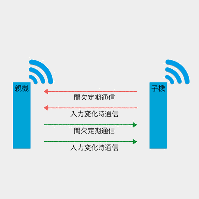
Continuous Mode
Parent: Continuous Mode
When input signals change or every 1 second, data is sent to all child devices.
It always waits for data sent from child devices, providing good responsiveness but continuously consuming power.
Reception: Always waiting
Transmission: On input change / every 1 second
Disabling periodic transmission
You can disable periodic transmission every 1 second by setting option bit 0x00000002 in Interactive Mode.
Child Device
Continuous Mode
Child: Continuous Mode
When input signals change or every 1 second, data is sent to all parent devices.
It always waits for data sent from parent devices, providing good responsiveness but continuously consuming power.
Communication image with parent device
Reception: Always waiting
Transmission: On input change / every 1 second
Disabling periodic transmission
You can disable periodic transmission every 1 second by setting option bit 0x00000002 in Interactive Mode.
Child: Continuous 0.03s Mode
This mode shortens the periodic transmission interval of Child: Continuous Mode from 1 second to 0.03 seconds.
Although it always waits for data sent from the parent, the communication from child to parent occupies the bandwidth, making the parent’s input response slower. It continuously consumes power.
Communication image with parent device
Reception: Always waiting
Transmission: On input change / every 0.03 seconds
Because a single child occupies most of the bandwidth, please avoid using multiple children simultaneously as much as possible.
Intermittent Mode
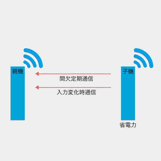
Child: Intermittent 1s Mode
When input signals change or every 1 second, power-saving mode is canceled and data is sent to all parent devices.
Reception is disabled, so control from the parent device is not possible. This mode has excellent power-saving performance.
Communication image with parent device
Reception: Disabled
Transmission: On input change / every 1 second
Child: Intermittent 10s Mode
When input signals change or every 10 seconds, power-saving mode is canceled and data is sent to all parent devices.
Reception is disabled, so control from the parent device is not possible. This mode has excellent power-saving performance.
Communication image with parent device
Reception: Disabled
Transmission: On input change / every 10 seconds
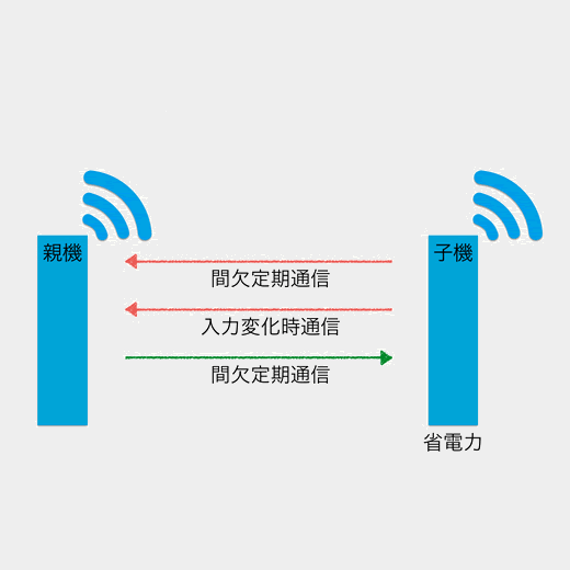
Child: Intermittent Reception 1s Mode
When input signals change or every 1 second, power-saving mode is canceled and data is sent to all parent devices.
Reception is also performed every 1 second. It has excellent power-saving performance but is inferior to Child: Intermittent 1s Mode.
Communication image with parent device
Reception: Every 1 second
Transmission: On input change / every 1 second
Because reception is intermittent, the parent device must operate continuously.
Repeater
Continuous Mode
Repeater: Continuous Mode
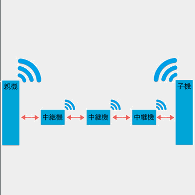
The repeater forwards received packets.
Up to three repeaters can be installed between parent and child devices, but increasing repeaters increases the number of packets, which may cause interference.
Image of relaying
Reception: Always waiting
Transmission: On reception
You can also add repeater functionality to child devices. Specify 0x00008000 in the option bits of Interactive Mode.
2.1.3 - Alternative Baud Rate Setting for Extremely Simple! Standard App
Changing the baud rate used for UART communication
The Extremely Simple! Standard App (App_Twelite) uses 115200 bps as the default baud rate for UART communication, but this can be changed.
Enabling Alternative Baud Rate Setting
You can enable the alternative baud rate setting by connecting the BPS pin to GND.
The baud rate setting in Interactive Mode indicates the alternative baud rate. If the BPS pin is not connected to GND, the Interactive Mode setting will not be applied.
Interactive Mode uses UART communication. When switching the baud rate of TWELITE, you must adjust the PC side baud rate before using Interactive Mode (Settings in TWELITE STAGE App).
2.1.4 - UART Function of Extremely Simple! Standard App
Data format used in UART function
This explains the data format used in the UART function of the Extremely Simple! Standard App (App_Twelite).
Digital and Analog Input/Output
0x81: Status Notification from Remote Device
Outputs the state of the received input signals.
Data Format
#
Data
Content
Note
char
Header
: only
0
uint8
Source Logical Device ID
1
uint8
Command Number
0x81 only
2
uint8
Packet Identifier
Generated from Application ID
3
uint8
Protocol Version
0x01 only
4
uint8
LQI
0-255
5
uint32
Source Serial ID
0x8???????
9
uint8
Destination Logical Device ID
10
uint16
Timestamp
64 counts per second
12
uint8
Relay Count
13
uint16
Power Supply Voltage
Unit is mV
15
int8
-
(Unused)
16
uint8
Digital Signals
Corresponds to DIx from LSB, 0 is High MSB 1 means periodic transmission
Parent 0x00, Child 0-0x7F, All Children 0x78, Self 0xDB
1
uint8
Packet Identifier
0x88 only
2
uint8
Response Number
Number output to response message
3
uint8
Command Number
Write 0x1, Read 0x2, Read/Write 0x4
4
uint8
I2C Address
7-bit
5
uint8
I2C Command
First command byte
6
uint8
Data Size
0 means none
7
[uint8]
Data
Byte sequence of length \(N\)
uint8
Checksum
LRC8
char
Footer
CR (0x0D/'\r')
char
Footer
LF (0x0A/'\n')
For command number 0x4, specify the data size to read and omit the data. The specified I2C command is written, and the specified amount of data is read.
0x89: I2C Output
Data Format
#
Data
Content
Note
char
Header
: only
0
uint8
Source Logical Device ID
Parent 0x00, Child 0-0x7F, All Children 0x78, Self 0xDB
1
uint8
Packet Identifier
0x89 only
2
uint8
Response Number
Number output to response message
3
uint8
Command Number
Write 0x1, Read 0x2, Read/Write 0x4
4
uint8
Result
Failure 0, Success 1
5
uint8
Data Size
0 means none
6
[uint8]
Data
Byte sequence of length \(N\)
uint8
Checksum
LRC8
char
Footer
CR (0x0D/'\r')
char
Footer
LF (0x0A/'\n')
2.1.5 - Interactive Mode (Extremely Simple! Standard App)
Detailed configuration changes via Interactive Mode
You can perform detailed configuration of the app via Interactive Mode.
This section explains functions specific to the Extremely Simple! Standard App (App_Twelite). For common features, please refer to the TWELITE APPS manual top page.
Interactive Mode cannot be used while TWELITE is sleeping.
Set the Mx pin settings to Child Continuous Mode or Parent/Relay Mode.
Display Example
The following screen is displayed.
--- CONFIG/TWELITE APP V1-08-2/SID=0x8201001f/LID=0x78 ---
 a: set Application ID (0x67720102)
 i: set Device ID (--)
 c: set Channels (18)
 x: set Tx Power (03)
 t: set mode4 sleep dur (1000ms)
 y: set mode7 sleep dur (10s)
 f: set mode3 fps (32)
 z: set PWM HZ (1000,1000,1000,1000)
 o: set Option Bits (0x00000000)
 b: set UART baud (38400)
 p: set UART parity (N)
---
 S: save Configuration
 R: reset to Defaults
Overrides the intermittent interval of the child intermittent 1-second mode from 1 second to another value. Unit is milliseconds.
Setting 0 disables periodic wakeup by timer. In this case, wakeup occurs on falling edge of DIx but not on rising edge.
y: Child Intermittent 10-second Mode Interval
Overrides the intermittent interval of the child intermittent 10-second mode from 10 seconds to another value. Unit is seconds.
Setting 0 disables periodic wakeup by timer. In this case, wakeup occurs on falling edge of DIx but not on rising edge.
f: Child Continuous 0.03-second Mode Cycle
Overrides the number of transmission requests per second from 32 times to 4/8/16 times. Retry count is not included.
z: PWMx Frequency
If one value is specified, it overrides the frequency of all PWM ports. If specified by comma separation, individual values for PWM1 to PWM4 can be overridden.
o: Option Bits
Specify a 32bit number. Enables settings linked to each bit.
Overrides the alternative baud rate selected when the BPS pin is connected to GND at startup from 38400bps.
Values can be selected from 9600/19200/38400/57600/115200/230400. Specifying other values may cause errors.
This setting is not applied when the BPS pin is left open at startup. The baud rate is fixed at 115200bps.
This is a specification to prevent situations where Interactive Mode becomes unusable due to baud rate changes.
p: UART Parity
N means no parity, O means odd parity, and E means even parity.
Data bits are fixed to 8, stop bits to 1. Hardware flow control cannot be set.
Details of Option Bits
Explanation of settings linked to each bit of the Option Bits value.
00000001: Low Latency Mode
Low Latency Mode shortens the delay on the receiver side by quickly transmitting after detecting changes in DIx.
Low Latency Mode Operation
In the initial state, there is a delay of about 30-70ms until DIx is reflected on DOx. Low Latency Mode shortens this delay to about 3-10ms by simplifying processing to avoid chattering and wireless packet interference.
Falling edge detection uses interrupts
After detection, no new detection occurs for about 100ms
Rising edge detection uses periodic judgment
Transmission occurs if 5 consecutive readings are High at 1ms intervals
(Initially, transmission occurs if 5 consecutive readings are High at 4ms intervals)
No transmission or retransmission delay is set at detection; the wireless packet is immediately sent
Typical delays are about 3-5ms for falling edges and about 10ms for rising edges
Actual delay varies due to transmission/reception failures, etc.
In intermittent mode, the time from wakeup to transmission is also shortened
00000002: Disable Periodic Transmission
Disables periodic transmission every 1 second in continuous mode for child devices.
00000004: Disable Periodic Transmission and UART Output
For child devices: disables periodic transmission every 1 second in continuous mode and stops UART output of received data.
00000010: Disable Transmission on AIx Change
For child devices: disables transmission when AIx input changes in continuous mode.
Since released AIx ports report undefined values, connect them to VCC when analog input is not used. This option allows omission of connection to VCC.
00000020: Disable AIx Value
Sends packets treating unused ports as 0xFFFF without using ADC measurement values.
00000040: Change PWMx Calculation Formula
By default, adjusted output for volume control is applied to PWMx.
This option disables that and outputs full scale for inputs below 1.8V.
Duty Cycle Calculation Formula
Duty cycle \(duty\) can be expressed using input voltage \(V_{input}\) and power supply voltage \(V_{cc}\) as in (1).
3.1.1.1.1.4.3 - Output from Aria App (Parent and Repeater App)
Output format when data is received from the Aria app
TWELITE ARIA Mode
Previously, instructions on how to interpret data using Python were provided here, but now the official library is distributed.
Please use MWings for Python.
3.1.1.1.1.4.4 - Details of Output from Pal, Cue, and Aria Apps (Parent and Repeater App)
Details of the common output format for Pal, Cue, and Aria apps
Data received from child devices of Pal, Cue, and Aria apps are output according to a common format. This section details that format. For specific output examples of each app, see the app pages.
Byte sequence of length \(N\) (recommended \(N\leqq80\))
uint8
Checksum
LRC8
char
Footer
CR (0x0D/'\r')
char
Footer
LF (0x0A/'\n')
3.1.1.1.2.3 - Input to Remote Control App (Parent and Repeater Apps)
Commands for controlling Remote Control App output
From v1.3 onwards, you can control the output of Remote Control App.
Explanation of data format used in the UART function of Remote Control App (App_IO).
Digital Input and Output
0x81: Status Notification from the Remote Device
Outputs the state of the received input signal.
Data Format
#
Data
Description
Remarks
char
Header
: only
0
uint8
Source Logical Device ID
1
uint8
Command Number
0x81 only
2
uint8
Packet Identifier
0x0F only
3
uint8
Protocol Version
0x01 only
4
uint8
LQI
0-255
5
uint32
Source Serial ID
0x8???????
9
uint8
Destination Logical Device ID
10
uint16
Timestamp
64 counts per second, MSB is internal flag
12
uint8
Relay Count
13
uint16
Digital Signal
Corresponds to Ix from LSB, 0 is High
15
uint16
Digital Signal Mask
Corresponds to Ix from LSB, 1 means valid
17
uint16
Digital Signal Flag
Corresponds to Ix from LSB, 1 means interrupt
19
uint8
Unused
For internal management
uint8
Checksum
LRC8
char
Footer
CR (0x0D/'\r')
char
Footer
LF (0x0A/'\n')
Example Output Data
:01810F01DB8630000200645F000040004F00400049
Interpretation of the Above Data
#
Data
Description
Value
:
char
Header
:
01
0
uint8
Source Logical Device ID
0x78
81
1
uint8
Command Number
0x81
0F
2
uint8
Packet Identifier
0x15
01
3
uint8
Protocol Version
0x01
DB
4
uint8
LQI
219/255
86300002
5
uint32
Source Serial ID
0x6300002
00
9
uint8
Destination Logical Device ID
0x00
645F
10
uint16
Timestamp
Approx. 401 seconds
00
12
uint8
Relay Count
0
0040
13
uint16
Digital Signal
I7 is Low
004F
15
uint16
Digital Signal Mask
I7,I1-I4 are valid
0040
17
uint16
Digital Signal Flag
I7 changed due to interrupt
00
19
uint8
Unused
49
uint8
Checksum
0x49
char
Footer
\r
char
Footer
\n
0x80: Remote Device Output Change
Controls the output signals of the remote device.
Data Format
#
Data
Description
Remarks
char
Header
: only
0
uint8
Destination Logical Device ID
Parent 0x00, Child 0x01-0x64, All Children 0x78
1
uint8
Command Number
0x80 only
2
uint8
Format Version
0x01 only
3
uint16
Digital Signal
Corresponds to Ox from LSB, 0 is High
5
uint16
Digital Signal Mask
Corresponds to Ox from LSB, 1 is valid
7
uint16
Unused
0
9
uint16
Unused
0
11
uint16
Unused
0
13
uint16
Unused
0
uint8
Checksum
LRC8
char
Footer
CR (0x0D/'\r')
char
Footer
LF (0x0A/'\n')
3.1.1.1.2.4 - Input to the PAL App (Notification PAL) (Parent and Repeater App)
Commands to control the LED of the Notification PAL
You can control the LED of the Notification PAL.
:0190010004000169[CR][LF]
 ^1^2^3^^^^^^^4^5
No.
Bytes
Meaning
Example Data
Notes
1
1
Destination Logical Device ID
01
Specify the logical device ID of the destination TWELITE PAL. Valid values range from 0x01 to 0x64.
2
1
Command Type
90
3
1
Number of Command Parameters
01
Specify the number of command parameters. For example, set to 1 if specifying one command parameter, or 2 if specifying two.
4
Number of Commands x 4
Command Parameters
00040001
Specify parameters such as events and LED colors. See the command parameters section for details.
5
1
Checksum
69
Calculate the sum of bytes 1 to 4 within 8 bits and take the two’s complement. In other words, the sum of all data bytes plus the checksum byte equals zero within 8 bits. The checksum byte is represented by two ASCII characters. For example, in 00A01301FF123456, the sum 0x00 + 0xA0 + … + 0x56 = 0x4F, and its two’s complement is 0xB1 (i.e., 0x4F + 0xB1 = 0). The checksum can be omitted by using ‘X’ as the checksum.
6
2
Footer
[CR][LF]
Specify [CR] (0x0D) [LF] (0x0A). However, if the checksum is omitted with ‘X’, the footer can also be omitted.
Command Parameters
Combine 4-byte command parameters to specify commands.
0x00: Send Event ID
The TWELITE PAL has predefined behaviors for each received event ID. This parameter sends an event ID to the destination TWELITE PAL to trigger the configured behavior.
To change the behavior for each event, please modify the TWELITE PAL settings.
No.
Bytes
Content
Notes
1
1
Command Parameter ID
0x00
2
1
Destination PAL ID
Specify the destination PAL ID. 0x04: Notification PAL 0xFF: All TWELITE PALs
3
1
Unused
Fixed at 0x00
4
1
Event ID
Specify event ID from 0 to 16
0x01: Send LED Color, Blinking Pattern, and Brightness
Send the LED color, blinking pattern, and brightness to the destination Notification PAL.
No.
Bytes
Content
Notes
1
1
Command Parameter ID
0x01
2
1
Color
0: Red 1: Green 2: Blue 3: Yellow 4: Purple 5: Cyan 6: White 7: Warm White
3
1
Blinking Pattern
0: Always on 1-3: Blinking patterns (higher value means faster blinking)
4
1
Brightness
0: Off 0x01–0x0F: Brightness (higher value means brighter)
0x02: Send Lighting Duration
Send the lighting duration of the Notification PAL’s LED.
This command parameter does not include LED color, blinking pattern, or brightness, so use it in combination with command parameters 0x01 or 0x03.
When using this command parameter, be sure to set the transmission interval longer than the lighting duration.
No.
Bytes
Content
Notes
1
1
Command Parameter ID
0x02
2
1
Unused
Fixed at 0xFF
3
1
Unused
Fixed at 0x00
4
1
Lighting Duration
Specified in seconds (0 means always on)
0x03: Specify LED Color in RGBW
Send the LED lighting color of the Notification PAL in RGBW.
Cannot be used simultaneously with command parameters 0x00 and 0x01.
No.
Bytes
Content
Notes
1
1
Command Parameter ID
0x03
2
1
Unused
Fixed at 0xFF
3
2
LED Lighting Color
Specify 4 bits each for RGBW in order from LSB.
Higher value means brighter.
0x04: Specify Blinking Parameters
Send the blinking cycle and duty of the Notification PAL’s LED.
This command parameter does not include LED color, so use it in combination with command parameter 0x03.
Cannot be used simultaneously with command parameters 0x00 and 0x01.
No.
Bytes
Content
Notes
1
1
Command Parameter ID
0x04
2
1
Unused
Fixed at 0xFF
3
1
Blinking Time Ratio
Specify from 0x00 to 0xFF.
Higher value means longer ON time per cycle.
0x7F means ON for half of the cycle.
4
1
Blinking Cycle
Specify from 0x00 to 0xFF.
Each increment increases the blinking cycle by about 0.04s.
0x17 corresponds to a 1-second cycle.
Command Examples
Example 1: Send Event
Command example to send event 1 to the NOTICE PAL with logical device ID 1.
:0190010004000169
 ^1^2^3^4^5^6^7^8
No.
Bytes
Meaning
Example Data
Explanation of Example Data
Notes
1
1
Destination Logical Device ID
01
Logical device ID of the destination is 0x01
2
1
Command Type
90
0x90 command
Fixed at 90
3
1
Number of Commands
01
One command
4
1
Command ID
00
Command 00
5
1
Destination PAL ID
04
Sent to Notification PAL
6
1
Unused
00
7
1
Event ID
01
Event 1
0x00 to 0x10
8
1
Checksum
69
Example 2: Send LED Lighting Color to Notification PAL
Command to send LED lighting color with brightness 8 and slow blinking white to the NOTICE PAL with logical device ID 1.
:019001010601085E
 ^1^2^3^4^5^6^7^8
No.
Bytes
Meaning
Example Data
Explanation of Example Data
Notes
1
1
Destination Logical Device ID
01
Logical device ID of the destination is 0x01
2
1
Command Type
90
0x90 command
Fixed at 90
3
1
Number of Commands
01
One command
4
1
Command Parameter ID
01
Command parameter ID 0x01
5
1
Color
06
White
6
1
Blinking Pattern
01
Blinking
7
1
Brightness
08
Brightness 8
Range 0x00 to 0x0F
8
1
Checksum
5E
Example 3: Send LED Lighting Color and Lighting Duration to Notification PAL
Command to light up purple and turn off after 1 second for the NOTICE PAL with logical device ID 1.
When testing this command, be sure to set the transmission interval longer than the lighting duration.
3.1.1.2 - Repeater Mode of Parent and Repeater App
Retransmit data received from Child or Parent
In repeater mode, retransmitting received packets can extend the communication range between Child and Parent.
When relaying, the order of packets received by the Parent may be rearranged.
If there are Children sending continuously at short intervals such as about 100ms, the relay may not keep up. Please thoroughly verify in a production environment before use.
Example Settings
To use as a repeater, set the Operating Mode in interactive mode to 1 or higher.
Relay Methods
TWELITE NET provides two major relay methods for wireless packet delivery, as shown in the table below, which differ depending on the application. This app can identify and relay packets of the applications shown in the table below.
Relay Method
Supported Applications
Simple Net
Extremely Simple! Standard App, Remote Control App, Serial Communication App, ACT
Relay Net
Wireless Tag App, PAL App, CUE App
Relay Using Simple Net
When relaying applications using Simple Net, setting the operating mode to 1 or higher allows up to three relays.
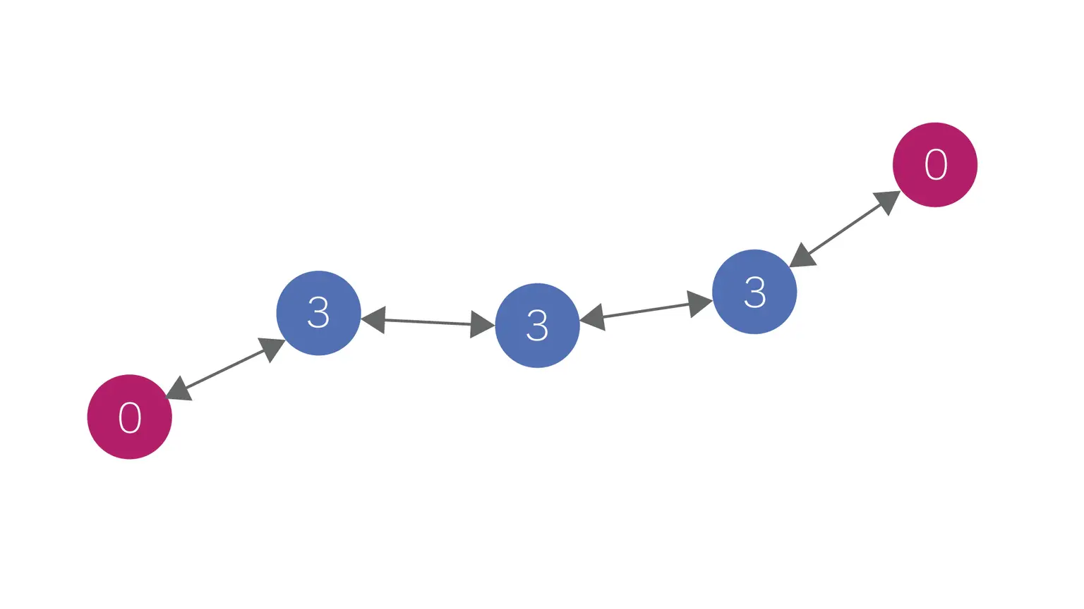
For example, in case 1., if there are up to 3 Repeaters between the Parent and Child, data will reach the Parent, but in case 2., if there are 4 or more Repeaters, data will not reach the Parent.
1. Child  --->  Repeater  --->  Repeater  --->  Repeater  --->  Parent
   → Parent can receive Child's data relayed 3 times.
2. Child  --->  Repeater  --->  Repeater  --->  Repeater  --->  Repeater  -x->  Parent
   → Stops relaying at the 4th relay.
Relaying with Simple Net basically uses broadcast communication and relays all received packets. The advantage is that communication to form and maintain the relay network is not necessary, but the disadvantage is that communication volume can explode as the number of Repeaters increases.
For relaying data of applications using Relay Net with one stage of relay, set the operating mode value to 1.
When performing multiple relays, increase the operating mode setting value as the distance from the Parent increases. (It is acceptable if the setting values are in ascending order even if some values are skipped.)
The maximum number of relays for this method is up to 63 times.
Example 1: One relay\
Child ---> Repeater (Operating Mode: 1) ---> Parent

Example 2: Two relays\
Child  --->  Repeater (Operating Mode: 2) --->  Repeater (Operating Mode: **1**)  --->  Parent

Example 3: Three relays\
Child ---> Repeater (Operating Mode: 6) ---> Repeater (Operating Mode: 3) ---> Repeater (Operating Mode: 1) ---> Parent
Relay Net is a tree-type network designed to efficiently deliver upstream packets. Repeaters search for an upper layer (Parent or Repeater with a smaller operating mode setting) and relay to one discovered upper layer device.
Therefore, even if the number of Repeaters increases, the communication volume is less likely to become large compared to Simple Net, but communication occurs to discover and maintain the connection destination.
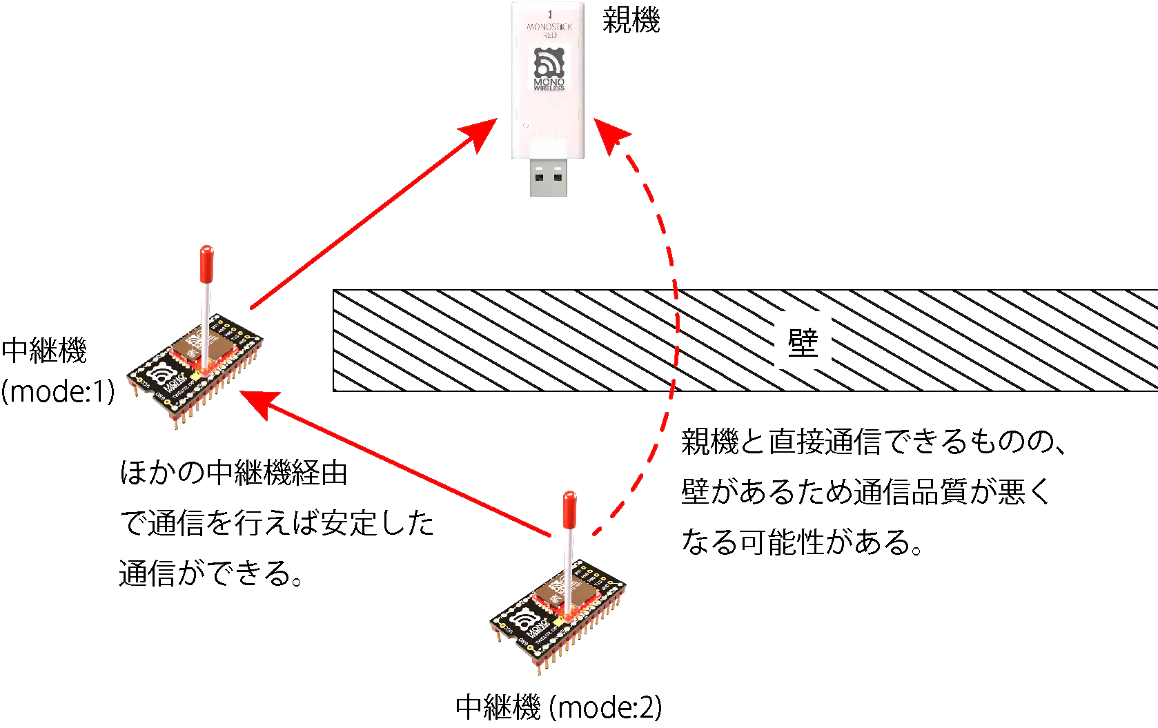
When Performing Static Routing (Directly Specifying Relay Destination)
When relaying with Relay Net, considering the layout as shown in the figure below, Repeater 2 automatically selects either the Parent or Repeater 1 as the connection destination.
Basically, fewer relays tend to have a higher delivery rate to the Parent, but if the Parent is selected as the connection destination for Repeater 2, communication quality may deteriorate due to obstacles between Parent and Repeater 2, resulting in a lower delivery rate to the Parent than when relaying through Repeater 1.
Therefore, this app has a function (static routing function) to specify the connection destination of Repeaters by TWELITE serial number.
When performing static routing, set the route from Repeater 2 to Repeater 1 statically, or set all routes statically.
Setting all routes increases the amount of configuration and does not support redundancy for situations such as Repeater failure or changes in radio conditions, but it eliminates the time to determine the upper communication destination and allows prompt relay operation.
To perform static routing, set the connection destination as shown in the table below: Repeater 1’s connection destination is the Parent’s SID, and Repeater 2’s connection destination is Repeater 1’s SID.
Connection Destination (A: Access Point Address) Setting Example
Operating Mode (l:Mode) Setting Example
Parent
810F155E
-
0
Repeater 1
810E18E8
810F155E (Parent’s SID)※
1
Repeater 2
810F17FF
810E18E8 (Repeater 1’s SID)
2
※ If you only want to deal with effects caused by walls as shown in the figure, this setting is unnecessary.
3.1.2 - Interactive Mode (Parent and Repeater App)
Detailed configuration changes via Interactive Mode
You can configure advanced settings of the app in Interactive Mode.
This section describes functions specific to the Parent and Repeater App (App_Wings). For common functions, refer to the top page of the TWELITE APPS manual.
Display Example
A screen like the following will appear:
[CONFIG MENU/App_Wings:ROUTER:0/v1-03-2/SID=8300051A]
a: (0x67720102) Application ID [HEX:32bit]
c: (18        ) Channel(s)
x: (      0x03) RF Power/Retransmissions [HEX:8bit]
b: (115200,8N1) UART Baud Alt. [XXXXX]
o: (0x00000001) Option bits [HEX:32bit]
t: (0xA5A5A5A5) Encryption key [HEX: 32bits]
m: (         1) [1] default, [2-63] to specify the layer of the LayerNetwork.
A: (0x00000000) Relay destination [HEX:32bit]

 [ESC]:Exit [!]:Reset System [*]:Extr Menu [:]:AppSel
When performing static routing in repeater mode, specify the Serial ID (0x8???????) of the upstream device. If set to 0x00000000, it will search automatically.
Details of Option Bits
This section explains the settings associated with each bit in the Option Bits value.
3.2.1.1.1.4.3 - Output from Aria App (Parent and Repeater App)
Output format when data is received from the Aria app
TWELITE ARIA Mode
Previously, instructions on how to interpret data using Python were provided here, but now the official library is distributed.
Please use MWings for Python.
3.2.1.1.1.4.4 - Details of Output from Pal, Cue, and Aria Apps (Parent and Repeater App)
Details of the common output format for Pal, Cue, and Aria apps
Data received from child devices of Pal, Cue, and Aria apps are output according to a common format. This section details that format. For specific output examples of each app, see the app pages.
Byte sequence of length \(N\) (recommended \(N\leqq80\))
uint8
Checksum
LRC8
char
Footer
CR (0x0D/'\r')
char
Footer
LF (0x0A/'\n')
3.2.1.1.2.3 - Input to the PAL App (Notification PAL) (Parent and Repeater App)
Commands to control the LED of the Notification PAL
You can control the LED of the Notification PAL.
:0190010004000169[CR][LF]
 ^1^2^3^^^^^^^4^5
No.
Bytes
Meaning
Example Data
Notes
1
1
Destination Logical Device ID
01
Specify the logical device ID of the destination TWELITE PAL. Valid values range from 0x01 to 0x64.
2
1
Command Type
90
3
1
Number of Command Parameters
01
Specify the number of command parameters. For example, set to 1 if specifying one command parameter, or 2 if specifying two.
4
Number of Commands x 4
Command Parameters
00040001
Specify parameters such as events and LED colors. See the command parameters section for details.
5
1
Checksum
69
Calculate the sum of bytes 1 to 4 within 8 bits and take the two’s complement. In other words, the sum of all data bytes plus the checksum byte equals zero within 8 bits. The checksum byte is represented by two ASCII characters. For example, in 00A01301FF123456, the sum 0x00 + 0xA0 + … + 0x56 = 0x4F, and its two’s complement is 0xB1 (i.e., 0x4F + 0xB1 = 0). The checksum can be omitted by using ‘X’ as the checksum.
6
2
Footer
[CR][LF]
Specify [CR] (0x0D) [LF] (0x0A). However, if the checksum is omitted with ‘X’, the footer can also be omitted.
Command Parameters
Combine 4-byte command parameters to specify commands.
0x00: Send Event ID
The TWELITE PAL has predefined behaviors for each received event ID. This parameter sends an event ID to the destination TWELITE PAL to trigger the configured behavior.
To change the behavior for each event, please modify the TWELITE PAL settings.
No.
Bytes
Content
Notes
1
1
Command Parameter ID
0x00
2
1
Destination PAL ID
Specify the destination PAL ID. 0x04: Notification PAL 0xFF: All TWELITE PALs
3
1
Unused
Fixed at 0x00
4
1
Event ID
Specify event ID from 0 to 16
0x01: Send LED Color, Blinking Pattern, and Brightness
Send the LED color, blinking pattern, and brightness to the destination Notification PAL.
No.
Bytes
Content
Notes
1
1
Command Parameter ID
0x01
2
1
Color
0: Red 1: Green 2: Blue 3: Yellow 4: Purple 5: Cyan 6: White 7: Warm White
3
1
Blinking Pattern
0: Always on 1-3: Blinking patterns (higher value means faster blinking)
4
1
Brightness
0: Off 0x01–0x0F: Brightness (higher value means brighter)
0x02: Send Lighting Duration
Send the lighting duration of the Notification PAL’s LED.
This command parameter does not include LED color, blinking pattern, or brightness, so use it in combination with command parameters 0x01 or 0x03.
When using this command parameter, be sure to set the transmission interval longer than the lighting duration.
No.
Bytes
Content
Notes
1
1
Command Parameter ID
0x02
2
1
Unused
Fixed at 0xFF
3
1
Unused
Fixed at 0x00
4
1
Lighting Duration
Specified in seconds (0 means always on)
0x03: Specify LED Color in RGBW
Send the LED lighting color of the Notification PAL in RGBW.
Cannot be used simultaneously with command parameters 0x00 and 0x01.
No.
Bytes
Content
Notes
1
1
Command Parameter ID
0x03
2
1
Unused
Fixed at 0xFF
3
2
LED Lighting Color
Specify 4 bits each for RGBW in order from LSB.
Higher value means brighter.
0x04: Specify Blinking Parameters
Send the blinking cycle and duty of the Notification PAL’s LED.
This command parameter does not include LED color, so use it in combination with command parameter 0x03.
Cannot be used simultaneously with command parameters 0x00 and 0x01.
No.
Bytes
Content
Notes
1
1
Command Parameter ID
0x04
2
1
Unused
Fixed at 0xFF
3
1
Blinking Time Ratio
Specify from 0x00 to 0xFF.
Higher value means longer ON time per cycle.
0x7F means ON for half of the cycle.
4
1
Blinking Cycle
Specify from 0x00 to 0xFF.
Each increment increases the blinking cycle by about 0.04s.
0x17 corresponds to a 1-second cycle.
Command Examples
Example 1: Send Event
Command example to send event 1 to the NOTICE PAL with logical device ID 1.
:0190010004000169
 ^1^2^3^4^5^6^7^8
No.
Bytes
Meaning
Example Data
Explanation of Example Data
Notes
1
1
Destination Logical Device ID
01
Logical device ID of the destination is 0x01
2
1
Command Type
90
0x90 command
Fixed at 90
3
1
Number of Commands
01
One command
4
1
Command ID
00
Command 00
5
1
Destination PAL ID
04
Sent to Notification PAL
6
1
Unused
00
7
1
Event ID
01
Event 1
0x00 to 0x10
8
1
Checksum
69
Example 2: Send LED Lighting Color to Notification PAL
Command to send LED lighting color with brightness 8 and slow blinking white to the NOTICE PAL with logical device ID 1.
:019001010601085E
 ^1^2^3^4^5^6^7^8
No.
Bytes
Meaning
Example Data
Explanation of Example Data
Notes
1
1
Destination Logical Device ID
01
Logical device ID of the destination is 0x01
2
1
Command Type
90
0x90 command
Fixed at 90
3
1
Number of Commands
01
One command
4
1
Command Parameter ID
01
Command parameter ID 0x01
5
1
Color
06
White
6
1
Blinking Pattern
01
Blinking
7
1
Brightness
08
Brightness 8
Range 0x00 to 0x0F
8
1
Checksum
5E
Example 3: Send LED Lighting Color and Lighting Duration to Notification PAL
Command to light up purple and turn off after 1 second for the NOTICE PAL with logical device ID 1.
When testing this command, be sure to set the transmission interval longer than the lighting duration.
3.2.1.2 - Repeater Mode of Parent and Repeater App
Retransmit data received from Child or Parent
In repeater mode, retransmitting received packets can extend the communication range between Child and Parent.
When relaying, the order of packets received by the Parent may be rearranged.
If there are Children sending continuously at short intervals such as about 100ms, the relay may not keep up. Please thoroughly verify in a production environment before use.
Example Settings
To use as a repeater, set the Operating Mode in interactive mode to 1 or higher.
Relay Methods
TWELITE NET provides two major relay methods for wireless packet delivery, as shown in the table below, which differ depending on the application. This app can identify and relay packets of the applications shown in the table below.
Relay Method
Supported Applications
Simple Net
Extremely Simple! Standard App, Remote Control App, Serial Communication App, ACT
Relay Net
Wireless Tag App, PAL App, CUE App
Relay Using Simple Net
When relaying applications using Simple Net, setting the operating mode to 1 or higher allows up to three relays.
For example, in case 1., if there are up to 3 Repeaters between the Parent and Child, data will reach the Parent, but in case 2., if there are 4 or more Repeaters, data will not reach the Parent.
1. Child  --->  Repeater  --->  Repeater  --->  Repeater  --->  Parent
   → Parent can receive Child's data relayed 3 times.
2. Child  --->  Repeater  --->  Repeater  --->  Repeater  --->  Repeater  -x->  Parent
   → Stops relaying at the 4th relay.
Relaying with Simple Net basically uses broadcast communication and relays all received packets. The advantage is that communication to form and maintain the relay network is not necessary, but the disadvantage is that communication volume can explode as the number of Repeaters increases.
For relaying data of applications using Relay Net with one stage of relay, set the operating mode value to 1.
When performing multiple relays, increase the operating mode setting value as the distance from the Parent increases. (It is acceptable if the setting values are in ascending order even if some values are skipped.)
The maximum number of relays for this method is up to 63 times.
Example 1: One relay\
Child ---> Repeater (Operating Mode: 1) ---> Parent

Example 2: Two relays\
Child  --->  Repeater (Operating Mode: 2) --->  Repeater (Operating Mode: **1**)  --->  Parent

Example 3: Three relays\
Child ---> Repeater (Operating Mode: 6) ---> Repeater (Operating Mode: 3) ---> Repeater (Operating Mode: 1) ---> Parent
Relay Net is a tree-type network designed to efficiently deliver upstream packets. Repeaters search for an upper layer (Parent or Repeater with a smaller operating mode setting) and relay to one discovered upper layer device.
Therefore, even if the number of Repeaters increases, the communication volume is less likely to become large compared to Simple Net, but communication occurs to discover and maintain the connection destination.
When Performing Static Routing (Directly Specifying Relay Destination)
When relaying with Relay Net, considering the layout as shown in the figure below, Repeater 2 automatically selects either the Parent or Repeater 1 as the connection destination.
Basically, fewer relays tend to have a higher delivery rate to the Parent, but if the Parent is selected as the connection destination for Repeater 2, communication quality may deteriorate due to obstacles between Parent and Repeater 2, resulting in a lower delivery rate to the Parent than when relaying through Repeater 1.
Therefore, this app has a function (static routing function) to specify the connection destination of Repeaters by TWELITE serial number.
When performing static routing, set the route from Repeater 2 to Repeater 1 statically, or set all routes statically.
Setting all routes increases the amount of configuration and does not support redundancy for situations such as Repeater failure or changes in radio conditions, but it eliminates the time to determine the upper communication destination and allows prompt relay operation.
To perform static routing, set the connection destination as shown in the table below: Repeater 1’s connection destination is the Parent’s SID, and Repeater 2’s connection destination is Repeater 1’s SID.
Connection Destination (A: Access Point Address) Setting Example
Operating Mode (l:Mode) Setting Example
Parent
810F155E
-
0
Repeater 1
810E18E8
810F155E (Parent’s SID)※
1
Repeater 2
810F17FF
810E18E8 (Repeater 1’s SID)
2
※ If you only want to deal with effects caused by walls as shown in the figure, this setting is unnecessary.
3.2.2 - Interactive Mode (Parent and Repeater App)
Detailed setting changes using Interactive Mode
You can perform detailed app settings in Interactive Mode.
This section explains features specific to the Parent and Repeater App (App_Wings). For common features, please refer to the TWELITE APPS Manual Top Page.
Display Example
The screen shown below will be displayed.
[CONFIG MENU/App_Wings:0/v1-02-1/SID=820163B2]
a: (0x67720102) Application ID [HEX:32bit]
c: (18        ) Channels Set
x: (      0x03) RF Power/Retry [HEX:8bit]
b: (38400,8N1 ) UART Baud [9600-230400]
o: (0x00000000) Option Bits [HEX:32bit]
k: (0xA5A5A5A5) Encryption Key [HEX:32bit]
m: (         0) Mode (Parent or Router)
A: (0x00000000) Access point address [HEX:32bit]

 [ESC]:Back [!]:Reset System [M]:Extr Menu
The value specifies baud rate and parity settings separated by a comma.
The baud rate can be selected from 9600/19200/38400/57600/115200/230400. Specifying other values may cause errors.
Parity can be set as N: None, O: Odd, E: Even. Hardware flow control cannot be set. Settings like 8N1, 7E2 can be specified, but settings other than 8N1 are unverified. Please confirm operation in advance.
Specify the serial ID (0x8???????) of the upper-level device connected when performing static routing in Repeater mode. When set to 0x00000000, automatic search is performed.
Details of Option Bits
Explanation of settings linked to each bit of the option bit value.
To install the Remote Control App (App_IO), install TWELITE STAGE SDK and rewrite the app using the TWELITE STAGE App. Select [App Rewrite] → [TWELITE APPS Build & Rewrite] → [App_IO].
Features
You can wirelessly transmit up to 12 switch or contact inputs.
Differences from Extremely Simple! Standard App (App_Twelite) are:
Increased number of ports, up to 12 ports available
Four types of input/output assignment (12:0, 8:4, 6:6, 0:12)
Frequency channel selectable externally from four types
Communication encryption available
Communication only possible with specified peers (automatic application ID setting)
4.1.1 - Pin Assignment of Remote Control App
Functions of pins used by the Remote Control App
Unused pins should be left open.
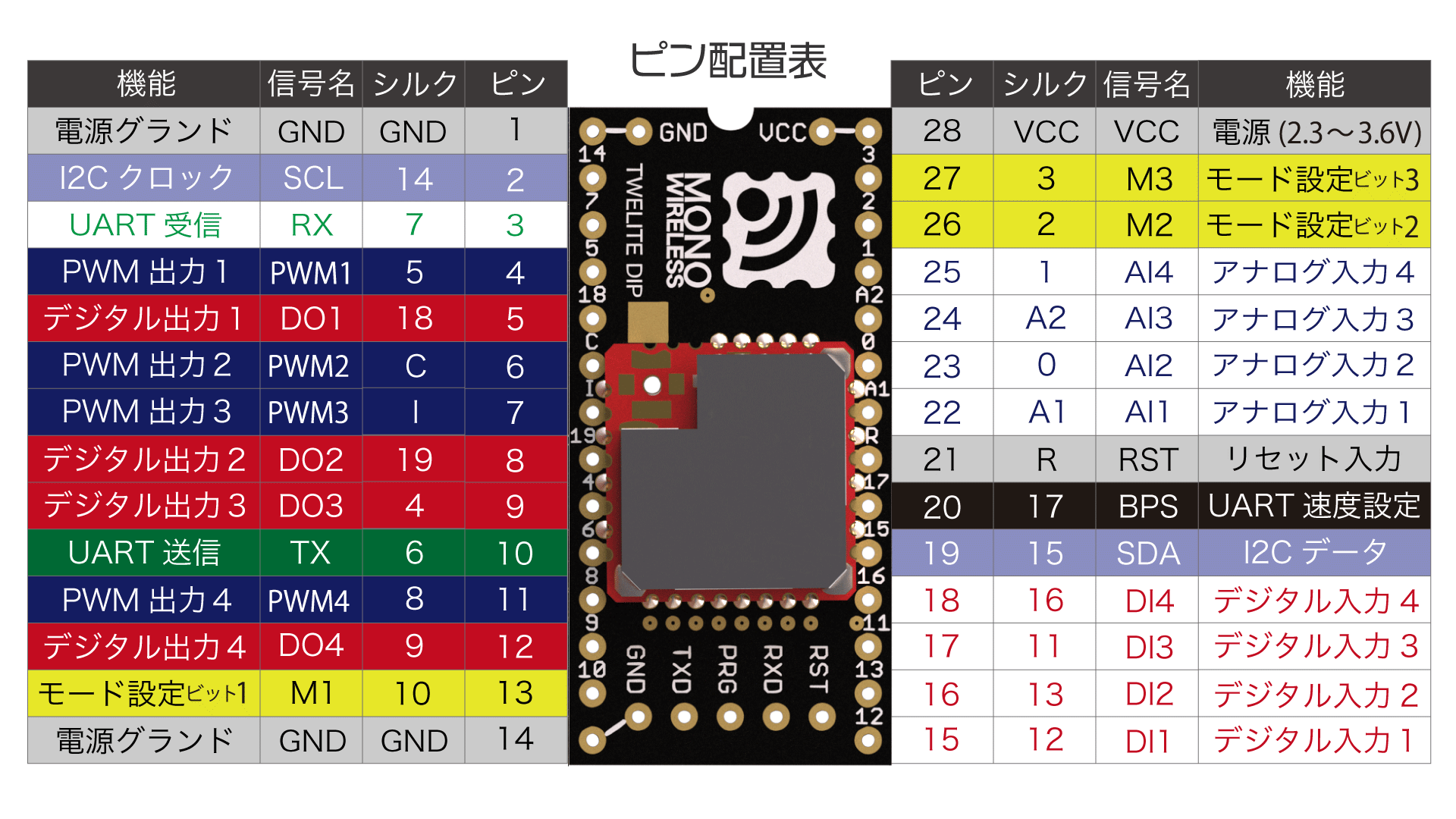
TWELITE / TWELITE DIP
The functions of pins used by the Remote Control App are represented using the names from the diagram of Extremely Simple! Standard App Pins.
Sends input states to the parent device every 10 seconds, disables reception, and always enters power saving mode
✅
127
O: Not connected (OPEN), G: Connected to GND
Initial mode is Child: Continuous mode.
The initial Logical Device ID (LID) used to identify the device differs depending on the mode.
Only in parent or repeater modes, you can switch the LID in Interactive Mode.
Please set parent to 121 and repeater to 122.
Parent Device
Continuous Mode
Parent: Continuous Mode
When a change in signal input is detected, or every second, data is sent to all child devices.
It also always waits for data sent from child devices, so it responds quickly but continuously consumes power.
Reception: Always waiting
Transmission: On input change / every 1 second
Child Device
Continuous Mode
Child: Continuous Mode
When a change in signal input is detected, or every second, data is sent to all parent devices.
It also always waits for data sent from parent devices, so it responds quickly but continuously consumes power.
Image of communication with parent device
Reception: Always waiting
Transmission: On input change / every 1 second
Disable periodic transmission
You can disable periodic transmission every 1 second by setting option bit 0x00000020 in Interactive Mode.
Child: Continuous 0.03s Mode
This mode shortens the periodic transmission interval of Child: Continuous Mode from 1 second to 0.03 seconds.
Although it always waits for data sent from the parent device, it occupies the bandwidth of communication from child to parent, causing slower response to parent input. It continuously consumes power.
Image of communication with parent device
Reception: Always waiting
Transmission: On input change / every 0.03 seconds
Since a single child device occupies most of the bandwidth, avoid using multiple child devices simultaneously if possible.
Intermittent Mode
Child: Intermittent 1s Mode
When a change in signal input is detected, or every second, the power saving mode is disabled and data is sent to all parent devices.
Reception is disabled, so it cannot be controlled by the parent device. This mode has excellent power saving performance.
Image of communication with parent device
Reception: Disabled
Transmission: On input change / every 1 second
Child: Intermittent 10s Mode
When a change in signal input is detected, or every 10 seconds, the power saving mode is disabled and data is sent to all parent devices.
Reception is disabled, so it cannot be controlled by the parent device. This mode has excellent power saving performance.
Image of communication with parent device
Reception: Disabled
Transmission: On input change / every 10 seconds
Repeater Device
Continuous Mode
Repeater: Continuous Mode
The repeater transmits received packets.
You can install up to three repeaters between parent and child devices, but increasing repeaters increases the number of packets, which can cause interference.
Image of relay
Reception: Always waiting
Transmission: On reception
4.1.3 - Remote Control App Alternative Baud Rate Setting
Changing the baud rate used for UART communication
The Remote Control App (App_IO) uses 115200 bps as the default baud rate for UART communication, but this can be changed.
Enabling Alternative Baud Rate Setting
You can enable the alternative baud rate setting by connecting the BPS pin to GND.
The baud rate setting in Interactive Mode indicates the alternative baud rate. If the BPS pin is not connected to GND, the Interactive Mode setting value will not be applied.
Interactive Mode uses UART communication. When switching the baud rate of TWELITE, you must adjust the PC side baud rate before using Interactive Mode (TWELITE STAGE App Settings).
4.1.4 - Remote Control App UART Function
Data format used for UART function.
Explanation of data format used in the UART function of Remote Control App (App_IO).
Digital Input and Output
0x81: Status Notification from the Remote Device
Outputs the state of the received input signal.
Data Format
#
Data
Description
Remarks
char
Header
: only
0
uint8
Source Logical Device ID
1
uint8
Command Number
0x81 only
2
uint8
Packet Identifier
0x0F only
3
uint8
Protocol Version
0x01 only
4
uint8
LQI
0-255
5
uint32
Source Serial ID
0x8???????
9
uint8
Destination Logical Device ID
10
uint16
Timestamp
64 counts per second, MSB is internal flag
12
uint8
Relay Count
13
uint16
Digital Signal
Corresponds to Ix from LSB, 0 is High
15
uint16
Digital Signal Mask
Corresponds to Ix from LSB, 1 means valid
17
uint16
Digital Signal Flag
Corresponds to Ix from LSB, 1 means interrupt
19
uint8
Unused
For internal management
uint8
Checksum
LRC8
char
Footer
CR (0x0D/'\r')
char
Footer
LF (0x0A/'\n')
Example Output Data
:01810F01DB8630000200645F000040004F00400049
Interpretation of the Above Data
#
Data
Description
Value
:
char
Header
:
01
0
uint8
Source Logical Device ID
0x78
81
1
uint8
Command Number
0x81
0F
2
uint8
Packet Identifier
0x15
01
3
uint8
Protocol Version
0x01
DB
4
uint8
LQI
219/255
86300002
5
uint32
Source Serial ID
0x6300002
00
9
uint8
Destination Logical Device ID
0x00
645F
10
uint16
Timestamp
Approx. 401 seconds
00
12
uint8
Relay Count
0
0040
13
uint16
Digital Signal
I7 is Low
004F
15
uint16
Digital Signal Mask
I7,I1-I4 are valid
0040
17
uint16
Digital Signal Flag
I7 changed due to interrupt
00
19
uint8
Unused
49
uint8
Checksum
0x49
char
Footer
\r
char
Footer
\n
0x80: Remote Device Output Change
Controls the output signals of the remote device.
Data Format
#
Data
Description
Remarks
char
Header
: only
0
uint8
Destination Logical Device ID
Parent 0x00, Child 0x01-0x64, All Children 0x78
1
uint8
Command Number
0x80 only
2
uint8
Format Version
0x01 only
3
uint16
Digital Signal
Corresponds to Ox from LSB, 0 is High
5
uint16
Digital Signal Mask
Corresponds to Ox from LSB, 1 is valid
7
uint16
Unused
0
9
uint16
Unused
0
11
uint16
Unused
0
13
uint16
Unused
0
uint8
Checksum
LRC8
char
Footer
CR (0x0D/'\r')
char
Footer
LF (0x0A/'\n')
Parent and repeater apps (v1.2 and earlier) do not support this format.
There is a reported bug with TWELITE GOLD App_IO v1.3.2 where transmission commands may not work in some cases.
The cause is under investigation. For TWELITE STICK, please use App_Wings v1.3.2 (TWELITE Apps unified version is also available).
Usually, enter Interactive Mode with screen, then after pressing Ctrl+A, execute :exec !! lrx -b -X /path/to/conf.bin
If the download succeeds, it generates a 128-byte file (may be smaller depending on the xmodem implementation).
3. Creating Custom Binary
Concatenate the downloaded file to the end of the firmware binary file to create a custom binary.
Use command line tools or general file concatenation tools for concatenation.
Example
An example when the downloaded xmodem file is conf.bin, the original binary file is App_IO_BLUE_L1305_V1-3-X.bin, and the custom binary to be created is App_IO_custom_V1-3-X.bin.
【Windows】
copy App_IO_BLUE_L1305_V1-3-X.bin App_IO_custom_V1-3-X.bin
type conf.bin >> App_IO_custom_V1-3-X.bin
Create a group by generating an application ID based on the parent’s serial ID and feeding it to the child devices. Connect an LED to the LED pin to check if the configuration is successful.
Connection
Connect an LED and a current limiting resistor (680Ω) to the LED pins of the parent and child devices (with correct polarity).
Leave M1 open and connect M2 and M3 to GND.
Power on the parent device and check that the LED blinks.
Within 5 seconds, power on the child device near the parent and confirm that the LED turns off (if it stays lit, the configuration failed).
4.1.7 - Interactive Mode (Remote Control App)
Configuration changes via Interactive Mode
You can perform detailed settings of the app via Interactive Mode.
This section explains features specific to the Remote Control App (App_IO). For common features, please refer to the TWELITE APPS Manual Top Page.
Interactive Mode cannot be used while TWELITE is sleeping.
Please ensure that the M3 pin is not connected to GND.
Display Example
The screen below will be displayed.
--- CONFIG/APP_IO V1-03-2/SID=0x86300001/LID=0x00 ---
 a: set Application ID (0x67720107)
 i: set Device ID (--)
 c: set Channels (16)
 x: set Tx Power (3)
 t: set mode4 sleep dur (1000ms)
 y: set mode7 sleep dur (0s)
 f: set mode3 fps (16)
 d: set hold mask (000000000000)
 D: set hold dur (1000ms)
 o: set Option Bits (0x00000000)
 b: set UART baud (38400)
 p: set UART parity (N)
 C: set crypt mode (0)
 K: set crypt key []
---
 S: save Configuration
 R: reset to Defaults
Set this when it is necessary to distinguish multiple child devices.
If distinction is not necessary or not possible, set to 120. If distinction is necessary, child devices should be any value from 1 to 100, and parent device should be 0 or 121.
Overwrite the intermittent interval of the child device intermittent 10-second mode from 10 seconds to another value. Unit is seconds.
If 0 is set, periodic wake-up by timer is disabled. In this case, the device wakes up on the falling edge of Ix, but not on the rising edge.
f: Child Device Continuous 0.03-Second Mode Cycle
Overwrite the number of transmission requests per second from 32 times to 4/8/16 times. Retry count is not included.
d: Hold/Long Press Mode Targets
By default, select ports targeted by hold mode, and when Option Bit 0x00000100 is enabled, select ports targeted by remote control long press mode.
Specify the bitmask of Ix or Ox ports to target. The value consists of up to 12 characters of 0 or 1. From LSB, the order is I1I2 … I12.
For example, specifying 000000001010 applies hold mode to I2 and I4. If any pin is targeted, ports not targeted output a 50ms pulse.
Hold Mode
In hold mode, targeted ports behave as follows:
Input (Transmission) side: Ix
After all inputs return from Lo to Hi, continuous transmission occurs for the configured duration (to release hold).
Output (Reception) side: Ox
For received inputs that are Lo, output holds Lo for the configured duration.
If during hold of any output, another Lo signal is received, the hold duration is extended.
Remote Control Long Press Mode
In remote control long press mode, targeted ports behave as follows:
Input (Transmission) side: Ix
Continuous transmission while any input is Lo.
After all inputs return from Lo to Hi, continuous transmission occurs for the configured duration.
Output (Reception) side: Ox
After packets with any input Lo are interrupted, outputs return Hi after the configured duration.
D: Hold/Long Press Mode Duration
By default, specify hold mode duration; when Option Bit 0x00000100 is enabled, specify hold duration or transmission interval for remote control long press mode.
Specify a value between 20 and 64000 ms.
Hold Mode
For hold mode, the configured duration applies as follows:
Input (Transmission) side: Ix
In continuous mode, the duration of continuous transmission after all inputs return from Lo to Hi.
In intermittent mode, the transmission interval while any input is Lo.
Output (Reception) side: Ox
The duration to maintain output.
Remote Control Long Press Mode
For remote control long press mode, the configured duration applies as follows:
Input (Transmission) side: Ix
The duration of continuous transmission after all inputs return from Lo to Hi.
Output (Reception) side: Ox
The time from interruption of packets with any input Lo until all outputs return to Hi.
o: Option Bits
Specify a 32bit number. Enable settings associated with each bit.
Overwrite the alternative baud rate selected when starting with the BPS pin connected to GND from 38400 bps.
Values can be selected from 9600/19200/38400/57600/115200/230400. Other values may cause errors.
If the BPS pin is left open at startup, this setting will not apply and will be fixed at 115200 bps.
p: UART Parity
Set to N (None), O (Odd), or E (Even). Stop bit is fixed to 1, hardware flow control is not supported.
C: Encryption
Specify whether encryption is enabled.
Set 1 to enable AES128bit encryption.
K: Encryption Key
Input the key used for encryption. Specify a 16-character text (binary sequences cannot be specified).
Details of Option Bits
Explanation of settings associated with each bit of the option bits value.
0x00000001: Low Latency Mode
Monitor input status and perform wireless transmission in low latency mode.
Shortens button monitoring time and minimizes transmission delay. In continuous mode, interrupts are used for input judgment but are more susceptible to chattering. In intermittent mode, reduces time to confirm input status.
Only valid for child devices.
0x00000002: Low Latency Mode (Sleep Interrupt)
When waking from sleep due to an interrupt from Ix going from Hi to Lo in intermittent mode, quickly send port information of the interrupt source.
Especially used in child device intermittent 10-second mode when periodic wake-up is disabled, combined with hold mode to detect button presses.
To install the Serial Communication App (App_Uart), install the TWELITE STAGE SDK and rewrite using the TWELITE STAGE App.
5.1.1 - Pin Assignments of Serial Communication App
Functions of pins used by the Serial Communication App
The following information applies to App_Uart v1.2 and later.
Unused pins should be left open.
TWELITE / TWELITE DIP
The functions of pins used by the Serial Communication App are represented using the pin names from the Super Simple! Standard App Pins shown in the figure below.
Connect a 3.3V (2.0-3.6V) power supply to VCC/GND.
Serial Input and Output
TX/RX are used for transmitting and receiving serial communication (UART).
Since the level is 3.3V, when connecting to microcontrollers operating at 5V levels such as Arduino, please perform level conversion.
Serial Sub Input and Output
TX_SUB (SCL) / RX_SUB (SDA) can be used as sub-ports for serial input and output.
Serial Input Permission
When RTS (PWM1) is at Low level, it indicates that serial input to RX is being accepted.
By suppressing input to RX when at High level, it is expected to prevent data loss.
Parent/Child Selection
Connecting M1 to GND sets the device as a parent, while leaving it open or connecting to VCC sets it as a child.
Setting via Interactive Mode
You can omit this connection and configure it via the interactive mode.
i set Device ID: 0
Adding Relay Function to Child
When M2 is connected to GND in child mode, relay functionality can be added.
Setting via Interactive Mode
You can omit this connection and configure it via the interactive mode.
r set Role: 1 or 0x12
Sleep
Connecting M3 to GND puts the device into sleep mode.
Overwriting Operation Mode
By connecting EX1 to GND at startup, the operation mode can be overwritten to format mode (binary).
Enabling Alternative Baud Rate Setting
Connecting BPS to GND enables the alternative baud rate setting specified in interactive mode.
Reset Input
By connecting a push button between RST and GND, a reset button can be implemented. RST has an internal pull-up resistor.
Enter interactive mode
By connection SET to GND on startup, the interactive mode will be ready.
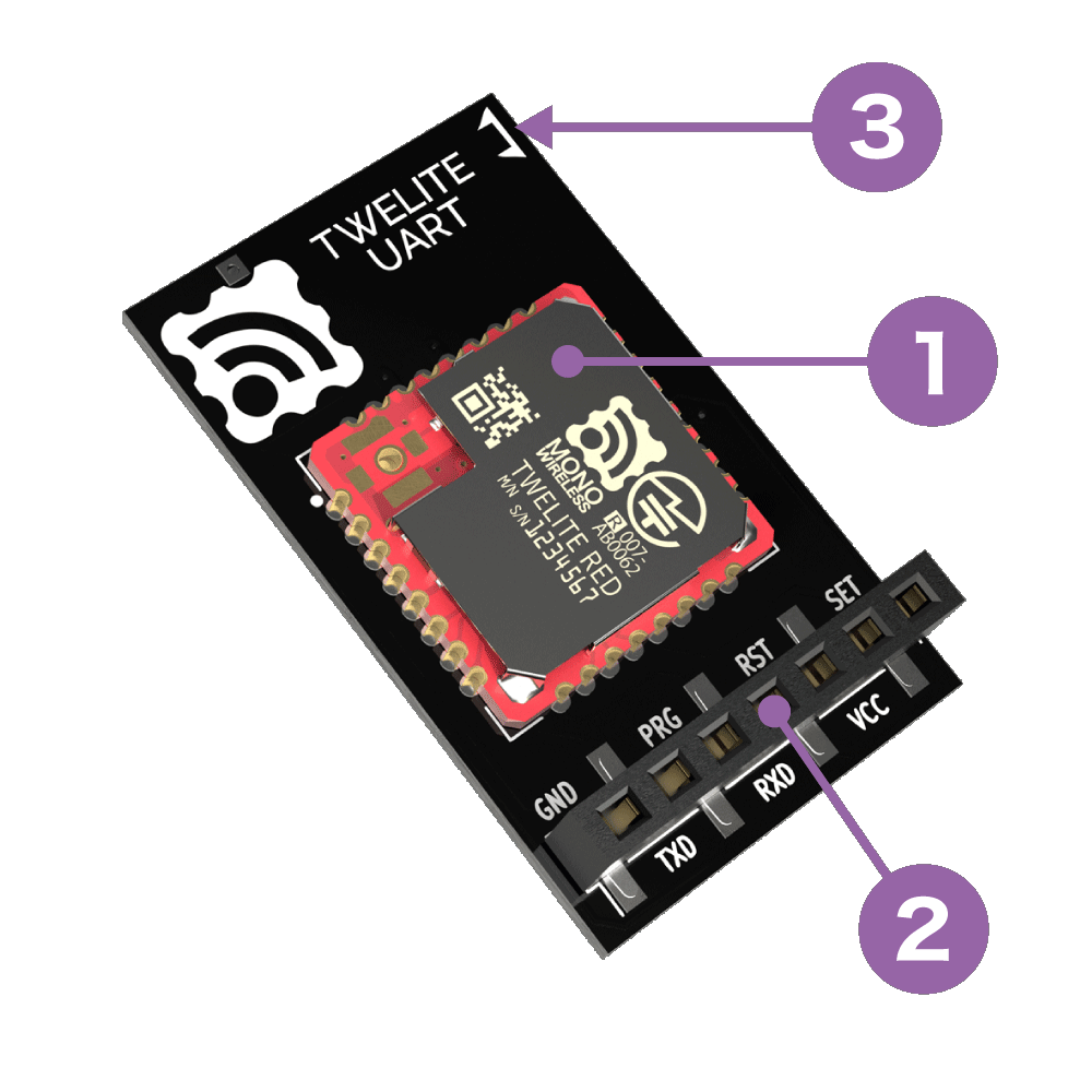
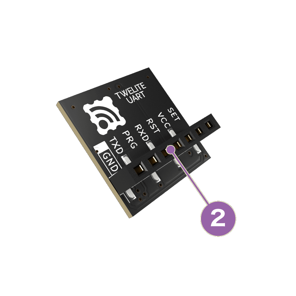
TWELITE UART
The functions of pins used by the Serial Communication App are represented using the pin names of the 7P interface printed on the board (② in the figure below).
Regardless of mode, please keep transmitted data within 80 bytes
Due to packet size constraints, please keep the data sent at one time within 80 bytes in binary.
The maximum length of packets in IEEE 802.15.4 adopted by TWELITE is 128 bytes, and considering overhead, the payload area available for the serial communication app is limited to 80 bytes.
If you need to send a large amount of data, please consider other products using Wi-Fi, etc. TWELITE is suitable for efficiently sending small amounts of data.
A: Format Mode (ASCII)
When data is input to the transmitting terminal according to a specific format, the receiving terminal outputs data according to the same specific format.
Data represented in hexadecimal is expressed as ASCII strings.
Input on Transmitting Side
Output on Receiving Side
Simple/Extended format data
→
Simple/Extended format data
In TWELITE UART, this mode is enabled when started with the SET pin connected to GND.
There are two formats to represent data.
Simple format: Uses only logical device ID. Super simple! Compatible with the standard app’s UART transmission function.
Extended format: Uses transmission options such as serial ID and retransmission count in addition to logical device ID.
For example, 5-byte binary data 0x48 0x45 0x4C 0x4C 0x4F can be sent using the simple format as follows.
[Transmitting Side]
:000148454C4C4F8B  <- Input
:DBA1800103  <- Output
[Receiving Side]
:780148454C4C4F13 <- Output
In format mode, settings such as application ID can be dynamically applied not only by Interactive Mode but also by commands via UART (ASCII format).
When data is input to the transmitting terminal according to a specific format, the receiving terminal outputs data according to the same specific format.
Data represented in hexadecimal is expressed in binary format as is.
Input on Transmitting Side
Output on Receiving Side
Simple/Extended format data
→
Simple/Extended format data
In TWELITE / TWELITE DIP, this mode is enabled when started with the EX1 pin connected to GND.
Like Format Mode (ASCII), there are two formats to represent data.
For example, 5-byte binary data 0x48 0x45 0x4C 0x4C 0x4F can be sent using the simple format as follows.
When arbitrary data is input to the transmitting terminal, the receiving terminal outputs the received content with auxiliary information added in a specific format.
Input on Transmitting Side
Output on Receiving Side
Any data
→
Any data + auxiliary information
By default, data input to the transmitting side is separated by CRLF, and data before CRLF is sent.
For example, when Hello<Enter> is input on the transmitting terminal, the receiving terminal outputs Hello in a format including auxiliary information. The transmitting terminal also outputs a format that conveys a transmission completion message.
The auxiliary information output by the receiving side includes the sender’s address, received signal strength, checksum, etc. The format of auxiliary information can be customized.
5.1.2.1 - Serial Communication App Format Mode (ASCII)
Mode that adds headers to both transmitted and received outputs (ASCII format)
Format mode adds headers to both transmitted and received outputs. In ASCII format, data is represented as hexadecimal strings.
Overview
When data formatted in a specific manner is input on the transmitting side, the receiving side outputs data formatted in the same manner.
Data is represented as hexadecimal ASCII strings.
Transmitting Side Input
Receiving Side Output
Simple/Extended format data
→
Simple/Extended format data
In TWELITE UART, format mode (ASCII) is enabled by starting up with the SET pin connected to GND.
In TWELITE / TWELITE DIP, format mode (binary) is enabled by starting up with the EX1 pin connected to GND.
There are two types of formats that can be handled.
Simple format: uses only the Logical Device ID. Extremely Simple! Compatible with the UART transmission function of the standard app.
Extended format: uses Logical Device ID plus transmission options such as Serial ID and retry count.
For example, 5-byte binary data 0x48 0x45 0x4C 0x4C 0x4F can be sent using the simple format as follows.
[Sending side]
:000148454C4C4F8B  <- Input
:DBA1800103  <- Output
[Receiving side]
:780148454C4C4F13 <- Output
Basic Format
When sending data sequences expressed in basic or extended formats, they are converted to ASCII strings (0-9, A-F).
The format is extremely simple! It starts with : and ends with CRLF, just like the output of the standard app (App_Twelite) or the parent device output of the parent/repeater app (App_Wings).
Header
Payload
Checksum
Footer
:
Repeated 00-FF
LRC8 of payload
CRLF
All ASCII characters
Starts with : (0x3A)
Checksum is the two’s complement of the sum of the payload
Ends with CRLF (\r\n/0x0D 0x0A)
Big-endian
For example, binary data 0x00 0x11 0x22 0x33 0xAA 0xBB 0xCC is expressed as follows.
:00112233AABBCC69<CR><LF>
Distinguishing Parent and Child Devices
Format mode distinguishes between parent and child devices.
If 1 second passes after input, the transmission process times out. Also, the internal buffer may become full with pending processes, and new requests cannot be accepted. When setting application retry or delay, be careful not to set extreme values.
0x01: Enable MAC ACK
Enables MAC layer ACK (acknowledgment).
Not suitable for frequent data transmission, but can improve reliability.
Not available for repeaters. Also, cannot be used when the destination is all children (0x78).
0x02: Enable Application Retry
When using MAC ACK, specify 0x00-0x0F. Retries 0-16 times respectively until the transmission succeeds.
When not using MAC ACK, specify 0x81-0x8F. Always retries 1-16 times.
Response messages are output after all retries are completed.
0x03: Minimum Initial Transmission Delay
Specifies the minimum delay before the first transmission in milliseconds.
0x04: Maximum Initial Transmission Delay
Specifies the maximum delay before the first transmission in milliseconds.
0x05: Application Retry Interval
Specifies the retry interval in milliseconds when application retry is enabled.
0x06: Allow Parallel Requests
Allows parallel requests.
When allowed, the next request can be accepted without blocking until the current request completes.
For example, if three requests with a 0.5-second delay are input consecutively, normally they are processed sequentially at 0.5s, 1.0s, and 1.5s. When parallel requests are allowed, they are processed in no particular order after 0.5s. Note that it cannot be used when packet fragmentation is required.
The receiving device always adopts the newest data. When parallel requests are allowed, old data may arrive after new data and be ignored.
0x07: Disable Response Messages
Disables the response messages output when data is input on the transmitting side.
0x08: Sleep After Transmission
Immediately puts the device to sleep after transmission.
When RX detects a rising edge, it wakes up from sleep. Please input any 1 byte of data.
After waking up, UART initialization completes and input is accepted.
Receiving Side Output
#
Data
Description
Notes
char
Header
Only :
0
uint8
Source Logical Device ID
Parent 0x00, child 0x01-0x64, unset child 0x78
1
uint8
Command number
Only 0xA0
2
uint8
Response ID
Value specified by the sender
3
uint32
Source Extended Address
Serial ID with 0x8 added at the front
7
uint32
Destination Extended Address
0xFFFFFFFF if using Logical Device ID
11
uint8
LQI
Radio communication quality at reception
12
uint16
Length of following byte sequence
Number of bytes (M)
14
[uint8]
Arbitrary data
Byte sequence of length (M)
uint8
Checksum
LRC8
char
Footer
CR (0x0D/'\r')
char
Footer
LF (0x0A/'\n')
Transmitting Side Output (Response Message)
#
Data
Description
Notes
char
Header
Only :
0
uint8
Source Logical Device ID
Only 0xDB: indicates itself
1
uint8
Command number
Only 0xA1
2
uint8
Response ID
Value specified at input
3
uint8
Result
Success 1, failure 0
uint8
Checksum
LRC8
char
Footer
CR (0x0D/'\r')
char
Footer
LF (0x0A/'\n')
Example Usage
An example of sending byte sequence 0x11 0x22 0x33 0xAA 0xBB 0xCC from the parent to a child is shown.
Example specifying Logical Device ID
An example sending from the parent to the child with Logical Device ID 0x42.
Response ID is 0x01
No options
Parent’s extended address is 0x81000000 (Serial ID 0x1000000)
Set bits for channels to be used. For example, to use channel 11, specify 1<<11.
0x02: Retry Count and Output
Specifies the radio transmission output and the number of additional packet transmissions in transparent mode and header-attached transparent mode.
Only the lower 1 byte is used. The upper 4 bits represent the retry count (0-9), and the lower 4 bits represent the transmission output (0-3). For example, 8 retries / output 3 is 0x0083.
0x03: Logical Device ID
Specifies the logical device ID.
0x04: Role
Effective only for slave devices. Specify one of the following values. Normally, select a delivery method that does not use the network layer.
Delivery Methods Without Network Layer
0: Normal designation (parent or child device)
1-3: Relay slave devices (logical device IDs are 1-100 or 120). Numbers 1-3 indicate the maximum relay hop count. This method retransmits up to the maximum relay hops, which may cause duplicate packets depending on relay device placement and count.
Delivery Methods Using Network Layer
11: Parent device
12: Relay device
13: Child device
To enable silent mode, add 80 to the above values. For example, 93 means “network layer enabled and silent mode”.
0x05: Relay Layer
The relay layer number. Relay devices attempt to connect to relay devices or parent devices in upper (smaller value) relay layers. Effective only when Role is set to 12.
0x06: Communication Mode
0: Transparent mode
1: Format mode (ASCII)
2: Format mode (Binary)
3: Chat mode
4: Header-attached transparent mode
0x07: Baud Rate
Specifies the UART baud rate.
0x08: Parity
Specifies the sum of settings in the following combination:
Bit
0: 8Bit
8: 7Bit
Parity
0: None
1: Odd
2: Even
Stop
0: STOP 1
4: STOP 2
For example, 7-E-1 is specified as 8+2+0=10(0xA).
0x09: Encryption Function
Specifies whether encryption is enabled.
0: Disabled
1: AES128bit encryption enabled
0x0A: Encryption Key
Specifies a 16-byte encryption key.
Can store binary sequences that cannot be set in Interactive Mode. This may cause display issues in Interactive Mode.
0x0B: Header / Handle name
Specifies a header format on the mode E or handle name on the mode C.
0x0C: Delimiter Character
Specifies the delimiter character (0x00-0xFF).
5.1.2.2 - Serial Communication App Format Mode (Binary)
Mode that adds headers to both transmitted and received outputs (binary format)
Format mode adds headers to both transmitted and received outputs. In binary format, data is represented as raw binary.
Overview
When data formatted in a specific manner is input on the transmitting side, the receiving side outputs data formatted in the same manner.
Data represented in hexadecimal is output as raw binary.
Transmitting Side Input
Receiving Side Output
Simple/Extended Format Data
→
Simple/Extended Format Data
On TWELITE UART, format mode (ASCII) is enabled by connecting the SET pin to GND at startup.
On TWELITE / TWELITE DIP, format mode (binary) is enabled by connecting the EX1 pin to GND at startup.
There are two types of supported formats.
Simple format: uses Logical Device ID only; Extremely Simple! Compatible with UART transmission function of the standard app
Extended format: uses Logical Device ID plus options such as Serial ID and retry count
For example, 5 bytes of binary data 0x48 0x45 0x4C 0x4C 0x4F can be transmitted using the simple format as follows.
Hereafter, the 0x in binary data representation is omitted.
For example, 0x48 0x45 0x4C 0x4C 0x4F is represented as 48 45 4C 4C 4F.
If 1 second passes after input, the transmission process times out. Also, if the internal buffer becomes full with pending processes, new requests may not be accepted. When setting application retransmission or delay, avoid extreme values.
0x01: Enable MAC ACK
Enables MAC layer ACK (acknowledgment).
Not suitable for frequent data transmissions but can improve reliability.
Relay devices cannot use this. Also, it cannot be used when the destination is all children (0x78).
0x02: Enable Application Retransmission
When using MAC ACK, specify 0x00-0x0F. Retransmits 0-16 times until successful.
When not using MAC ACK, specify 0x81-0x8F. Always retransmits 1-16 times.
Response messages are output after all retransmissions are complete.
0x03: Minimum Initial Transmission Delay
Specifies the minimum delay before the first transmission in milliseconds.
0x04: Maximum Initial Transmission Delay
Specifies the maximum delay before the first transmission in milliseconds.
0x05: Application Retransmission Interval
Specifies the interval between application retransmissions in milliseconds.
0x06: Allow Parallel Requests
Allows parallel requests.
When allowed, the next request can be accepted without blocking until the previous request completes.
For example, if three requests each with 0.5 seconds delay are input consecutively, normally they are processed sequentially at 0.5s, 1.0s, and 1.5s. With parallel requests allowed, they are processed in any order after 0.5s. Note that this cannot be used when packet segmentation is required.
Receiving devices always adopt the newest data. When parallel requests are allowed, older data may arrive after newer data and be ignored.
0x07: Disable Response Messages
Disables response messages output when data is input on the transmitting side.
0x08: Sleep After Transmission
Immediately puts the device to sleep after transmission.
RX detects rising edge to wake from sleep. Input any 1 byte of data.
After waking, UART initialization completes and input is accepted.
Receiving Side Output
#
Data
Description
Notes
uint8
Header
Only 0xA5
uint8
Header
Only 0x5A
uint16
Data Length
\(M\)+14
0
uint8
Source Logical Device ID
Parent 0x00, Child 0x01-0x64, Unset Child 0x78
1
uint8
Command Number
Only 0xA0
2
uint8
Response ID
Value specified by sender
3
uint32
Source Extended Address
Serial ID with 0x8 added at the front
7
uint32
Destination Extended Address
0xFFFFFFFF when using Logical Device ID
11
uint8
LQI
Radio signal quality at reception
12
uint16
Length of Following Bytes
Byte count \(M\)
14
[uint8]
Arbitrary Data
Byte sequence of length \(M\)
uint8
Checksum
XOR
uint8
Footer
EOT (0x04)
Transmitting Side Output (Response Message)
#
Data
Description
Notes
uint8
Header
Only 0xA5
uint8
Header
Only 0x5A
uint16
Data Length
4
0
uint8
Source Logical Device ID
Only 0xDB: indicates itself
1
uint8
Command Number
Only 0xA1
2
uint8
Response ID
Value specified on input
3
uint8
Result
Success 1, Failure 0
uint8
Checksum
XOR
uint8
Footer
EOT (0x04)
Examples
Example of sending byte sequence 11 22 33 AA BB CC from parent to child.
Example specifying Logical Device ID
Example of sending from parent to child with Logical Device ID 0x01.
Response ID is 0x01
No options
[Transmitting Side: Parent]
A5 5A 80 0A 01 A0 01 FF 11 22 33 AA BB CC 82 04  <- Input
A5 5A 80 04 DB A1 01 01 7A 04  <- Output
The last byte 0xC1 is checksum: XOR from 0x42 to 0xCC.
Set bits for channels to use. For example, to use channel 11, set 1<<11.
0x02: Retry Count and Output
Specifies the radio transmission output and the number of additional packets to send in transparent mode and header-attached transparent mode.
Only the lower 1 byte is used. The upper 4 bits indicate retry count (0-9), and the lower 4 bits indicate transmission output (0-3). For example, 8 retries/output 3 is 0x0083.
0x03: Logical Device ID
Specifies the logical device ID.
0x04: Role
Valid only for child devices. Specify the following values. Usually, select a delivery method without using the network layer.
Delivery Methods Without Using Network Layer
0: Normal designation (parent or child)
1-3: Relay child devices (logical device IDs 1-100 or 120). Numbers 1-3 indicate maximum relay hops. This method repeats retries up to the maximum relay hops, which may cause duplicate packets depending on relay device placement and number.
Delivery Methods Using Network Layer
11: Parent device
12: Relay device
13: Child device
To enable silent mode, add 80 to the above values. For example, 93 means “using network layer and silent mode”.
0x05: Relay Layer
The relay layer number. Relay devices attempt to connect to relay devices or parent devices with higher layers (lower values). Effective only when Role is set to 12.
0x06: Communication Mode
0: Transparent mode
1: Format mode (binary)
2: Format mode (binary)
3: Chat mode
4: Header-attached transparent mode
0x07: Baud Rate
Specifies UART baud rate.
0x08: Parity
Specifies the sum of settings in the following combination.
Bit
0: 8Bit
8: 7Bit
Parity
0: None
1: Odd
2: Even
Stop
0: STOP 1
4: STOP 2
For example, 7-E-1 is 8+2+0=10(0xA).
0x09: Encryption Function
Specifies whether encryption is enabled.
0: Disabled
1: AES128bit encryption enabled
0x0A: Encryption Key
Specifies a 16-byte encryption key.
Allows storing binary sequences that cannot be set in Interactive Mode. In this case, the display in Interactive Mode may be disrupted.
0x0B: Header / Handle name
Specifies a header format on the mode E or handle name on the mode C.
0x0C: Delimiter Character
Specifies the delimiter character string (0x00-0xFF).
5.1.2.3 - Serial Communication App Chat Mode
Mode that displays prompts and performs echo back
Chat mode realizes text chat through prompt display and echo back.
By connecting MONOSTICK to a PC etc., chat can be performed among multiple terminals.
Overview
Enables text chat.
Sending Side Input
Receiving Side Output
Any string
→
Any string + auxiliary information
Displays prompt and echoes back (outputs input characters). All terminals operate as child devices, performing broadcast communication.
For example, when sending the string Hello from one terminal to another, it behaves as follows.
Chat mode displays prompt and echoes back (outputs input characters entered by itself).
All terminals are treated as child devices and broadcast their transmitted content. Communication is possible with all terminals but destination cannot be specified. Binary data cannot be sent. Only strings are supported (0x00-0x1F, 0x7F cannot be sent).
Relay supports up to 3 hops. Relay is disabled by default.
Distinction between Parent and Child Devices
Chat mode does not distinguish between parent and child devices.
If the Application ID and frequency channel are the same, data entered in any terminal is sent to other terminals.
Network configuration image
Identification of Source
The auxiliary information in the received output can identify the sender.
If the Interactive Mode’s h: Header format is blank, the 7-digit serial ID with a leading 0x8 is used as the extended address. For example, the following output indicates the sender’s serial ID was 0x10A4778.
[810A4778:0] Hello
If h: Header format is set to an arbitrary string, it is used as the handle name. Handle name consumes data space in the wireless packet.
Sending Side Input Format
Enter message and newline after prompt.
Data
Content
Remarks
[char]
Message
0x00-0x1F, 0x7F not allowed
char
CR (0x0D/'\r')
Allowed alone
char
LF (0x0A/'\n')
Allowed alone
810A4778:0> Hello
Receiving Side Output Format
Outputs received message following auxiliary info.
Auxiliary information includes the module’s extended address or handle name and a sequence number.
Data
Content
Remarks
char
Auxiliary info header
[ only
[char]
Identification info
8-digit extended address or handle name
char
Auxiliary info delimiter
: only
[char]
Sequence number
Starting from 0
char
Auxiliary info footer
] only
char
Separator
Space only
[char]
Message
char
Footer
CR (0x0D/'\r')
char
Footer
LF (0x0A/'\n')
In case of errors etc., messages enclosed in parentheses like (err) or (canceled) are output.
[810A4778:0] Hello
Other Inputs
Terminals supporting escape sequences can use the following control commands.
Ctrl-L: Clear screen
Ctrl-C: Cancel input
BS/DEL: Move cursor back
5.1.2.4 - Serial Communication App Transparent Mode
Mode that purely wirelesss UART
Transparent mode realizes behavior similar to UART connected by wires without adding headers, echo back, or prompt display.
External microcontrollers can be easily connected, but to optimize communication using formats, format modes (ASCII / Binary) are suitable.
Overview
Purely wirelesss UART.
Sending side input
Receiving side output
Any data
→
Any data
Since no format is required, existing UART communication can be easily wirelessized.
However, data delimiters are ambiguous and it is impossible to identify the sender from the receiver output.
The initial state specifies CRLF as the transmission trigger character. Therefore, data input to the transmitter is separated by CRLF, and the data before CRLF is transmitted.
For example, entering Hello<Enter> on the transmitting terminal results in Hello being output on the receiving terminal.
[Sending side]
Hello <- Input
[Receiving side]
Hello <- Output
Continuous input strings are split and sent in chunks of 80 bytes. Data up to the trigger character should normally be 80 bytes or less.
All terminals are considered child devices, and the transmitted content is broadcast. Communication with all terminals is possible, but the destination cannot be specified. Both ASCII characters and binary data can be sent.
Relay supports up to 3 hops. By default, relay is disabled.
Distinction between Parent and Child Devices
Transparent mode does not distinguish between parent and child devices.
If application ID and frequency channel are the same, data entered into any terminal is sent to other terminals.
Network configuration image
Identification of Sender
Transparent mode cannot identify the sender.
To identify sender, sender information must be included in data input to the transmitter.
Transmission Trigger
Transmission trigger must be considered, as data is divided and transmitted wirelessly packet by packet.
Therefore, the following transmission triggers must be taken into account:
When a timeout after data input is reached
When the input data reaches the minimum data size
When the transmission trigger character is received
Transmission Trigger Priority
When timeout is reached, transmission is forced. Also, if a minimum data size is set, the transmission trigger character is invalid unless that size is met.
Transmission trigger settings can be specified from the interactive mode k: Transmission Trigger item.
Example Setting
When setting the transmission trigger character to LF, minimum data size to 8 bytes, and timeout to 30 ms, set as follows:
 m: set UART mode (D)
 k: set Tx Trigger (sep=0x0a, min_bytes=8 dly=30[ms])
 o: set option bits (0x00000100)
5.1.2.5 - Serial Communication App Header Transparent Mode
Mode that adds headers only to the received output
Header Transparent Mode adds auxiliary information only to the output on the receiving side.
Overview
Enabled by default.
When arbitrary data is input to the transmitting terminal, the receiving terminal outputs data with auxiliary information in a specific format.
Transmitting side input
Receiving side output
Any data
→
Any data + auxiliary info
By default, data input on the transmitting side is separated by CRLF and data before CRLF is sent.
For example, entering Hello<Enter> on the transmitting side results in output Hello with auxiliary info on the receiving side. The transmitting side also outputs a message indicating transmission completion.
The auxiliary information output by the receiving side includes the source address, received signal strength, checksum, etc. The format of the auxiliary information can be customized.
Distinction between Parent and Child Devices
Header Transparent Mode does not distinguish between parent and child devices.
The source logical device ID is 219 for its own response message.
The extended address is the 7-bit serial ID printed on the TWELITE device with a leading 0x8 added.
Customization by Header Format
The output format on the receiving side follows the header format.
Changing the header format customizes the content of the auxiliary information output and the checksum calculation range.
The default header format is ;U;%t;%i;0x%A;%q;%s;<*;%X;\n.
The header format can be changed via the interactive mode command h: set header format.
Simplest Format
The simplest header format is *\n. It outputs the received data with CRLF line endings.
h: set header format [*\n]
When sending HELLO in this case, it behaves as follows.
[Receiving side]
HELLO<CR><LF> or HELLO<LF>
[Transmitting side]
HELLO<CR><LF>
Special Characters in Header Format
You can customize the output by including the following special characters in the header format.
General
Description
*
Received data
&hl
Arbitrary ASCII character (e.g., &20 is space)
<
Start position for checksum calculation (default is start of string)
>
End position for checksum calculation (only from v1.4.6)
Characters following \ (backslash)
Description
\n
CRLF (0x0D0x0A)
\t
TAB
\*
*
\%
%
\<
<
\>
>
\&
&
Characters following %
Description
Length
Data format
%A
Source address (32bit)
8 chars
Hexadecimal
%a
Source address (32bit)
10 chars
Hexadecimal
%I
Source logical address (8bit)
2 chars
Hexadecimal
%i
Source logical address (8bit)
3 chars
Decimal
%T
Current system time (seconds)
4 chars
Hexadecimal
%t
Current system time (seconds)
5 chars
Decimal
%S
Source sequence number (hex)
2 chars
Hexadecimal
%s
Source sequence number (hex)
3 chars
Hexadecimal
%Q
Received signal strength
2 chars
Hexadecimal
%q
Received signal strength
3 chars
Decimal
%X
Checksum
2 chars
Hexadecimal
%x
Checksum
3 chars
Decimal
Checksum Calculation
The checksum is calculated by XOR (exclusive OR) from the start of the data or from the position indicated by < in the header format up to just before %X or %x.
Example in Default State
The default header format is ;U;%t;%i;0x%A;%q;%s;<*;%X;\n, where the checksum calculation range is *;.
That is, when sending HELLO, the binary data HELLO; is targeted, resulting in checksum 0x79.
[Verification code in Python]
from functools import reduce
defmain():
data ="HELLO;" checksum = reduce(lambda x, y: x ^ y, data.encode("ascii"))
print(f"{data} -> {hex(checksum)}")
if __name__ =="__main__":
main() # HELLO; -> 0x79
Other Examples
For example, consider the header format ;%I;*;%X.
Since < is not specified, the checksum calculation range is ;%I;*;.
That is, when sending HELLO, the binary data ;000;HELLO; is targeted, resulting in checksum 0x49.
[Verification code in Python]
from functools import reduce
defmain():
data =";000;HELLO;" checksum = reduce(lambda x, y: x ^ y, data.encode("ascii"))
print(f"{data} -> {hex(checksum)}")
if __name__ =="__main__":
main() # ;000;HELLO; -> 0x49
Transmission Trigger
There is no format on the transmitting side input, but data is split and transmitted packet by packet.
Therefore, the following transmission triggers must be considered.
When timeout after data input occurs
When input data reaches the minimum data size
When a transmission trigger character is received
Priority of Transmission Triggers
When timeout occurs, transmission is forced. Also, if a minimum data size is set, the transmission trigger character is invalid unless that size is reached.
Set this value if it is necessary to distinguish between multiple child devices.
If no distinction is needed or possible, set it to 120. If distinction is required, use any value between 1 and 100 for child devices, and use 121 for parent devices.
Valid for child devices only. Select one of the following. Normally, use a transmission mode that does not rely on the network layer (LayerTree).
Transmission Modes Not Using the Network Layer
0: Default (Parent or Child)
1–3: Repeater Child (set Logical Device ID to 1–100 or 120). The value indicates the maximum number of relay hops. Duplicated packets may occur depending on placement and number of repeaters.
Transmission Modes Using the Network Layer
Only supported in Header Transmission Mode.
11: Parent
12: Repeater
13: Child
l: LayerTree Relay Layer
Specifies the relay layer number. A repeater attempts to connect to parent or repeater devices with higher relay layers (smaller values). Valid only when Role is set to 12.
m: Communication Mode
A: Format Mode (ASCII)
B: Format Mode (Binary)
C: Chat Mode
D: Transparent Mode
E: Header Transmission Mode
t: TX Trigger Characters
In Transparent and Header Transmission modes, entering these characters triggers transmission of a packet.
If Minimum Data Size is specified, the characters will be ignored until that size is reached.
This setting is applied when Option Bit 0x00000100 (enabled by default) is set.
Initially, CRLF is used as the trigger.
u: Minimum Data Size
Specifies the minimum size of data to be handled continuously. TX Trigger Characters are ignored until this size is met.
In Interactive Mode, specify a number between 1–80 as byte count. Set to 0 to disable. The default is disabled.
T: Timeout
Time to wait from the last input before transmitting a packet.
In Interactive Mode, specify a value between 10–200 in milliseconds. Set to 0 to disable. The default is disabled.
This setting takes precedence over TX Trigger Characters and Minimum Data Size.
h: Header Format / Handle Name
Specifies the header format for Header Transmission Mode, or the handle name for Chat Mode.
Specify the handle name to display on the receiving device.
Up to 23 characters. This consumes part of the data transmission area (80 bytes).
C: Encryption
Specifies whether to enable encryption.
To enable AES128-bit encryption, set this to 1.
Devices with encryption enabled can receive plaintext messages, but cannot use Ack responses.
K: Encryption Key
Specify a 16-character encryption key when encryption is enabled.
Option Bits Details
This section describes each setting associated with the bits of the Option Bits value.
00000001: Disable Internal Pull-up of M3
Disables the internal pull-up resistor of the M3 pin used for sleep configuration on TWELITE DIP.
Do not boot in open state when the pull-up is disabled, as it may unintentionally enter sleep mode.
00000100: Enable TX Trigger
Enables the TX Trigger setting in Transparent or Header Transmission Mode.
This is enabled by default.
00000200: Prioritize New Input Stream
In Format Mode (ASCII/Binary), Transparent Mode, and Header Transmission Mode, if multiple input streams are received before the previous transmission is complete, the newer input is prioritized.
Useful when sending continuous control or measurement data to ensure the latest values are reflected.
00001000: Suppress Response Message
In Format Mode (ASCII/Binary) and Header Transmission Mode, suppresses the response message after transmission completes.
00004000: Relax Duplicate Checker
Relaxes the duplicate check conditions on the receiver side.
The duplicate checker prevents redundant packets that may arrive due to relays.
If the transmission interval is short (e.g., under 100 ms), even different packets might be mistakenly recognized as duplicates (even with different sequence numbers).
Enable this option when using short intervals or multiple transmitters concurrently.
Since Interactive Mode also uses UART, make sure to match the baud rate on the PC side when using Interactive Mode.
00020000: Simultaneous Output to Sub Port
Also outputs serial TX data to the secondary TX_SUB port.
The I/O buffer (4KB input, 4KB output) is split equally between the main and sub ports (2KB input, 2KB output each).
00040000: Switch Primary Port
Switches the serial I/O between the main TX/RX and the sub TX_SUB/RX_SUB ports.
About Repeater Function
When the communication range is insufficient or obstructed, using a repeater can be effective.
A repeater device retransmits packets it receives to other devices.
01000000: Disable LED
Disables the LED on TWELITE STICK and MONOSTICK.
02000000: Disable LED in Standby
Disables the LED on TWELITE STICK and MONOSTICK while in standby.
Configuring Repeater Function
Normally, enter Interactive Mode and change the Role to a value between 1 and 3. The default is 0, which does not enable the repeater function.
r: set Role (0x0)
The values 1 to 3 indicate the maximum number of relay hops. For example, setting it to 3 allows up to 3 hops.
This setting is only valid for child devices, not for parent devices.
Increasing the number of repeater hops or repeaters will also increase the number of packets transmitted. Communication within the same frequency channel may become unstable.
Example Configuration
The following network configuration shows an example where the Role of red devices is set to 0, and that of blue devices is set to 3.
Example of relaying via Role setting
By adding more red devices, communication with up to three relay hops between them can be established.
Example of adding transmitters and receivers
5.1.4 - Notes on Communication in Serial Communication App
Precautions for stable communication
Precautions for achieving stable communication.
UART Data Input and Output
4KB buffers are allocated for UART input and output. When outputting two UART lines, 2KB is used for input and output buffers for each line.
In format mode and chat mode, it is rarely necessary to be aware of buffer sizes, but in header transparent mode and transparent mode when continuously inputting streams, or even in format mode when inputting many streams at once, it is necessary to be aware of the buffer size limits. On the output side, if a slow baud rate is set, the output of data received wirelessly may not keep up.
Data beyond the buffer limits is not protected at the boundary, causing data loss. Especially on the input side, consider referring to the flow control pins described below.
UART Flow Control
Input flow control is implemented to behave like the RTS pin. The pin used is PWM1 (DIO5), targeting the main UART port. When input is not accepted, the state is High; when input is accepted, the state is Low. Output flow control is not supported. Receiving devices should ensure sufficient baud rate and processing speed.
After power-on or reset, the pin is High. It becomes Low once UART is initialized.
When the UART input buffer exceeds 7/8 full, the pin goes High; it goes Low when below that threshold.
In transparent mode, the pin is High during packet transmission.
Countermeasures for Wireless Communication Errors
If data loss occurs on the receiving side, increase the number of wireless retransmissions.
Increasing the number of additional packets sent can improve the success rate of reception.
The number of retransmissions can be set in Interactive Mode (x: set RF Conf).
5.1.5 - Custom Default Feature of Serial Communication App
Creating firmware with changed default settings
Only available on single versions of the App for BLUE / RED series.
With the custom default feature, you can change the default parameters included in the firmware.
For example, if you create firmware that changes the baud rate from 115200bps to 9600bps, you can use it at 9600bps from the start.
Usually, enter Interactive Mode with screen, then press Ctrl+A and execute :exec !! lrx -b -X /path/to/conf.bin
If the download succeeds, a 128-byte file is generated (may be smaller depending on xmodem implementation).
3. Creating Custom Binary
Concatenate the downloaded file to the end of the firmware binary file to create a custom binary.
Use command line tools or general file concatenation tools for concatenation.
Example
Example assuming downloaded xmodem file is conf.bin, original binary file is App_Uart_BLUE_L1305_V1-4-X.bin, and custom binary to create is App_Uart_custom_V1-4-X.bin.
【Windows】
copy App_Uart_BLUE_L1305_V1-4-X.bin App_Uart_custom_V1-4-X.bin
type conf.bin >> App_Uart_custom_V1-4-X.bin
To install the Serial Communication App (App_Uart), install the TWELITE STAGE SDK and rewrite using the TWELITE STAGE App.
5.2.1 - Pin Assignments of Serial Communication App
Functions of pins used by the Serial Communication App
The following information applies to App_Uart v1.2 and later.
Unused pins should be left open.
TWELITE / TWELITE DIP
The functions of pins used by the Serial Communication App are represented using the pin names from the Super Simple! Standard App Pins shown in the figure below.
Connect a 3.3V (2.0-3.6V) power supply to VCC/GND.
Serial Input and Output
TX/RX are used for transmitting and receiving serial communication (UART).
Since the level is 3.3V, when connecting to microcontrollers operating at 5V levels such as Arduino, please perform level conversion.
Serial Sub Input and Output
TX_SUB (SCL) / RX_SUB (SDA) can be used as sub-ports for serial input and output.
Serial Input Permission
When RTS (PWM1) is at Low level, it indicates that serial input to RX is being accepted.
By suppressing input to RX when at High level, it is expected to prevent data loss.
Parent/Child Selection
Connecting M1 to GND sets the device as a parent, while leaving it open or connecting to VCC sets it as a child.
Setting via Interactive Mode
You can omit this connection and configure it via the interactive mode.
i set Device ID: 0
Adding Relay Function to Child
When M2 is connected to GND in child mode, relay functionality can be added.
Setting via Interactive Mode
You can omit this connection and configure it via the interactive mode.
r set Role: 1 or 0x12
Sleep
Connecting M3 to GND puts the device into sleep mode.
Overwriting Operation Mode
By connecting EX1 to GND at startup, the operation mode can be overwritten to format mode (binary).
Enabling Alternative Baud Rate Setting
Connecting BPS to GND enables the alternative baud rate setting specified in interactive mode.
Reset Input
By connecting a push button between RST and GND, a reset button can be implemented. RST has an internal pull-up resistor.
TWELITE UART
The functions of pins used by the Serial Communication App are represented using the pin names of the 7P interface printed on the board (② in the figure below).
Regardless of mode, please keep transmitted data within 80 bytes
Due to packet size constraints, please keep the data sent at one time within 80 bytes in binary.
The maximum length of packets in IEEE 802.15.4 adopted by TWELITE is 128 bytes, and considering overhead, the payload area available for the serial communication app is limited to 80 bytes.
If you need to send a large amount of data, please consider other products using Wi-Fi, etc. TWELITE is suitable for efficiently sending small amounts of data.
A: Format Mode (ASCII)
When data is input to the transmitting terminal according to a specific format, the receiving terminal outputs data according to the same specific format.
Data represented in hexadecimal is expressed as ASCII strings.
Input on Transmitting Side
Output on Receiving Side
Simple/Extended format data
→
Simple/Extended format data
In TWELITE UART, this mode is enabled when started with the SET pin connected to GND.
There are two formats to represent data.
Simple format: Uses only logical device ID. Super simple! Compatible with the standard app’s UART transmission function.
Extended format: Uses transmission options such as serial ID and retransmission count in addition to logical device ID.
For example, 5-byte binary data 0x48 0x45 0x4C 0x4C 0x4F can be sent using the simple format as follows.
[Transmitting Side]
:000148454C4C4F8B  <- Input
:DBA1800103  <- Output
[Receiving Side]
:780148454C4C4F13 <- Output
In format mode, settings such as application ID can be dynamically applied not only by Interactive Mode but also by commands via UART (ASCII format).
When data is input to the transmitting terminal according to a specific format, the receiving terminal outputs data according to the same specific format.
Data represented in hexadecimal is expressed in binary format as is.
Input on Transmitting Side
Output on Receiving Side
Simple/Extended format data
→
Simple/Extended format data
In TWELITE / TWELITE DIP, this mode is enabled when started with the EX1 pin connected to GND.
Like Format Mode (ASCII), there are two formats to represent data.
For example, 5-byte binary data 0x48 0x45 0x4C 0x4C 0x4F can be sent using the simple format as follows.
When arbitrary data is input to the transmitting terminal, the receiving terminal outputs the received content with auxiliary information added in a specific format.
Input on Transmitting Side
Output on Receiving Side
Any data
→
Any data + auxiliary information
By default, data input to the transmitting side is separated by CRLF, and data before CRLF is sent.
For example, when Hello<Enter> is input on the transmitting terminal, the receiving terminal outputs Hello in a format including auxiliary information. The transmitting terminal also outputs a format that conveys a transmission completion message.
The auxiliary information output by the receiving side includes the sender’s address, received signal strength, checksum, etc. The format of auxiliary information can be customized.
5.2.2.1 - Serial Communication App Format Mode (ASCII)
Mode that adds headers to both transmitted and received outputs (ASCII format)
Format mode adds headers to both transmitted and received outputs. In ASCII format, data is represented as hexadecimal strings.
Overview
When data formatted in a specific manner is input on the transmitting side, the receiving side outputs data formatted in the same manner.
Data is represented as hexadecimal ASCII strings.
Transmitting Side Input
Receiving Side Output
Simple/Extended format data
→
Simple/Extended format data
In TWELITE UART, format mode (ASCII) is enabled by starting up with the SET pin connected to GND.
In TWELITE / TWELITE DIP, format mode (binary) is enabled by starting up with the EX1 pin connected to GND.
There are two types of formats that can be handled.
Simple format: uses only the Logical Device ID. Extremely Simple! Compatible with the UART transmission function of the standard app.
Extended format: uses Logical Device ID plus transmission options such as Serial ID and retry count.
For example, 5-byte binary data 0x48 0x45 0x4C 0x4C 0x4F can be sent using the simple format as follows.
[Sending side]
:000148454C4C4F8B  <- Input
:DBA1800103  <- Output
[Receiving side]
:780148454C4C4F13 <- Output
Basic Format
When sending data sequences expressed in basic or extended formats, they are converted to ASCII strings (0-9, A-F).
The format is extremely simple! It starts with : and ends with CRLF, just like the output of the standard app (App_Twelite) or the parent device output of the parent/repeater app (App_Wings).
Header
Payload
Checksum
Footer
:
Repeated 00-FF
LRC8 of payload
CRLF
All ASCII characters
Starts with : (0x3A)
Checksum is the two’s complement of the sum of the payload
Ends with CRLF (\r\n/0x0D 0x0A)
Big-endian
For example, binary data 0x00 0x11 0x22 0x33 0xAA 0xBB 0xCC is expressed as follows.
:00112233AABBCC69<CR><LF>
Distinguishing Parent and Child Devices
Format mode distinguishes between parent and child devices.
If 1 second passes after input, the transmission process times out. Also, the internal buffer may become full with pending processes, and new requests cannot be accepted. When setting application retry or delay, be careful not to set extreme values.
0x01: Enable MAC ACK
Enables MAC layer ACK (acknowledgment).
Not suitable for frequent data transmission, but can improve reliability.
Not available for repeaters. Also, cannot be used when the destination is all children (0x78).
0x02: Enable Application Retry
When using MAC ACK, specify 0x00-0x0F. Retries 0-16 times respectively until the transmission succeeds.
When not using MAC ACK, specify 0x81-0x8F. Always retries 1-16 times.
Response messages are output after all retries are completed.
0x03: Minimum Initial Transmission Delay
Specifies the minimum delay before the first transmission in milliseconds.
0x04: Maximum Initial Transmission Delay
Specifies the maximum delay before the first transmission in milliseconds.
0x05: Application Retry Interval
Specifies the retry interval in milliseconds when application retry is enabled.
0x06: Allow Parallel Requests
Allows parallel requests.
When allowed, the next request can be accepted without blocking until the current request completes.
For example, if three requests with a 0.5-second delay are input consecutively, normally they are processed sequentially at 0.5s, 1.0s, and 1.5s. When parallel requests are allowed, they are processed in no particular order after 0.5s. Note that it cannot be used when packet fragmentation is required.
The receiving device always adopts the newest data. When parallel requests are allowed, old data may arrive after new data and be ignored.
0x07: Disable Response Messages
Disables the response messages output when data is input on the transmitting side.
0x08: Sleep After Transmission
Immediately puts the device to sleep after transmission.
When RX detects a rising edge, it wakes up from sleep. Please input any 1 byte of data.
After waking up, UART initialization completes and input is accepted.
Receiving Side Output
#
Data
Description
Notes
char
Header
Only :
0
uint8
Source Logical Device ID
Parent 0x00, child 0x01-0x64, unset child 0x78
1
uint8
Command number
Only 0xA0
2
uint8
Response ID
Value specified by the sender
3
uint32
Source Extended Address
Serial ID with 0x8 added at the front
7
uint32
Destination Extended Address
0xFFFFFFFF if using Logical Device ID
11
uint8
LQI
Radio communication quality at reception
12
uint16
Length of following byte sequence
Number of bytes (M)
14
[uint8]
Arbitrary data
Byte sequence of length (M)
uint8
Checksum
LRC8
char
Footer
CR (0x0D/'\r')
char
Footer
LF (0x0A/'\n')
Transmitting Side Output (Response Message)
#
Data
Description
Notes
char
Header
Only :
0
uint8
Source Logical Device ID
Only 0xDB: indicates itself
1
uint8
Command number
Only 0xA1
2
uint8
Response ID
Value specified at input
3
uint8
Result
Success 1, failure 0
uint8
Checksum
LRC8
char
Footer
CR (0x0D/'\r')
char
Footer
LF (0x0A/'\n')
Example Usage
An example of sending byte sequence 0x11 0x22 0x33 0xAA 0xBB 0xCC from the parent to a child is shown.
Example specifying Logical Device ID
An example sending from the parent to the child with Logical Device ID 0x42.
Response ID is 0x01
No options
Parent’s extended address is 0x81000000 (Serial ID 0x1000000)
Set bits for channels to be used. For example, to use channel 11, specify 1<<11.
0x02: Retry Count and Output
Specifies the radio transmission output and the number of additional packet transmissions in transparent mode and header-attached transparent mode.
Only the lower 1 byte is used. The upper 4 bits represent the retry count (0-9), and the lower 4 bits represent the transmission output (0-3). For example, 8 retries / output 3 is 0x0083.
0x03: Logical Device ID
Specifies the logical device ID.
0x04: Role
Effective only for slave devices. Specify one of the following values. Normally, select a delivery method that does not use the network layer.
Delivery Methods Without Network Layer
0: Normal designation (parent or child device)
1-3: Relay slave devices (logical device IDs are 1-100 or 120). Numbers 1-3 indicate the maximum relay hop count. This method retransmits up to the maximum relay hops, which may cause duplicate packets depending on relay device placement and count.
Delivery Methods Using Network Layer
11: Parent device
12: Relay device
13: Child device
To enable silent mode, add 80 to the above values. For example, 93 means “network layer enabled and silent mode”.
0x05: Relay Layer
The relay layer number. Relay devices attempt to connect to relay devices or parent devices in upper (smaller value) relay layers. Effective only when Role is set to 12.
0x06: Communication Mode
0: Transparent mode
1: Format mode (ASCII)
2: Format mode (Binary)
3: Chat mode
4: Header-attached transparent mode
0x07: Baud Rate
Specifies the UART baud rate.
0x08: Parity
Specifies the sum of settings in the following combination:
Bit
0: 8Bit
8: 7Bit
Parity
0: None
1: Odd
2: Even
Stop
0: STOP 1
4: STOP 2
For example, 7-E-1 is specified as 8+2+0=10(0xA).
0x09: Encryption Function
Specifies whether encryption is enabled.
0: Disabled
1: AES128bit encryption enabled
0x0A: Encryption Key
Specifies a 16-byte encryption key.
Can store binary sequences that cannot be set in Interactive Mode. This may cause display issues in Interactive Mode.
0x0C: Delimiter Character
Specifies the delimiter character (0x00-0xFF).
Silent Mode
In silent mode, the receiver circuit does not operate after startup and does not receive packets until disabled. This is used when starting reception after completing configuration via 0xDB command from an external microcontroller connected after startup.
Configuration Method
Perform the following settings in Interactive Mode.
Add 80 to r: Role. For example, set to 80 for normal parent or child devices.
Set m: UART mode to format mode (A/B).
Operation Check
Check the content of the DB F1 response output immediately after startup.
Disabling Method
Send DB F8 request (ASCII format: :DBF8101D<CR><LF>).
Notes
Silent mode cannot be reconfigured.
Behavior is undefined if a command is sent while silent mode is enabled.
5.2.2.2 - Serial Communication App Format Mode (Binary)
Mode that adds headers to both transmitted and received outputs (binary format)
Format mode adds headers to both transmitted and received outputs. In binary format, data is represented as raw binary.
Overview
When data formatted in a specific manner is input on the transmitting side, the receiving side outputs data formatted in the same manner.
Data represented in hexadecimal is output as raw binary.
Transmitting Side Input
Receiving Side Output
Simple/Extended Format Data
→
Simple/Extended Format Data
On TWELITE UART, format mode (ASCII) is enabled by connecting the SET pin to GND at startup.
On TWELITE / TWELITE DIP, format mode (binary) is enabled by connecting the EX1 pin to GND at startup.
There are two types of supported formats.
Simple format: uses Logical Device ID only; Extremely Simple! Compatible with UART transmission function of the standard app
Extended format: uses Logical Device ID plus options such as Serial ID and retry count
For example, 5 bytes of binary data 0x48 0x45 0x4C 0x4C 0x4F can be transmitted using the simple format as follows.
Hereafter, the 0x in binary data representation is omitted.
For example, 0x48 0x45 0x4C 0x4C 0x4F is represented as 48 45 4C 4C 4F.
If 1 second passes after input, the transmission process times out. Also, if the internal buffer becomes full with pending processes, new requests may not be accepted. When setting application retransmission or delay, avoid extreme values.
0x01: Enable MAC ACK
Enables MAC layer ACK (acknowledgment).
Not suitable for frequent data transmissions but can improve reliability.
Relay devices cannot use this. Also, it cannot be used when the destination is all children (0x78).
0x02: Enable Application Retransmission
When using MAC ACK, specify 0x00-0x0F. Retransmits 0-16 times until successful.
When not using MAC ACK, specify 0x81-0x8F. Always retransmits 1-16 times.
Response messages are output after all retransmissions are complete.
0x03: Minimum Initial Transmission Delay
Specifies the minimum delay before the first transmission in milliseconds.
0x04: Maximum Initial Transmission Delay
Specifies the maximum delay before the first transmission in milliseconds.
0x05: Application Retransmission Interval
Specifies the interval between application retransmissions in milliseconds.
0x06: Allow Parallel Requests
Allows parallel requests.
When allowed, the next request can be accepted without blocking until the previous request completes.
For example, if three requests each with 0.5 seconds delay are input consecutively, normally they are processed sequentially at 0.5s, 1.0s, and 1.5s. With parallel requests allowed, they are processed in any order after 0.5s. Note that this cannot be used when packet segmentation is required.
Receiving devices always adopt the newest data. When parallel requests are allowed, older data may arrive after newer data and be ignored.
0x07: Disable Response Messages
Disables response messages output when data is input on the transmitting side.
0x08: Sleep After Transmission
Immediately puts the device to sleep after transmission.
RX detects rising edge to wake from sleep. Input any 1 byte of data.
After waking, UART initialization completes and input is accepted.
Receiving Side Output
#
Data
Description
Notes
uint8
Header
Only 0xA5
uint8
Header
Only 0x5A
uint16
Data Length
\(M\)+14
0
uint8
Source Logical Device ID
Parent 0x00, Child 0x01-0x64, Unset Child 0x78
1
uint8
Command Number
Only 0xA0
2
uint8
Response ID
Value specified by sender
3
uint32
Source Extended Address
Serial ID with 0x8 added at the front
7
uint32
Destination Extended Address
0xFFFFFFFF when using Logical Device ID
11
uint8
LQI
Radio signal quality at reception
12
uint16
Length of Following Bytes
Byte count \(M\)
14
[uint8]
Arbitrary Data
Byte sequence of length \(M\)
uint8
Checksum
XOR
uint8
Footer
EOT (0x04)
Transmitting Side Output (Response Message)
#
Data
Description
Notes
uint8
Header
Only 0xA5
uint8
Header
Only 0x5A
uint16
Data Length
4
0
uint8
Source Logical Device ID
Only 0xDB: indicates itself
1
uint8
Command Number
Only 0xA1
2
uint8
Response ID
Value specified on input
3
uint8
Result
Success 1, Failure 0
uint8
Checksum
XOR
uint8
Footer
EOT (0x04)
Examples
Example of sending byte sequence 11 22 33 AA BB CC from parent to child.
Example specifying Logical Device ID
Example of sending from parent to child with Logical Device ID 0x01.
Response ID is 0x01
No options
[Transmitting Side: Parent]
A5 5A 80 0A 01 A0 01 FF 11 22 33 AA BB CC 82 04  <- Input
A5 5A 80 04 DB A1 01 01 7A 04  <- Output
The last byte 0xC1 is checksum: XOR from 0x42 to 0xCC.
Set bits for channels to use. For example, to use channel 11, set 1<<11.
0x02: Retry Count and Output
Specifies the radio transmission output and the number of additional packets to send in transparent mode and header-attached transparent mode.
Only the lower 1 byte is used. The upper 4 bits indicate retry count (0-9), and the lower 4 bits indicate transmission output (0-3). For example, 8 retries/output 3 is 0x0083.
0x03: Logical Device ID
Specifies the logical device ID.
0x04: Role
Valid only for child devices. Specify the following values. Usually, select a delivery method without using the network layer.
Delivery Methods Without Using Network Layer
0: Normal designation (parent or child)
1-3: Relay child devices (logical device IDs 1-100 or 120). Numbers 1-3 indicate maximum relay hops. This method repeats retries up to the maximum relay hops, which may cause duplicate packets depending on relay device placement and number.
Delivery Methods Using Network Layer
11: Parent device
12: Relay device
13: Child device
To enable silent mode, add 80 to the above values. For example, 93 means “using network layer and silent mode”.
0x05: Relay Layer
The relay layer number. Relay devices attempt to connect to relay devices or parent devices with higher layers (lower values). Effective only when Role is set to 12.
0x06: Communication Mode
0: Transparent mode
1: Format mode (binary)
2: Format mode (binary)
3: Chat mode
4: Header-attached transparent mode
0x07: Baud Rate
Specifies UART baud rate.
0x08: Parity
Specifies the sum of settings in the following combination.
Bit
0: 8Bit
8: 7Bit
Parity
0: None
1: Odd
2: Even
Stop
0: STOP 1
4: STOP 2
For example, 7-E-1 is 8+2+0=10(0xA).
0x09: Encryption Function
Specifies whether encryption is enabled.
0: Disabled
1: AES128bit encryption enabled
0x0A: Encryption Key
Specifies a 16-byte encryption key.
Allows storing binary sequences that cannot be set in Interactive Mode. In this case, the display in Interactive Mode may be disrupted.
0x0C: Delimiter Character
Specifies the delimiter character string (0x00-0xFF).
Silent Mode
In silent mode, the receiver circuit does not operate after startup, and packets are not received until disabled. This is used when starting reception after completing settings via the 0xDB command from an external microcontroller connected after startup.
Setting Method
Perform the following settings in Interactive Mode.
Add 80 to r: Role. For example, for normal parent or child, set 80.
Set m: UART mode to format mode (A/B).
Operation Check
Check the content of the DB F1 response output immediately after startup.
Disable Method
Issue a DB F8 request (binary format: A5 5A 80 03 DB F8 10 33 04).
Notes
Silent mode cannot be reset.
Behavior when sending commands while silent mode is enabled is undefined.
5.2.2.3 - Serial Communication App Chat Mode
Mode that displays prompts and performs echo back
Chat mode realizes text chat through prompt display and echo back.
By connecting MONOSTICK to a PC etc., chat can be performed among multiple terminals.
Overview
Enables text chat.
Sending Side Input
Receiving Side Output
Any string
→
Any string + auxiliary information
Displays prompt and echoes back (outputs input characters). All terminals operate as child devices, performing broadcast communication.
For example, when sending the string Hello from one terminal to another, it behaves as follows.
Chat mode displays prompt and echoes back (outputs input characters entered by itself).
All terminals are treated as child devices and broadcast their transmitted content. Communication is possible with all terminals but destination cannot be specified. Binary data cannot be sent. Only strings are supported (0x00-0x1F, 0x7F cannot be sent).
Relay supports up to 3 hops. Relay is disabled by default.
Distinction between Parent and Child Devices
Chat mode does not distinguish between parent and child devices.
If the Application ID and frequency channel are the same, data entered in any terminal is sent to other terminals.
Network configuration image
Identification of Source
The auxiliary information in the received output can identify the sender.
If the Interactive Mode’s h: Header format is blank, the 7-digit serial ID with a leading 0x8 is used as the extended address. For example, the following output indicates the sender’s serial ID was 0x10A4778.
[810A4778:0] Hello
If h: Header format is set to an arbitrary string, it is used as the handle name. Handle name consumes data space in the wireless packet.
Sending Side Input Format
Enter message and newline after prompt.
Data
Content
Remarks
[char]
Message
0x00-0x1F, 0x7F not allowed
char
CR (0x0D/'\r')
Allowed alone
char
LF (0x0A/'\n')
Allowed alone
810A4778:0> Hello
Receiving Side Output Format
Outputs received message following auxiliary info.
Auxiliary information includes the module’s extended address or handle name and a sequence number.
Data
Content
Remarks
char
Auxiliary info header
[ only
[char]
Identification info
8-digit extended address or handle name
char
Auxiliary info delimiter
: only
[char]
Sequence number
Starting from 0
char
Auxiliary info footer
] only
char
Separator
Space only
[char]
Message
char
Footer
CR (0x0D/'\r')
char
Footer
LF (0x0A/'\n')
In case of errors etc., messages enclosed in parentheses like (err) or (canceled) are output.
[810A4778:0] Hello
Other Inputs
Terminals supporting escape sequences can use the following control commands.
Ctrl-L: Clear screen
Ctrl-C: Cancel input
BS/DEL: Move cursor back
5.2.2.4 - Serial Communication App Transparent Mode
Mode that purely wirelesss UART
Transparent mode realizes behavior similar to UART connected by wires without adding headers, echo back, or prompt display.
External microcontrollers can be easily connected, but to optimize communication using formats, format modes (ASCII / Binary) are suitable.
Overview
Purely wirelesss UART.
Sending side input
Receiving side output
Any data
→
Any data
Since no format is required, existing UART communication can be easily wirelessized.
However, data delimiters are ambiguous and it is impossible to identify the sender from the receiver output.
The initial state specifies CRLF as the transmission trigger character. Therefore, data input to the transmitter is separated by CRLF, and the data before CRLF is transmitted.
For example, entering Hello<Enter> on the transmitting terminal results in Hello being output on the receiving terminal.
[Sending side]
Hello <- Input
[Receiving side]
Hello <- Output
Continuous input strings are split and sent in chunks of 80 bytes. Data up to the trigger character should normally be 80 bytes or less.
All terminals are considered child devices, and the transmitted content is broadcast. Communication with all terminals is possible, but the destination cannot be specified. Both ASCII characters and binary data can be sent.
Relay supports up to 3 hops. By default, relay is disabled.
Distinction between Parent and Child Devices
Transparent mode does not distinguish between parent and child devices.
If application ID and frequency channel are the same, data entered into any terminal is sent to other terminals.
Network configuration image
Identification of Sender
Transparent mode cannot identify the sender.
To identify sender, sender information must be included in data input to the transmitter.
Transmission Trigger
Transmission trigger must be considered, as data is divided and transmitted wirelessly packet by packet.
Therefore, the following transmission triggers must be taken into account:
When a timeout after data input is reached
When the input data reaches the minimum data size
When the transmission trigger character is received
Transmission Trigger Priority
When timeout is reached, transmission is forced. Also, if a minimum data size is set, the transmission trigger character is invalid unless that size is met.
Transmission trigger settings can be specified from the interactive mode k: Transmission Trigger item.
Example Setting
When setting the transmission trigger character to LF, minimum data size to 8 bytes, and timeout to 30 ms, set as follows:
 m: set UART mode (D)
 k: set Tx Trigger (sep=0x0a, min_bytes=8 dly=30[ms])
 o: set option bits (0x00000100)
5.2.2.5 - Serial Communication App Header Transparent Mode
Mode that adds headers only to the received output
Header Transparent Mode adds auxiliary information only to the output on the receiving side.
Overview
Enabled by default.
When arbitrary data is input to the transmitting terminal, the receiving terminal outputs data with auxiliary information in a specific format.
Transmitting side input
Receiving side output
Any data
→
Any data + auxiliary info
By default, data input on the transmitting side is separated by CRLF and data before CRLF is sent.
For example, entering Hello<Enter> on the transmitting side results in output Hello with auxiliary info on the receiving side. The transmitting side also outputs a message indicating transmission completion.
The auxiliary information output by the receiving side includes the source address, received signal strength, checksum, etc. The format of the auxiliary information can be customized.
Distinction between Parent and Child Devices
Header Transparent Mode does not distinguish between parent and child devices.
The source logical device ID is 219 for its own response message.
The extended address is the 7-bit serial ID printed on the TWELITE device with a leading 0x8 added.
Customization by Header Format
The output format on the receiving side follows the header format.
Changing the header format customizes the content of the auxiliary information output and the checksum calculation range.
The default header format is ;U;%t;%i;0x%A;%q;%s;<*;%X;\n.
The header format can be changed via the interactive mode command h: set header format.
Simplest Format
The simplest header format is *\n. It outputs the received data with CRLF line endings.
h: set header format [*\n]
When sending HELLO in this case, it behaves as follows.
[Receiving side]
HELLO<CR><LF> or HELLO<LF>
[Transmitting side]
HELLO<CR><LF>
Special Characters in Header Format
You can customize the output by including the following special characters in the header format.
General
Description
*
Received data
&hl
Arbitrary ASCII character (e.g., &20 is space)
<
Start position for checksum calculation (default is start of string)
>
End position for checksum calculation (only from v1.4.6)
Characters following \ (backslash)
Description
\n
CRLF (0x0D0x0A)
\t
TAB
\*
*
\%
%
\<
<
\>
>
\&
&
Characters following %
Description
Length
Data format
%A
Source address (32bit)
8 chars
Hexadecimal
%a
Source address (32bit)
10 chars
Hexadecimal
%I
Source logical address (8bit)
2 chars
Hexadecimal
%i
Source logical address (8bit)
3 chars
Decimal
%T
Current system time (seconds)
4 chars
Hexadecimal
%t
Current system time (seconds)
5 chars
Decimal
%S
Source sequence number (hex)
2 chars
Hexadecimal
%s
Source sequence number (hex)
3 chars
Hexadecimal
%Q
Received signal strength
2 chars
Hexadecimal
%q
Received signal strength
3 chars
Decimal
%X
Checksum
2 chars
Hexadecimal
%x
Checksum
3 chars
Decimal
Checksum Calculation
The checksum is calculated by XOR (exclusive OR) from the start of the data or from the position indicated by < in the header format up to just before %X or %x.
Example in Default State
The default header format is ;U;%t;%i;0x%A;%q;%s;<*;%X;\n, where the checksum calculation range is *;.
That is, when sending HELLO, the binary data HELLO; is targeted, resulting in checksum 0x79.
[Verification code in Python]
from functools import reduce
defmain():
data ="HELLO;" checksum = reduce(lambda x, y: x ^ y, data.encode("ascii"))
print(f"{data} -> {hex(checksum)}")
if __name__ =="__main__":
main() # HELLO; -> 0x79
Other Examples
For example, consider the header format ;%I;*;%X.
Since < is not specified, the checksum calculation range is ;%I;*;.
That is, when sending HELLO, the binary data ;000;HELLO; is targeted, resulting in checksum 0x49.
[Verification code in Python]
from functools import reduce
defmain():
data =";000;HELLO;" checksum = reduce(lambda x, y: x ^ y, data.encode("ascii"))
print(f"{data} -> {hex(checksum)}")
if __name__ =="__main__":
main() # ;000;HELLO; -> 0x49
Transmission Trigger
There is no format on the transmitting side input, but data is split and transmitted packet by packet.
Therefore, the following transmission triggers must be considered.
When timeout after data input occurs
When input data reaches the minimum data size
When a transmission trigger character is received
Priority of Transmission Triggers
When timeout occurs, transmission is forced. Also, if a minimum data size is set, the transmission trigger character is invalid unless that size is reached.
Usually, enter Interactive Mode with screen, then press Ctrl+A and execute :exec !! lrx -b -X /path/to/conf.bin
If the download succeeds, a 128-byte file is generated (may be smaller depending on xmodem implementation).
3. Creating Custom Binary
Concatenate the downloaded file to the end of the firmware binary file to create a custom binary.
Use command line tools or general file concatenation tools for concatenation.
Example
Example assuming downloaded xmodem file is conf.bin, original binary file is App_Uart_BLUE_L1305_V1-4-X.bin, and custom binary to create is App_Uart_custom_V1-4-X.bin.
【Windows】
copy App_Uart_BLUE_L1305_V1-4-X.bin App_Uart_custom_V1-4-X.bin
type conf.bin >> App_Uart_custom_V1-4-X.bin
When overwriting settings from Interactive Mode and saving to custom binary, CE is displayed instead of C-.
--- CONFIG/TWE UART APP V1-04-2/SID=0x81001f1c/LID=0x78 CE ---
5.2.4 - Notes on Communication in Serial Communication App
Precautions for stable communication
Precautions for achieving stable communication.
UART Data Input and Output
4KB buffers are allocated for UART input and output. When outputting two UART lines, 2KB is used for input and output buffers for each line.
In format mode and chat mode, it is rarely necessary to be aware of buffer sizes, but in header transparent mode and transparent mode when continuously inputting streams, or even in format mode when inputting many streams at once, it is necessary to be aware of the buffer size limits. On the output side, if a slow baud rate is set, the output of data received wirelessly may not keep up.
Data beyond the buffer limits is not protected at the boundary, causing data loss. Especially on the input side, consider referring to the flow control pins described below.
UART Flow Control
Input flow control is implemented to behave like the RTS pin. The pin used is PWM1 (DIO5), targeting the main UART port. When input is not accepted, the state is High; when input is accepted, the state is Low. Output flow control is not supported. Receiving devices should ensure sufficient baud rate and processing speed.
After power-on or reset, the pin is High. It becomes Low once UART is initialized.
When the UART input buffer exceeds 7/8 full, the pin goes High; it goes Low when below that threshold.
In transparent mode, the pin is High during packet transmission.
Countermeasures for Wireless Communication Errors
If data loss occurs on the receiving side, increase the number of wireless retransmissions.
Increasing the number of additional packets sent can improve the success rate of reception.
The number of retransmissions can be set in Interactive Mode (x: set RF Conf).
5.2.5 - Interactive Mode (Serial Communication App)
Configuration changes via Interactive Mode
You can perform detailed configuration of the app via Interactive Mode.
This section explains functions specific to the Serial Communication App (App_Uart). For common features, see the TWELITE APPS Manual top page.
Interactive Mode cannot be used while TWELITE is sleeping.
Make sure that the M3 pin is not connected to GND.
Example Display
The following screen will be displayed.
--- CONFIG/TWE UART APP V1-04-5/SID=0x82018ca0/LID=0x78 -- ---
 a: set Application ID (0x67720103)
 i: set Device ID (120=0x78)
 c: set Channels (18)
 x: set RF Conf (3)
 r: set Role (0x0)
 l: set Layer (0x1)
 b: set UART baud (38400)
 B: set UART option (8N1)
 m: set UART mode (E)
 k: set Tx Trigger (sep=0x0d0a, min_bytes=0 dly=0[ms])
 h: set header format [;U;%t;%i;0x%A;%q;%s;<*>;%X;\n]
 C: set crypt mode (0)
 o: set option bits (0x00000100)
---
 S: save Configuration
 R: reset to Defaults
If no distinction is necessary or possible, set to 120. If distinction is necessary, child devices should use any value from 1 to 100, and parent devices should be 0 or 121.
Valid only for child devices. Specify the following values. Normally select the delivery method that does not use the network layer.
Delivery method not using network layer
0: Normal designation (parent or child)
1-3: Relay child (logical device ID is 1-100 or 120). The number 1-3 indicates the maximum number of relay hops. Since retransmission is repeated up to the maximum relay hops, duplicate packets may be relayed depending on the placement and number of relay devices.
Delivery methods using network layer
Supported only in format mode.
11: Parent
12: Relay
13: Child
To enable silent mode, add 80 to the above values. For example, 93 means “network layer use with silent mode”.
l: Relay Layer
The relay layer number. Relay devices attempt to connect to relay devices or parents in upper relay layers (smaller values). Effective only when Role is set to 12.
m: Communication mode
A: Format mode (ASCII)
B: Format mode (Binary)
C: Chat mode
D: Transparent mode
E: Header transparent mode
b: UART alternative baud rate
Overrides the alternative baud rate selected when the BPS pin is connected to GND at startup.
Selectable values are 9600/19200/38400/57600/115200/230400. Other values may cause inaccuracies.
If the BPS pin is left open at startup, this setting is not applied. The baud rate is fixed at 115200.
To forcibly apply the alternative baud rate setting ignoring the BPS pin state, enable the option bit Force apply alternative baud rate.
B: UART option
Specify three characters in the order Bit-Parity-Stop.
Bit
8: 8 Bit
7: 7 Bit
Parity
N: None
O: Odd
E: Even
Stop
1: STOP 1
2: STOP 2
k: Transmission trigger
Set the transmission trigger applied to input in transparent mode and header transparent mode.
Enter separated by commas , in the following order:
Packets are sent when this character is input (except when the minimum data size is not met).
In Interactive Mode, specify the ASCII code in hexadecimal. The leading 0x is ignored. Default is CRLF.
The transmitted data includes the transmission trigger character. To enable the transmission trigger character, specify option bit 0x00000100 (enabled by default).
Minimum data size
Specify the minimum size of continuous data to be handled. Even if the trigger character is included before reaching the minimum data size, it is invalid.
In Interactive Mode, specify a number between 1 and 80 as byte count. 0 disables. Default is disabled.
Timeout
The wait time until the packet is sent after the last input.
In Interactive Mode, specify a number between 10 and 200 milliseconds. 0 disables. Default is disabled.
When all settings are enabled, the priority order is as follows:
Timeout
Minimum data size
Transmission trigger character
Timeout always takes precedence if set. Even if the trigger character is set, packets are not sent until the minimum data size is reached.
h: Header / Handle name
For header transparent mode, specify the header format; for chat mode, specify the handle name.
In format modes (ASCII/Binary), transparent mode, and header transparent mode, prioritize new input series if multiple series are input before transmission completes.
Useful when continuously sending control values or measurements and always reflecting the latest data.
00001000: Disable response message
In format modes (ASCII/Binary) and header transparent mode, disables response messages after transmission completes.
00004000: Loosen duplicate checker
Loosens the duplicate checker conditions on the receiving side.
The duplicate checker eliminates packets duplicated by relaying.
If sending intervals are short (e.g., less than 100ms), different packets may be mistakenly considered identical (including those with different sequence numbers).
Enable this setting when setting short sending intervals or using many transmitters simultaneously.
Since Interactive Mode also uses UART, the PC side baud rate must match to use Interactive Mode.
00020000: Simultaneous output to secondary port
Outputs the serial output TX also to the serial secondary output TX_SUB.
Input/output buffers (4KB input, 4KB output) are split equally between main and secondary ports (2KB input, 2KB output each).
00040000: Switch main port
Swaps the serial input/output TX/RX with the serial secondary input/output TX_SUB/RX_SUB.
00100000: Limit relay layer
In format modes (ASCII/Binary), when specifying delivery methods using network layer, always send to relay devices or parent devices one layer above. Normally, delivery methods using network layer send to the relay or parent device with the best radio quality in the upper layer.
Useful for testing relay functions.
About Relay Function
When communication distance is insufficient or there are obstacles preventing communication, using relay devices is useful.
Devices with relay function retransmit packets they receive to other devices.
Relay Function Settings
Normally, change the Role value to 1-3 while in Interactive Mode. The default value is 0, which does not have relay function.
r: set Role (0x0)
The number 1-3 indicates the maximum number of relay hops. For example, specifying 3 allows up to 3 relay hops.
Distinction between parent and child devices applies only to child devices.
Increasing the number of relay hops or relay devices increases the number of transmitted packets. Communication within the same frequency channel may become unstable.
Setting Example
The following network configuration shows devices with red color set to Role0 and devices with blue color set to Role3.
Example of relay by role setting
Adding red devices allows communication with up to 3 relay hops between red devices.
Example of adding transmitters and receivers
6 - Cue App Manual
Wireless notification of object movement.
The Cue App (App_CUE) is an app dedicated to the magnetic and acceleration sensor tag TWELITE CUE.
About 80 days if only periodic transmission every 5 seconds
About 80 days if periodic transmission every 5 seconds plus TWELITE CUE moved once per minute
About 700 days if only periodic transmission every 1 minute
About 565 days if periodic transmission every 1 minute plus TWELITE CUE moved once per minute
Current consumption is calculated based on actual measurements of sample units using CR2032 batteries with a capacity of 220mAh. Battery life is a reference value and not guaranteed. It varies depending on battery performance, usage temperature, and environment.
6.1.1.2 - Cue App Motion Sensor Pal Mode
Mode operating as a motion sensor pal
This mode provides equivalent functionality to the motion sensor pal.
Use this mode when measuring acceleration continuously or detecting impacts.
This mode is divided into three sub-modes:
Acceleration measurement mode
Event detection mode
Dice mode
Acceleration Measurement Mode
This mode intermittently or continuously measures acceleration and transmits the data.
Please refer to Settings for configuration instructions.
TWELITE 2525A Mode Flag
Setting the TWELITE 2525A mode flag to 1 (sensor-specific parameter: 13000000) makes it operate as TWELITE 2525A FIFO (normal) mode. Use this mode if you want to substitute TWELITE 2525A.
Accelerometer Properties
You can change the number of samples and sampling frequency during intermittent transmission with accelerometer properties.
These settings can be combined by adding values.
Setting Value (Hex)
Description
0x?3????00–0x?3????FF
Number of samples to send during intermittent transmission, set in 16-sample units. Sample count = 16 + 16 x value. Examples: 0x00000000: 16 samples (default) 0x00000001: 32 samples … 0x00000007: 128 samples … 0x000000FF: 4096 samples
0x?3???0??–0x?3???F??
Sampling frequency of acceleration: 0x00000000: 25Hz (default) 0x00000100: 50Hz 0x00000200: 100Hz 0x00000300: 190Hz 0x00000400–0x00000F00: Undefined
When the sample count is set to 32 or more, data will be split into separate packets every 16 samples.
For example, if set to 32 samples, two packets with 16 samples each will be received, not one packet with 32 samples.
This mode detects movement and sends data accordingly.
Therefore, if moved slowly, it may not detect movement and output may not change.
In that case, move it a little more vigorously.
Also, setting sensor-specific parameter (p) to 01000000 makes motion detection more sensitive.
If transmissions occur at unintended times, set this parameter to 01000000.
Dice Mode
Detects the face of TWELITE CUE facing upward.
Controls the notification pal’s LED similar to event detection mode.
Settings
Setting Command
Setting Item
Setting Value
Remarks
p
Sensor-specific parameter
02100000
Please refer to Settings for configuration instructions.
This mode detects movement and determines the face orientation.
Therefore, if moved slowly, the face may not be detected and output may not change.
In that case, place it on a desk or give it a light tap.
Also, setting sensor-specific parameter (p) to 02000000 makes motion detection more sensitive.
If transmissions occur at unintended times, set this parameter to 02000000.
Typical Battery Life
About 3.5 years if transmitting once every minute in intermittent transmission acceleration measurement mode
About 20 days if transmitting continuously at 25 Hz sampling frequency in acceleration measurement mode
About 3 years if moving once every minute in event detection or dice mode
Current consumption is calculated based on actual measurements of sample units using CR2032 batteries with a capacity of 220mAh. Battery life is a reference value and not guaranteed. It varies depending on battery performance, usage temperature, and environment.
6.1.1.3 - Cue App Open/Close Sensor Pal Mode
Mode operating as an open/close sensor pal
This mode attaches to objects and detects open/close by the presence or absence of a magnet.
Use this mode to measure door opening/closing or factory equipment operation status.
Settings
When using this mode, set the following items.
Setting Command
Setting Item
Setting Value
Remarks
p
Sensor-specific parameter setting
04000000
Please refer to Settings for configuration instructions.
Approximately 4 years if 200 open/close operations per day (including 1-minute periodic transmissions).
Approximately 4.5 years if 0 open/close operations per day (including 1-minute periodic transmissions).
Current consumption is calculated based on actual measurements of sample units using CR2032 batteries with a capacity of 220mAh. Battery life is a reference value and not a guaranteed value. It varies depending on battery performance, usage temperature, and environment.
6.1.2 - Cue App Settings
How to configure the Cue App
There are two ways to configure the TWELITE CUE: wired and wireless.
6.1.2.1 - Cue App Settings via OTA
How to configure via wireless communication
OTA settings allow you to configure the interactive mode settings wirelessly.
A parent device that can connect to a PC, such as MONOSTICK, is required.
Steps for OTA Configuration
Perform OTA configuration using the following steps.
Place the TWELITE CUE within about 20cm of the MONOSTICK. Turn on the main unit’s power or bring a magnet close to the magnetic sensor more than 5 times to confirm that the TWELITE CUE’s LED is blinking.
5. Confirm the output from the MONOSTICK
Check for the following output messages.
If no output is displayed, see here.
The following message indicates that the distance is too far.
OTA FAILURE
  OTA request TS=20515[ms]
  LQI:63 (RF strength, >= 100)
  SID:810BA765
  TWELITE CUE:v1.1.1
  Protocol Version:0x11

--— LQI is small. Please make TWELITE CUE closer. —--
In this case, bring the MONOSTICK and TWELITE CUE closer together.
Wrong target
The following message indicates that the TWELITE CUE firmware is different or that the wrong TWELITE CUE is being approached.
OTA FAILURE
  OTA request TS=20515[ms]
  LQI:180 (RF strength, >= 100)
  SID:810BA765
  TWELITE CUE:v1.1.1
  Protocol Version:0x13

--— Different protocol version. Please update TWELITE CUE. —--
In this case, check that you are not approaching the wrong TWELITE CUE.
Also, if you have rewritten the TWELITE CUE firmware, please use TWELITE R2/R3 to rewrite it back to App_CUE.
6.1.2.2 - Cue App Settings via TWELITE R2/R3
How to configure using TWELITE R2/R3
Settings can be made by connecting TWELITE R2/R3 to the 7P interface of TWELITE CUE.
Example connection with TWELITE R2
Connecting TWELITE R2/R3 in reverse direction will damage TWELITE CUE.
When using TWELITE R2/R3 for configuration, please follow the steps below.
1. Launch the TWELITE STAGE APP
Install the TWELITE STAGE SDK on your PC and launch TWELITE_Stage in the MWSTAGE folder.
Detailed configuration changes via Interactive Mode
This app allows detailed configuration from Interactive Mode.
This page explains functions specific to the Cue App (App_CUE). For common functions, see the TWELITE APPS Manual top page.
When entering Interactive Mode, the following screen is displayed.
--- CONFIG/App_CUE V1-00-2/SID=0x810ba765/LID=0x01 ---
 a: set Application ID (0x67720102)
 i: set Device ID (--)
 c: set Channels (18)
 x: set Tx Power (13)
 b: set UART baud (38400)
 B: set UART option (8N1)
 k: set Enc Key (0xA5A5A5A5)
 o: set Option Bits (0x00000001)
 t: set Transmission Interval (5)
 p: set Senser Parameter (0x00000000)
---
 S: save Configuration
 R: reset to Defaults
List of Setting Commands
Command
Setting Item
Default
Explanation
a
Application ID
0x67720102
Multiple groups can use the same frequency channel. The value is set as a 32-bit number.
i
Logical Device ID
–
Sets the logical device ID of the child device. Values from 1 to 100 can be set. If the setting is “–”, the logical device ID is internally set to 1.
c
Frequency Channel Setting
18
Selects the channel (11–26). Multiple channel specifications are invalid to prioritize low power operation.
x
Transmission Power Setting
13
Specify a one- or two-digit number. The second digit is optional. The first digit sets the transmission power. 3 is the strongest, and each step down to 2, 1, 0 reduces output by -11.5 dB. Use this to limit output and reduce the effective radio range. However, transmission distance is affected by environment (noise, obstacles, etc.). ※ Theoretically, transmission distance halves for every 6 dB reduction in output, so one step reduction reduces distance to about 1/4. The second digit sets the number of retransmissions. Specify 0–9 for the second digit; 0 means no retransmission (default), 1–9 correspond to the number of retransmissions.
Enter the encryption key. Set a 32-bit hexadecimal number. Use the same value within the communication group.
o
Option Bits Setting
0x00000001
Various detailed settings can be configured.
t
Transmission Interval Setting
5
Sets the interval for periodic transmission packets in seconds. Valid values are 1 to 4095. Behavior outside this range is undefined.
p
Sensor-Specific Parameter Setting
0
Switch modes and set parameters. Specify as a hexadecimal number greater than or equal to 0. See the page Various Modes for details.
S
Save Settings
Saves settings and restarts the module.
R
Reset to Defaults
Resets settings to default. If you save immediately after without other operations using the S key, the save area is cleared.
Option Bits Setting
Explanation of each bit in the option bit setting value.
Bit (Hex)
Explanation
0x00000001
Transmits to each repeater or parent device, and all information received by the repeaters is forwarded to the parent device and output via serial. In this case, analyzing multiple received packets allows identifying the router that received the signal closest.
0x00000040
Disables OTA.
0x00001000
Enables encrypted communication. (Please also set encryption on the counterpart.)
0x00010000
Enables message output over UART communication.
7 - Aria App Manual
Wireless notification of temperature and humidity.
Aria App (App_ARIA) is an app dedicated to the magnetic, humidity, and temperature sensor tag TWELITE ARIA.
If you notice anything, please contact our support desk.
For the explanation of the TWELITE ARIA main unit (names of parts and usage precautions), please see the TWELITE ARIA Datasheet.
7.1.1 - How to Use the Aria App
How to use the Aria App
This section explains how to use the Aria app in two steps.
7.1.1.1 - Checking Operation of Aria App
Using MONOSTICK and PC to check operation of TWELITE ARIA
Let’s measure temperature using TWELITE CUE and MONOSTICK.
Required Items
TWELITE CUE
MONOSTICK
Insert the Battery
Insert the CR2032 battery with the + side aligned with the + side of the battery holder. If the LED on the TWELITE CUE blinks 3 times, it is normal. After startup, it transmits every 5 seconds, and the LED blinks once during transmission.
Battery Installation
Please pay attention to the battery orientation. If inserted incorrectly, it may cause heating and damage.
Also, because the battery holder of TWELITE ARIA is structurally prone to solder joint detachment, please be careful when inserting the battery as follows:
When removing the coin battery, it is recommended to lightly press the battery holder from above with your finger to reduce force on the solder joints while removing the coin battery.
When using TWELITE ARIA, it is recommended to use it with a dedicated case that presses the battery holder from above.
Attach Fixing Magnet
By attaching a magnet to the recess at the position shown in the figure, you can stick TWELITE ARIA to a metal surface. Use as needed.
Magnet Installation Location
Insert into Case
Hook the board on the claws on the edge of the case as indicated by the circle marks.
Inserting the Board
Fasten screws as needed. The screw holes can be used to pass straps or fix to objects.
Open the Case
Insert a coin into the notch on the case and pry it open.
Where to Insert the Coin
Prepare Parent and Repeater
A parent device is required as a communication partner. If you want to extend communication distance, a repeater can be used. You can use MONOSTICK - MonoStick as the parent and repeater devices.
Please write the app version v1-01-4 or later of the Parent/Repeater App Wings to MONOSTICK - MonoStick.
Check Operation
Try moving the TWELITE ARIA or bringing a magnet close, and check the data received by the MONOSTICK connected to the PC.
Double-click the following files inside the MWSTAGE folder of the installed TWELITE STAGE SDK. ・TWELITE_stage.exe (Windows) ・TWELITE_stage.command (macOS) ・TWELITE_stage.run (Linux) When launched, the MONOSTICK connected via USB will be displayed on the screen.
Select 1: MONOSTICK from the serial port selection screen.
When the device is selected, the top menu screen of TWELITE STAGE APP will be displayed.
Prepare Parent Device
A parent device is required as a communication partner. You can use MONOSTICK - MonoStick as the parent device. Please write the Parent/Repeater App Wings to MONOSTICK - MonoStick following the steps below.
From the top menu, select 2: Rewrite App > 1: Select from BIN.\
If you are using MONOSTICK BLUE, select App_Wings_MONOSTICK_BLUE_…, and if you are using MONOSTICK RED, select App_Wings_MONOSTICK_RED_…
After writing is complete, do not enter interactive mode; press and hold the ESC key to return to the top menu.
Select Viewer
From the top menu, select 1: Viewer > 4: CUE/ARIA Viewer.
Click the TWELITE ARIA tab.
TWELITE ARIA Viewer
Check Operation of TWELITE ARIA
Measure Temperature and Humidity
Temperature and humidity values are updated every 5 seconds.
Detect Magnet
When the N pole of a magnet is brought close to the magnetic sensor, “[N pole]” is displayed.
When the S pole of a magnet is brought close to the magnetic sensor, “[S pole]” is displayed.
When the magnet is moved away from the magnetic sensor, “ —- ” is displayed.
Change Mode
You can change the behavior of TWELITE ARIA by changing the mode.
About 340 days if only periodic transmission every 5 seconds
About 300 days if periodic transmission every 5 seconds plus magnet approached every 1 minute
About 4 years if only periodic transmission every 1 minute
About 2.5 years if periodic transmission every 1 minute plus magnet approached every 1 minute
Current consumption is calculated based on actual measurements of sample units using CR2032 batteries with a capacity of 220mAh. Battery life is a reference value and not guaranteed. It varies depending on battery performance, usage temperature, and environment.
7.1.1.2.2 - Aria App Open/Close Sensor Pal Mode
Mode operating as an open/close sensor pal
This mode attaches to objects and detects open/close by the presence or absence of a magnet.
Settings
When using this mode, set the following items.
Setting Command
Setting Item
Setting Value
Remarks
p
Sensor-specific parameter setting
04000000
Please refer to Settings for configuration instructions.
Approximately 4 years if 200 open/close operations per day (including 1-minute periodic transmissions). Approximately 4.5 years if 0 open/close operations per day (including 1-minute periodic transmissions).
Current consumption is calculated based on actual measurements of sample units using CR2032 batteries with a capacity of 220mAh. Battery life is a reference value and not a guaranteed value. It varies depending on battery performance, usage temperature, and environment.
7.1.2 - Aria App Settings
Aria App Settings
There are two ways to configure the Aria app.
For details on configurable items, please check Interactive Mode.
Configuration via OTA
OTA stands for Over the Air, meaning wireless communication.
OTA configuration is a feature to configure settings without cable connection using Interactive Mode.
Place the TWELITE ARIA within about 20 cm from MONOSTICK. Turn on the power of the device or bring a magnet close to the magnetic sensor more than 5 times, and confirm that the LED of TWELITE ARIA blinks.
5. Check the output of MONOSTICK
Confirm the output of messages like the following.
If no output is shown, see here.
Messages like the following indicate that the distance is too far.
OTA FAILURE
  OTA request TS=20515[ms]
  LQI:63 (RF strength, >= 100)
  SID:810BA765
  TWELITE ARIA:v1.1.1
  Protocol Version:0x13

--— LQI is small. Please make TWELITE ARIA closer. —--
In this case, bring MONOSTICK and TWELITE ARIA closer.
Different target
Messages like the following indicate that the firmware of TWELITE ARIA is different or that TWELITE CUE was mistakenly brought close.
OTA FAILURE
  OTA request TS=20515[ms]
  LQI:180 (RF strength, >= 100)
  SID:810BA765
  TWELITE ARIA:v1.1.1
  Protocol Version:0x11

--— Different protocol version. Please update TWELITE ARIA. —--
In this case, check if you mistakenly brought TWELITE CUE close.
Also, if you rewrote the firmware of TWELITE ARIA, please use TWELITE R2/R3 to write back to App_ARIA.
7.1.2.2 - Settings for Aria App using TWELITE R2/R3
Settings performed by connecting TWELITE ARIA and TWELITE R2/R3 via wired connection.
Settings can be made by connecting TWELITE R2/R3 to the 7P interface of TWELITE ARIA.
Example connection with TWELITE R2
Connecting TWELITE R2/R3 in reverse direction will damage TWELITE ARIA.
When using TWELITE R2/R3 to configure, please follow the steps below.
1. Launch the TWELITE STAGE APP
Install the TWELITE STAGE SDK on your PC and launch TWELITE_Stage in the MWSTAGE folder.
You can perform detailed settings of the app in interactive mode.
This section explains features specific to the ARIA app (App_ARIA). For common features, please refer to the TWELITE APPS Manual Top Page.
Interactive mode cannot be used while TWELITE is in sleep mode.
Please start up with the SET pin connected to GND. The TWELITE STAGE app and TWELITE R2/R3 automatically perform this operation.
Example Display
The screen will display as follows:
 --- CONFIG/App_ARIA V1-01-0/SID=0x810a7817/LID=0x01 ---
 a: set Application ID (0x67720102)
 i: set Device ID (--)
 c: set Channels (18)
 x: set Tx Power (13)
 b: set UART baud (38400)
 B: set UART option (8N1)
 k: set Enc Key (0xA5A5A5A5)
 o: set Option Bits (0x00000001)
 t: set Transmission Interval (5)
 p: set Senser Parameter (0x00000000)
 d: set Temperature Coefficient (0)
 D: set Temperature Offset (0)
 f: set Humidity Coefficient (0)
 F: set Humidity Offset (0)
---
 S: save Configuration
 R: reset to Defaults
Specify the radio transmission power and the number of times to retransmit packets additionally in transparent mode and header-attached transparent mode.
Specify the coefficient \(d\) of temperature data in the range 0-60000.
If 0, it is disabled. Otherwise, the final temperature is multiplied by \(\frac{d}{1024}\).
D: Temperature Offset
Specify the temperature data offset \(D\) in the range -2000 to 2000.
Add \(D\) to the temperature multiplied by 100. The final temperature changes by \(\frac{D}{100}\) °C.
f: Humidity Coefficient
Specify the coefficient \(f\) of humidity data in the range 0-60000.
If 0, it is disabled. Otherwise, the final humidity is multiplied by \(\frac{f}{1024}\).
F: Humidity Offset
Specify the humidity data offset \(F\) in the range -2000 to 2000.
Add \(F\) to the humidity multiplied by 100. The final humidity changes by \(\frac{F}{100}\) %.
Details of Option Bits
Explanation of settings associated with each bit of the option bit value.
00000001: Enable Transmission to Relay Devices
Enable transmission not only to the parent device but also to relay devices.
You can use relay devices even if this option is not set, but the parent device will eliminate duplicate packets received. At this time, there is no way to know through which relay device the packet was transmitted or if it was not relayed.
If this option is set, the parent device can output a single packet received from multiple devices separately. By analyzing the output connected to the parent device, you can determine near which device the child device was located.
00000040: Disable OTA Setting Function
Disables the OTA setting function.
00001000: Enable Encryption Communication
Enables encrypted communication. The other party must also enable encrypted communication.
00010000: Enable UART Output on Child Device
Enables message output on the child device.
8 - Pal App Manual
For the TWELITE PAL Series
Pal App (App_PAL) is an application dedicated to the wireless tag system TWELITE PAL Series.
It is installed on TWELITE BLUE / RED PAL at factory shipment.
To write the Pal App (App_PAL), install TWELITE STAGE SDK and rewrite using the TWELITE STAGE App.
App_PAL_EndDevice is for child devices.
Previously, App_PAL_Parent was included for parent devices, but now it has been integrated into App_Wings.
Supported Hardware
TWELITE BLUE / RED PAL with Open/Close Sensor Pal attached
TWELITE BLUE / RED PAL with Environmental Sensor Pal attached
TWELITE BLUE / RED PAL with Motion Sensor Pal attached
TWELITE BLUE / RED PAL with Notification Pal attached
Child Device Usage Limit
The number of child devices that can communicate with one parent device depends on the number of packets reaching the parent.
For example, if one child device continuously sends acceleration data, one-to-one communication is recommended.
When child devices operate intermittently, it is recommended to set the transmission interval for all child devices to at least 0.1 * the number of transmitters seconds. For example, if there are 10 child devices transmitting, each should have a transmission interval of at least 1 second.
8.1.1 - Interactive Mode (Pal App)
Interactive mode for the Pal app
You can perform detailed configuration of the app in interactive mode.
This section explains features specific to the Pal app (App_PAL). For common features, please refer to the TWELITE APPS Manual main page.
Interactive mode cannot be used while TWELITE is sleeping.
Please start up with the SET pin connected to GND. TWELITE STAGE apps and TWELITE R2/R3 automatically perform this operation.
Example Display
The screen will display as follows.
--- CONFIG/App_PAL V1-05-2/SID=0x810e0e23/LID=0x01 ---
 a: set Application ID (0x67726305)
 i: set Device ID (--)
 c: set Channels (15)
 x: set Tx Power (13)
 b: set UART baud (38400)
 B: set UART option (8N1)
 k: set Enc Key (0xA5A5A5A5)
 o: set Option Bits (0x00000001)
 t: set Transmission Interval (60)
 p: set Sensor Parameter (0x00000000)
 e: set Event Parameter(s) (0180002A0208002A0300802A0488002A0580802A0608802A0880000A1008000A)
 d: set Temperature Coefficient (0)
 D: set Temperature Offset (0)
 f: set Humidity Coefficient (0)
 F: set Humidity Offset (0)
---
 S: save Configuration
 R: reset to Defaults
Set when it is necessary to distinguish multiple child devices.
If there is no need or it is not possible to distinguish, set to 120. If distinction is needed, children should use any value from 1 to 100, and the parent should use 0 or 121.
Overrides the alternative baud rate selected when the BPS pin is connected to GND at startup.
Selectable values are 9600/19200/38400/57600/115200/230400. Specifying other values may cause errors.
If the BPS pin is left open at startup, this setting does not apply. It is fixed at 115200bps.
B: UART Option
Overrides the alternative UART settings selected when the BPS pin is connected to GND at startup.
Parity can be set to N: None, O: Odd, or E: Even. Hardware flow control cannot be set. Settings like 8N1 or 7E2 can be used, but settings other than 8N1 are unverified. Please confirm operation in advance.
If the BPS pin is left open at startup, this setting does not apply. It is fixed at 115200bps.
Specifies the data transmission interval. For notification pals, it indicates the interval for querying control information from the parent and reflecting it on LED output.
Specify the temperature data coefficient (d) in the range 0-60000.
0 disables it. Otherwise, the final temperature is multiplied by (\frac{d}{1024}).
D: Temperature Offset
Environmental Sensor Pal
Specify the temperature data offset (D) in the range -2000 to 2000.
(D) is added to the temperature multiplied by 100. The final temperature changes by (\frac{D}{100}) °C.
f: Humidity Coefficient
Environmental Sensor Pal
Specify the humidity data coefficient (f) in the range 0-60000.
0 disables it. Otherwise, the final humidity is multiplied by (\frac{f}{1024}).
F: Humidity Offset
Environmental Sensor Pal
Specify the humidity data offset (F) in the range -2000 to 2000.
(F) is added to the humidity multiplied by 100. The final humidity changes by (\frac{F}{100}) %.
Details of Option Bits
Explanation of settings linked to each bit of the option bits value.
00000001: Enable Transmission to Repeater
Enables transmission not only to the parent but also to repeaters.
You can use repeaters even without setting this option, but the parent will remove duplicated packets. In this case, there is no way to determine which repeater the packet passed through or if it was not relayed.
If this option is set, the parent can output packets received from multiple devices separately. Devices connected to the parent can analyze the output to determine which device the child was near.
00001000: Enable Encrypted Communication
Enables encrypted communication. The other party must also enable encrypted communication.
00010000: Enable UART Output on Child
Enables message output on the child device.
Details of Sensor-specific Parameters
Explanation of settings linked to the sensor-specific parameter value.
In active detection mode, when acceleration exceeds the threshold given by ATH, it transmits the samples immediately after, in addition to the previous 30 samples.
If SCT value is (C_a), the number of subsequent samples is (30C_a+30).
p
SCT
Subsequent Sample Count
0x??????00
0x00
30 samples (default)
0x??????01
0x01
60 samples
…
0x??????07
0x07
240 samples
…
0x??????FF
0xFF
7680 samples
SFQ: Sampling Frequency
SFQ affects the sampling frequency of acceleration data.
p
SFQ
Sampling Frequency
0x?????0??
0x0
25Hz (default)
0x?????1??
0x1
50Hz
0x?????2??
0x2
100Hz
0x?????3??
0x3
190Hz
ATH: Active Detection Mode
ATH affects the behavior of active detection mode.
0 disables it. Values 1-F enable it with the value as the threshold.
p
ATH
Description
0x????0???
0x0
Disabled (default)
0x????1???
0x1
1G (not recommended)
0x????2???
0x2
2G
…
0x????F???
0xF
15G
If ATH is set to 1, the device will always be in active state even when stationary.