To install the Remote Control App (App_IO), install TWELITE STAGE SDK and rewrite the app using the TWELITE STAGE App. Select [App Rewrite] → [TWELITE APPS Build & Rewrite] → [App_IO].
Features
You can wirelessly transmit up to 12 switch or contact inputs.
Differences from Extremely Simple! Standard App (App_Twelite) are:
Increased number of ports, up to 12 ports available
Four types of input/output assignment (12:0, 8:4, 6:6, 0:12)
Frequency channel selectable externally from four types
Communication encryption available
Communication only possible with specified peers (automatic application ID setting)
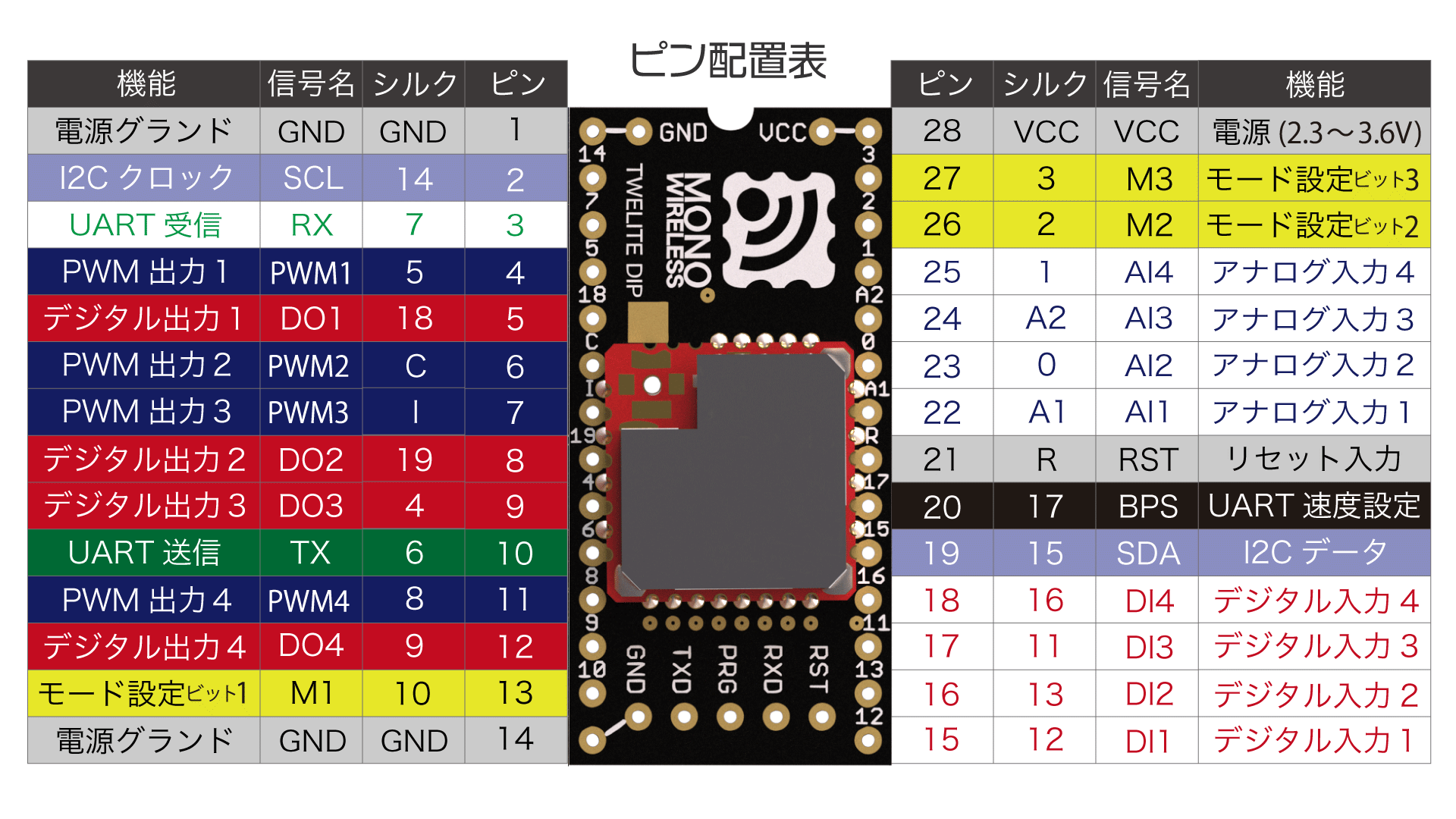
1 - Pin Assignment of Remote Control App
Functions of pins used by the Remote Control App
Unused pins should be left open.
TWELITE / TWELITE DIP
The functions of pins used by the Remote Control App are represented using the names from the diagram of Extremely Simple! Standard App Pins.
Sends input states to the parent device every 10 seconds, disables reception, and always enters power saving mode
✅
127
O: Not connected (OPEN), G: Connected to GND
Initial mode is Child: Continuous mode.
The initial Logical Device ID (LID) used to identify the device differs depending on the mode.
Only in parent or repeater modes, you can switch the LID in Interactive Mode.
Please set parent to 121 and repeater to 122.
Parent Device
Continuous Mode
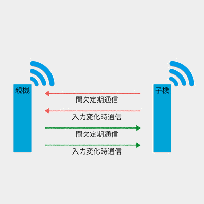
Parent: Continuous Mode
When a change in signal input is detected, or every second, data is sent to all child devices.
It also always waits for data sent from child devices, so it responds quickly but continuously consumes power.
Reception: Always waiting
Transmission: On input change / every 1 second
Child Device
Continuous Mode
Child: Continuous Mode
When a change in signal input is detected, or every second, data is sent to all parent devices.
It also always waits for data sent from parent devices, so it responds quickly but continuously consumes power.
Image of communication with parent device
Reception: Always waiting
Transmission: On input change / every 1 second
Disable periodic transmission
You can disable periodic transmission every 1 second by setting option bit 0x00000020 in Interactive Mode.
Child: Continuous 0.03s Mode
This mode shortens the periodic transmission interval of Child: Continuous Mode from 1 second to 0.03 seconds.
Although it always waits for data sent from the parent device, it occupies the bandwidth of communication from child to parent, causing slower response to parent input. It continuously consumes power.
Image of communication with parent device
Reception: Always waiting
Transmission: On input change / every 0.03 seconds
Since a single child device occupies most of the bandwidth, avoid using multiple child devices simultaneously if possible.
Intermittent Mode
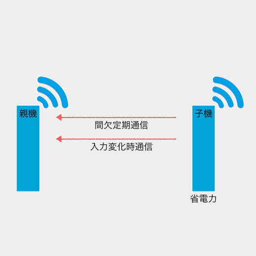
Child: Intermittent 1s Mode
When a change in signal input is detected, or every second, the power saving mode is disabled and data is sent to all parent devices.
Reception is disabled, so it cannot be controlled by the parent device. This mode has excellent power saving performance.
Image of communication with parent device
Reception: Disabled
Transmission: On input change / every 1 second
Child: Intermittent 10s Mode
When a change in signal input is detected, or every 10 seconds, the power saving mode is disabled and data is sent to all parent devices.
Reception is disabled, so it cannot be controlled by the parent device. This mode has excellent power saving performance.
Image of communication with parent device
Reception: Disabled
Transmission: On input change / every 10 seconds
Repeater Device
Continuous Mode
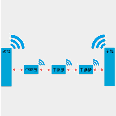
Repeater: Continuous Mode
The repeater transmits received packets.
You can install up to three repeaters between parent and child devices, but increasing repeaters increases the number of packets, which can cause interference.
Image of relay
Reception: Always waiting
Transmission: On reception
3 - Remote Control App Alternative Baud Rate Setting
Changing the baud rate used for UART communication
The Remote Control App (App_IO) uses 115200 bps as the default baud rate for UART communication, but this can be changed.
Enabling Alternative Baud Rate Setting
You can enable the alternative baud rate setting by connecting the BPS pin to GND.
The baud rate setting in Interactive Mode indicates the alternative baud rate. If the BPS pin is not connected to GND, the Interactive Mode setting value will not be applied.
Interactive Mode uses UART communication. When switching the baud rate of TWELITE, you must adjust the PC side baud rate before using Interactive Mode (TWELITE STAGE App Settings).
4 - Remote Control App UART Function
Data format used for UART function.
Explanation of data format used in the UART function of Remote Control App (App_IO).
Digital Input and Output
0x81: Status Notification from the Remote Device
Outputs the state of the received input signal.
Data Format
#
Data
Description
Remarks
char
Header
: only
0
uint8
Source Logical Device ID
1
uint8
Command Number
0x81 only
2
uint8
Packet Identifier
0x0F only
3
uint8
Protocol Version
0x01 only
4
uint8
LQI
0-255
5
uint32
Source Serial ID
0x8???????
9
uint8
Destination Logical Device ID
10
uint16
Timestamp
64 counts per second, MSB is internal flag
12
uint8
Relay Count
13
uint16
Digital Signal
Corresponds to Ix from LSB, 0 is High
15
uint16
Digital Signal Mask
Corresponds to Ix from LSB, 1 means valid
17
uint16
Digital Signal Flag
Corresponds to Ix from LSB, 1 means interrupt
19
uint8
Unused
For internal management
uint8
Checksum
LRC8
char
Footer
CR (0x0D/'\r')
char
Footer
LF (0x0A/'\n')
Example Output Data
:01810F01DB8630000200645F000040004F00400049
Interpretation of the Above Data
#
Data
Description
Value
:
char
Header
:
01
0
uint8
Source Logical Device ID
0x78
81
1
uint8
Command Number
0x81
0F
2
uint8
Packet Identifier
0x15
01
3
uint8
Protocol Version
0x01
DB
4
uint8
LQI
219/255
86300002
5
uint32
Source Serial ID
0x6300002
00
9
uint8
Destination Logical Device ID
0x00
645F
10
uint16
Timestamp
Approx. 401 seconds
00
12
uint8
Relay Count
0
0040
13
uint16
Digital Signal
I7 is Low
004F
15
uint16
Digital Signal Mask
I7,I1-I4 are valid
0040
17
uint16
Digital Signal Flag
I7 changed due to interrupt
00
19
uint8
Unused
49
uint8
Checksum
0x49
char
Footer
\r
char
Footer
\n
0x80: Remote Device Output Change
Controls the output signals of the remote device.
Data Format
#
Data
Description
Remarks
char
Header
: only
0
uint8
Destination Logical Device ID
Parent 0x00, Child 0x01-0x64, All Children 0x78
1
uint8
Command Number
0x80 only
2
uint8
Format Version
0x01 only
3
uint16
Digital Signal
Corresponds to Ox from LSB, 0 is High
5
uint16
Digital Signal Mask
Corresponds to Ox from LSB, 1 is valid
7
uint16
Unused
0
9
uint16
Unused
0
11
uint16
Unused
0
13
uint16
Unused
0
uint8
Checksum
LRC8
char
Footer
CR (0x0D/'\r')
char
Footer
LF (0x0A/'\n')
Parent and repeater apps (v1.2 and earlier) do not support this format.
There is a reported bug with TWELITE GOLD App_IO v1.3.2 where transmission commands may not work in some cases.
The cause is under investigation. For TWELITE STICK, please use App_Wings v1.3.2 (TWELITE Apps unified version is also available).
Usually, enter Interactive Mode with screen, then after pressing Ctrl+A, execute :exec !! lrx -b -X /path/to/conf.bin
If the download succeeds, it generates a 128-byte file (may be smaller depending on the xmodem implementation).
3. Creating Custom Binary
Concatenate the downloaded file to the end of the firmware binary file to create a custom binary.
Use command line tools or general file concatenation tools for concatenation.
Example
An example when the downloaded xmodem file is conf.bin, the original binary file is App_IO_BLUE_L1305_V1-3-X.bin, and the custom binary to be created is App_IO_custom_V1-3-X.bin.
【Windows】
copy App_IO_BLUE_L1305_V1-3-X.bin App_IO_custom_V1-3-X.bin
type conf.bin >> App_IO_custom_V1-3-X.bin
Create a group by generating an application ID based on the parent’s serial ID and feeding it to the child devices. Connect an LED to the LED pin to check if the configuration is successful.
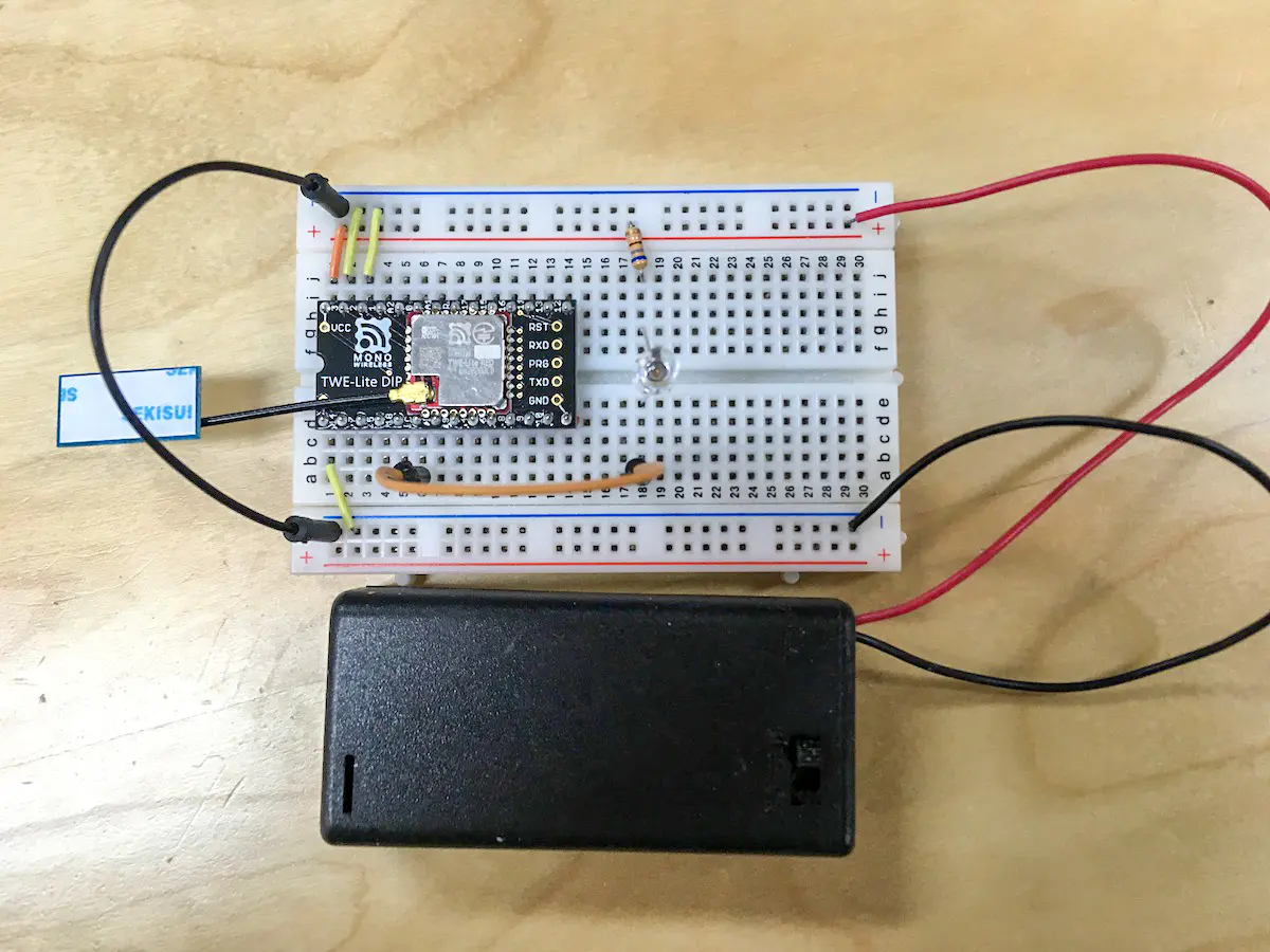
Connection
Connect an LED and a current limiting resistor (680Ω) to the LED pins of the parent and child devices (with correct polarity).
Leave M1 open and connect M2 and M3 to GND.
Power on the parent device and check that the LED blinks.
Within 5 seconds, power on the child device near the parent and confirm that the LED turns off (if it stays lit, the configuration failed).
7 - Interactive Mode (Remote Control App)
Configuration changes via Interactive Mode
You can perform detailed settings of the app via Interactive Mode.
This section explains features specific to the Remote Control App (App_IO). For common features, please refer to the TWELITE APPS Manual Top Page.
Interactive Mode cannot be used while TWELITE is sleeping.
Please ensure that the M3 pin is not connected to GND.
Display Example
The screen below will be displayed.
--- CONFIG/APP_IO V1-03-2/SID=0x86300001/LID=0x00 ---
 a: set Application ID (0x67720107)
 i: set Device ID (--)
 c: set Channels (16)
 x: set Tx Power (3)
 t: set mode4 sleep dur (1000ms)
 y: set mode7 sleep dur (0s)
 f: set mode3 fps (16)
 d: set hold mask (000000000000)
 D: set hold dur (1000ms)
 o: set Option Bits (0x00000000)
 b: set UART baud (38400)
 p: set UART parity (N)
 C: set crypt mode (0)
 K: set crypt key []
---
 S: save Configuration
 R: reset to Defaults
Set this when it is necessary to distinguish multiple child devices.
If distinction is not necessary or not possible, set to 120. If distinction is necessary, child devices should be any value from 1 to 100, and parent device should be 0 or 121.
Overwrite the intermittent interval of the child device intermittent 10-second mode from 10 seconds to another value. Unit is seconds.
If 0 is set, periodic wake-up by timer is disabled. In this case, the device wakes up on the falling edge of Ix, but not on the rising edge.
f: Child Device Continuous 0.03-Second Mode Cycle
Overwrite the number of transmission requests per second from 32 times to 4/8/16 times. Retry count is not included.
d: Hold/Long Press Mode Targets
By default, select ports targeted by hold mode, and when Option Bit 0x00000100 is enabled, select ports targeted by remote control long press mode.
Specify the bitmask of Ix or Ox ports to target. The value consists of up to 12 characters of 0 or 1. From LSB, the order is I1I2 … I12.
For example, specifying 000000001010 applies hold mode to I2 and I4. If any pin is targeted, ports not targeted output a 50ms pulse.
Hold Mode
In hold mode, targeted ports behave as follows:
Input (Transmission) side: Ix
After all inputs return from Lo to Hi, continuous transmission occurs for the configured duration (to release hold).
Output (Reception) side: Ox
For received inputs that are Lo, output holds Lo for the configured duration.
If during hold of any output, another Lo signal is received, the hold duration is extended.
Remote Control Long Press Mode
In remote control long press mode, targeted ports behave as follows:
Input (Transmission) side: Ix
Continuous transmission while any input is Lo.
After all inputs return from Lo to Hi, continuous transmission occurs for the configured duration.
Output (Reception) side: Ox
After packets with any input Lo are interrupted, outputs return Hi after the configured duration.
D: Hold/Long Press Mode Duration
By default, specify hold mode duration; when Option Bit 0x00000100 is enabled, specify hold duration or transmission interval for remote control long press mode.
Specify a value between 20 and 64000 ms.
Hold Mode
For hold mode, the configured duration applies as follows:
Input (Transmission) side: Ix
In continuous mode, the duration of continuous transmission after all inputs return from Lo to Hi.
In intermittent mode, the transmission interval while any input is Lo.
Output (Reception) side: Ox
The duration to maintain output.
Remote Control Long Press Mode
For remote control long press mode, the configured duration applies as follows:
Input (Transmission) side: Ix
The duration of continuous transmission after all inputs return from Lo to Hi.
Output (Reception) side: Ox
The time from interruption of packets with any input Lo until all outputs return to Hi.
o: Option Bits
Specify a 32bit number. Enable settings associated with each bit.
Overwrite the alternative baud rate selected when starting with the BPS pin connected to GND from 38400 bps.
Values can be selected from 9600/19200/38400/57600/115200/230400. Other values may cause errors.
If the BPS pin is left open at startup, this setting will not apply and will be fixed at 115200 bps.
p: UART Parity
Set to N (None), O (Odd), or E (Even). Stop bit is fixed to 1, hardware flow control is not supported.
C: Encryption
Specify whether encryption is enabled.
Set 1 to enable AES128bit encryption.
K: Encryption Key
Input the key used for encryption. Specify a 16-character text (binary sequences cannot be specified).
Details of Option Bits
Explanation of settings associated with each bit of the option bits value.
0x00000001: Low Latency Mode
Monitor input status and perform wireless transmission in low latency mode.
Shortens button monitoring time and minimizes transmission delay. In continuous mode, interrupts are used for input judgment but are more susceptible to chattering. In intermittent mode, reduces time to confirm input status.
Only valid for child devices.
0x00000002: Low Latency Mode (Sleep Interrupt)
When waking from sleep due to an interrupt from Ix going from Hi to Lo in intermittent mode, quickly send port information of the interrupt source.
Especially used in child device intermittent 10-second mode when periodic wake-up is disabled, combined with hold mode to detect button presses.