Pin Assignment of Remote Control App
TWELITE / TWELITE DIP
The functions of pins used by the Remote Control App are represented using the names from the diagram of Extremely Simple! Standard App Pins.
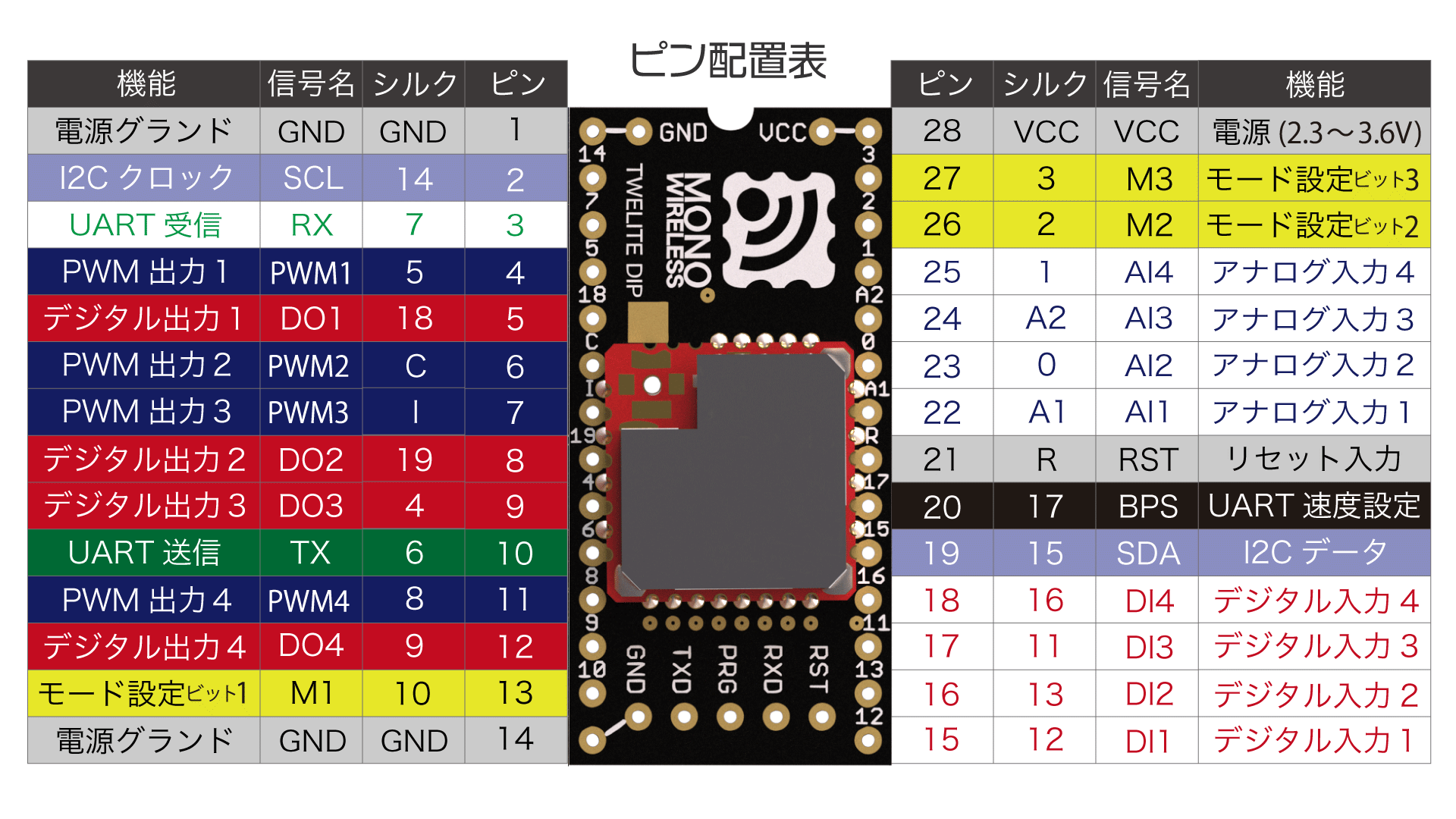
Super Simple! Standard App Pin Assignment Table
| DIP # | IO | Standard | Remote Control | Function |
|---|---|---|---|---|
| 1 | GND | GND | GND | Power Input |
| 2 | DIO14 | SCL | I9/O9 | Digital Input/Output |
| 3 | DIO7 | RX | RX | Serial Input/Output |
| 4 | DIO5 | PWM | I11/O11 | Digital Input/Output |
| 5 | DIO18 | DO1 | I5/O1 | Digital Input/Output |
| 6 | DO0 | PWM | LED | Status LED Output |
| 7 | DO1 | M3 | ||
| 8 | DIO19 | DO2 | I6/O2 | Digital Input/Output |
| 9 | DIO4 | DO3 | I7/O3 | Digital Input/Output |
| 10 | DIO6 | TX | TX | Serial Input/Output |
| 11 | DIO8 | PWM | I12/O12 | Digital Input/Output |
| 12 | DIO9 | DO4 | I8/O4 | Digital Input/Output |
| 13 | DIO10 | M1 | M1 | Mode Setting Input |
| 14 | GND | GND | GND | Power Input |
| 28 | VCC | VCC | VCC | Power Input |
| 27 | DIO3 | M3 | M3 | Mode Setting Input |
| 26 | DIO2 | M2 | M2 | Mode Setting Input |
| 25 | DIO1 | AI4 | C2 | Channel Setting Input |
| 24 | ADC2 | AI3 | ||
| 23 | DIO0 | AI2 | C1 | Channel Setting Input |
| 22 | ADC1 | AI1 | ||
| 21 | RESETN | RST | RST | Reset Input |
| 22 | DIO17 | BPS | BPS | Alternative Baud Rate Setting Input |
| 19 | DIO15 | SDA | I10/O10 | Digital Input/Output |
| 18 | DIO16 | DI4 | I4/O8 | Digital Input/Output |
| 17 | DIO11 | DI3 | I3/O7 | Digital Input/Output |
| 16 | DIO13 | DI2 | I2/O6 | Digital Input/Output |
| 15 | DIO12 | DI1 | I1/O5 | Digital Input/Output |
Power Input
Connect a 3.3V (2.0-3.6V) power supply to VCC/GND.
Digital Input/Output
Child: 12 inputs 0 outputs / Parent: 12 outputs 0 inputs
Default input/output assignments.
| Name | Child | Parent | Standard | DIP # |
|---|---|---|---|---|
I1/O5 | I1 | O5 | DI1 | 15 |
I2/O6 | I2 | O6 | DI2 | 16 |
I3/O7 | I3 | O7 | DI3 | 17 |
I4/O8 | I4 | O8 | DI4 | 18 |
I5/O1 | I5 | O1 | DO1 | 5 |
I6/O2 | I6 | O2 | DO2 | 8 |
I7/O3 | I7 | O3 | DO3 | 9 |
I8/O4 | I8 | O4 | DO4 | 12 |
I9/O9 | I9 | O9 | SCL | 2 |
I10/O10 | I10 | O10 | SDA | 19 |
I11/O11 | I11 | O11 | PWM1 | 4 |
I12/O12 | I12 | O12 | PWM4 | 11 |
Child: 8 inputs 4 outputs / Parent: 8 outputs 4 inputs
Input/output assignments when the option bit: 0x00001000 setting is enabled.
| Name | Child | Parent | Standard | DIP # |
|---|---|---|---|---|
I1/O5 | I1 | I1 | DI1 | 15 |
I2/O6 | I2 | I2 | DI2 | 16 |
I3/O7 | I3 | I3 | DI3 | 17 |
I4/O8 | I4 | I4 | DI4 | 18 |
I5/O1 | O1 | O1 | DO1 | 5 |
I6/O2 | O2 | O2 | DO2 | 8 |
I7/O3 | O3 | O3 | DO3 | 9 |
I8/O4 | O4 | O4 | DO4 | 12 |
I9/O9 | I5 | O5 | SCL | 2 |
I10/O10 | I6 | O6 | SDA | 19 |
I11/O11 | I7 | O7 | PWM1 | 4 |
I12/O12 | I8 | O8 | PWM4 | 11 |
Child: 6 inputs 6 outputs / Parent: 6 outputs 6 inputs
Input/output assignments when the option bit: 0x00002000 setting is enabled.
| Name | Child | Parent | Standard | DIP # |
|---|---|---|---|---|
I1/O5 | I1 | I1 | DI1 | 15 |
I2/O6 | I2 | I2 | DI2 | 16 |
I3/O7 | I3 | I3 | DI3 | 17 |
I4/O8 | I4 | I4 | DI4 | 18 |
I5/O1 | O1 | O1 | DO1 | 5 |
I6/O2 | O2 | O2 | DO2 | 8 |
I7/O3 | O3 | O3 | DO3 | 9 |
I8/O4 | O4 | O4 | DO4 | 12 |
I9/O9 | O5 | I5 | SCL | 2 |
I10/O10 | O6 | I6 | SDA | 19 |
I11/O11 | I5 | O5 | PWM1 | 4 |
I12/O12 | I6 | O6 | PWM4 | 11 |
Child: 0 inputs 12 outputs / Parent: 0 outputs 12 inputs
Input/output assignments when the option bit: 0x00003000 setting is enabled.
| Name | Child | Parent | Standard | DIP # |
|---|---|---|---|---|
I1/O5 | O5 | I1 | DI1 | 15 |
I2/O6 | O6 | I2 | DI2 | 16 |
I3/O7 | O7 | I3 | DI3 | 17 |
I4/O8 | O8 | I4 | DI4 | 18 |
I5/O1 | O1 | I5 | DO1 | 5 |
I6/O2 | O2 | I6 | DO2 | 8 |
I7/O3 | O3 | I7 | DO3 | 9 |
I8/O4 | O4 | I8 | DO4 | 12 |
I9/O9 | O9 | I9 | SCL | 2 |
I10/O10 | O10 | I10 | SDA | 19 |
I11/O11 | O11 | I11 | PWM1 | 4 |
I12/O12 | O12 | I12 | PWM4 | 11 |
Serial Input/Output
TX/RX are used for transmission and reception of the remote control (UART).
Status LED Output
Used when outputting status during automatic application ID setting.
Make the LED light up when the output is Low (sink type).
Setting Input
Mode Setting Input
By leaving the Mx pins unconnected or connecting them to GND, you can switch between operating modes such as parent, child, and repeater.
Alternative Baud Rate Setting Input
By leaving the BPS pin unconnected or connecting it to GND, you can change the UART baud rate (communication speed) to a value other than 115200bps.
Channel Setting Input
Temporarily overrides the frequency channel.
C2 | C1 | Frequency Channel |
|---|---|---|
| Unconnected | Unconnected | Default (initial value is 16) |
| Unconnected | GND | 12 |
GND | Unconnected | 21 |
GND | GND | 25 |
Reset Input
By connecting a push button between RST and GND, you can implement a reset button. RST is internally pulled up.