Pin Assignments of Extremely Simple! Standard App
Pin Assignments
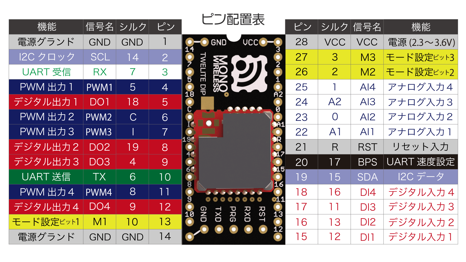
Pin Assignment Table
| Pin Name | Function |
|---|---|
VCC GND | Power Input |
DIx AIx | Digital/Analog Input |
DOx PWMx | Digital/Analog Output |
TX RX | UART |
SCL SDA | I2C |
Mx BPS | Configuration Input |
RST | Reset Input |
x represents any digit. For example, M1 M2 M3 are collectively represented as Mx.Power Input
Connect a 3.3V (2.3-3.6V) power supply to VCC/GND.
Digital and Analog Input/Output
DIx/DOx, AIx/PWMx pins transmit signals synchronously with matching pin numbers.
| Digital | Analog |
|---|---|
Input on DIx → Output on DOx | Input on AIx → Output on PWMx |
In the Extremely Simple! Standard App, the voltage range for analog input is set to 0-2V.
If a voltage above 2V is input, such as by connecting to VCC, it will be treated as unused.
Serial Communication
UART
TX/RX are used for UART transmission and reception. Specifically, they are used in the following cases:
- Wireless signal transmission
- UART signal transmission
- I2C signal transmission (on the parent device side)
- Wired communication with external devices
- Firmware management
- Firmware setting changes (Interactive Mode)
- Firmware rewriting
I2C
SCL/SDA pins are used to connect I2C target devices.
Configuration Input
By leaving the Mx pins unconnected or connecting them to GND, you can switch operation modes such as parent, child, and repeater (Operation Modes).
By leaving the BPS pin unconnected or connecting it to GND, you can change the UART baud rate from 115200bps to other values (Alternative Baudrate).
Reset Input
By connecting a push button between the reset input pin RST and GND, you can implement a reset button. RST is internally pulled up.