To install the Serial Communication App (App_Uart), install the TWELITE STAGE SDK and rewrite using the TWELITE STAGE App.
1 - Pin Assignments of Serial Communication App
Functions of pins used by the Serial Communication App
The following information applies to App_Uart v1.2 and later.
Unused pins should be left open.
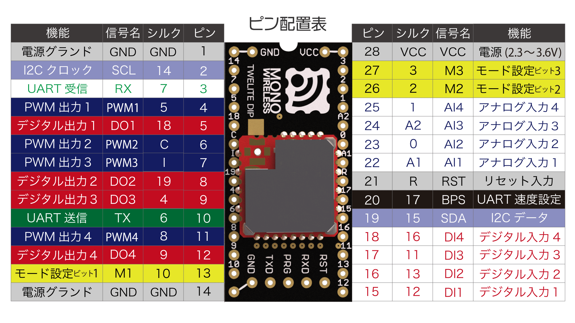
TWELITE / TWELITE DIP
The functions of pins used by the Serial Communication App are represented using the pin names from the Super Simple! Standard App Pins shown in the figure below.
Connect a 3.3V (2.0-3.6V) power supply to VCC/GND.
Serial Input and Output
TX/RX are used for transmitting and receiving serial communication (UART).
Since the level is 3.3V, when connecting to microcontrollers operating at 5V levels such as Arduino, please perform level conversion.
Serial Sub Input and Output
TX_SUB (SCL) / RX_SUB (SDA) can be used as sub-ports for serial input and output.
Serial Input Permission
When RTS (PWM1) is at Low level, it indicates that serial input to RX is being accepted.
By suppressing input to RX when at High level, it is expected to prevent data loss.
Parent/Child Selection
Connecting M1 to GND sets the device as a parent, while leaving it open or connecting to VCC sets it as a child.
Setting via Interactive Mode
You can omit this connection and configure it via the interactive mode.
i set Device ID: 0
Adding Relay Function to Child
When M2 is connected to GND in child mode, relay functionality can be added.
Setting via Interactive Mode
You can omit this connection and configure it via the interactive mode.
r set Role: 1 or 0x12
Sleep
Connecting M3 to GND puts the device into sleep mode.
Overwriting Operation Mode
By connecting EX1 to GND at startup, the operation mode can be overwritten to format mode (binary).
Enabling Alternative Baud Rate Setting
Connecting BPS to GND enables the alternative baud rate setting specified in interactive mode.
Reset Input
By connecting a push button between RST and GND, a reset button can be implemented. RST has an internal pull-up resistor.
Enter interactive mode
By connection SET to GND on startup, the interactive mode will be ready.
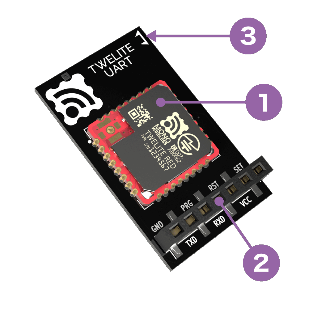
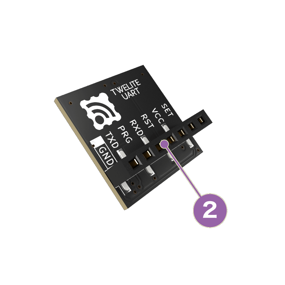
TWELITE UART
The functions of pins used by the Serial Communication App are represented using the pin names of the 7P interface printed on the board (② in the figure below).
Regardless of mode, please keep transmitted data within 80 bytes
Due to packet size constraints, please keep the data sent at one time within 80 bytes in binary.
The maximum length of packets in IEEE 802.15.4 adopted by TWELITE is 128 bytes, and considering overhead, the payload area available for the serial communication app is limited to 80 bytes.
If you need to send a large amount of data, please consider other products using Wi-Fi, etc. TWELITE is suitable for efficiently sending small amounts of data.
A: Format Mode (ASCII)
When data is input to the transmitting terminal according to a specific format, the receiving terminal outputs data according to the same specific format.
Data represented in hexadecimal is expressed as ASCII strings.
Input on Transmitting Side
Output on Receiving Side
Simple/Extended format data
→
Simple/Extended format data
In TWELITE UART, this mode is enabled when started with the SET pin connected to GND.
There are two formats to represent data.
Simple format: Uses only logical device ID. Super simple! Compatible with the standard app’s UART transmission function.
Extended format: Uses transmission options such as serial ID and retransmission count in addition to logical device ID.
For example, 5-byte binary data 0x48 0x45 0x4C 0x4C 0x4F can be sent using the simple format as follows.
[Transmitting Side]
:000148454C4C4F8B  <- Input
:DBA1800103  <- Output
[Receiving Side]
:780148454C4C4F13 <- Output
In format mode, settings such as application ID can be dynamically applied not only by Interactive Mode but also by commands via UART (ASCII format).
When data is input to the transmitting terminal according to a specific format, the receiving terminal outputs data according to the same specific format.
Data represented in hexadecimal is expressed in binary format as is.
Input on Transmitting Side
Output on Receiving Side
Simple/Extended format data
→
Simple/Extended format data
In TWELITE / TWELITE DIP, this mode is enabled when started with the EX1 pin connected to GND.
Like Format Mode (ASCII), there are two formats to represent data.
For example, 5-byte binary data 0x48 0x45 0x4C 0x4C 0x4F can be sent using the simple format as follows.
When arbitrary data is input to the transmitting terminal, the receiving terminal outputs the received content with auxiliary information added in a specific format.
Input on Transmitting Side
Output on Receiving Side
Any data
→
Any data + auxiliary information
By default, data input to the transmitting side is separated by CRLF, and data before CRLF is sent.
For example, when Hello<Enter> is input on the transmitting terminal, the receiving terminal outputs Hello in a format including auxiliary information. The transmitting terminal also outputs a format that conveys a transmission completion message.
The auxiliary information output by the receiving side includes the sender’s address, received signal strength, checksum, etc. The format of auxiliary information can be customized.
2.1 - Serial Communication App Format Mode (ASCII)
Mode that adds headers to both transmitted and received outputs (ASCII format)
Format mode adds headers to both transmitted and received outputs. In ASCII format, data is represented as hexadecimal strings.
Overview
When data formatted in a specific manner is input on the transmitting side, the receiving side outputs data formatted in the same manner.
Data is represented as hexadecimal ASCII strings.
Transmitting Side Input
Receiving Side Output
Simple/Extended format data
→
Simple/Extended format data
In TWELITE UART, format mode (ASCII) is enabled by starting up with the SET pin connected to GND.
In TWELITE / TWELITE DIP, format mode (binary) is enabled by starting up with the EX1 pin connected to GND.
There are two types of formats that can be handled.
Simple format: uses only the Logical Device ID. Extremely Simple! Compatible with the UART transmission function of the standard app.
Extended format: uses Logical Device ID plus transmission options such as Serial ID and retry count.
For example, 5-byte binary data 0x48 0x45 0x4C 0x4C 0x4F can be sent using the simple format as follows.
[Sending side]
:000148454C4C4F8B  <- Input
:DBA1800103  <- Output
[Receiving side]
:780148454C4C4F13 <- Output
Basic Format
When sending data sequences expressed in basic or extended formats, they are converted to ASCII strings (0-9, A-F).
The format is extremely simple! It starts with : and ends with CRLF, just like the output of the standard app (App_Twelite) or the parent device output of the parent/repeater app (App_Wings).
Header
Payload
Checksum
Footer
:
Repeated 00-FF
LRC8 of payload
CRLF
All ASCII characters
Starts with : (0x3A)
Checksum is the two’s complement of the sum of the payload
Ends with CRLF (\r\n/0x0D 0x0A)
Big-endian
For example, binary data 0x00 0x11 0x22 0x33 0xAA 0xBB 0xCC is expressed as follows.
:00112233AABBCC69<CR><LF>
Distinguishing Parent and Child Devices
Format mode distinguishes between parent and child devices.
If 1 second passes after input, the transmission process times out. Also, the internal buffer may become full with pending processes, and new requests cannot be accepted. When setting application retry or delay, be careful not to set extreme values.
0x01: Enable MAC ACK
Enables MAC layer ACK (acknowledgment).
Not suitable for frequent data transmission, but can improve reliability.
Not available for repeaters. Also, cannot be used when the destination is all children (0x78).
0x02: Enable Application Retry
When using MAC ACK, specify 0x00-0x0F. Retries 0-16 times respectively until the transmission succeeds.
When not using MAC ACK, specify 0x81-0x8F. Always retries 1-16 times.
Response messages are output after all retries are completed.
0x03: Minimum Initial Transmission Delay
Specifies the minimum delay before the first transmission in milliseconds.
0x04: Maximum Initial Transmission Delay
Specifies the maximum delay before the first transmission in milliseconds.
0x05: Application Retry Interval
Specifies the retry interval in milliseconds when application retry is enabled.
0x06: Allow Parallel Requests
Allows parallel requests.
When allowed, the next request can be accepted without blocking until the current request completes.
For example, if three requests with a 0.5-second delay are input consecutively, normally they are processed sequentially at 0.5s, 1.0s, and 1.5s. When parallel requests are allowed, they are processed in no particular order after 0.5s. Note that it cannot be used when packet fragmentation is required.
The receiving device always adopts the newest data. When parallel requests are allowed, old data may arrive after new data and be ignored.
0x07: Disable Response Messages
Disables the response messages output when data is input on the transmitting side.
0x08: Sleep After Transmission
Immediately puts the device to sleep after transmission.
When RX detects a rising edge, it wakes up from sleep. Please input any 1 byte of data.
After waking up, UART initialization completes and input is accepted.
Receiving Side Output
#
Data
Description
Notes
char
Header
Only :
0
uint8
Source Logical Device ID
Parent 0x00, child 0x01-0x64, unset child 0x78
1
uint8
Command number
Only 0xA0
2
uint8
Response ID
Value specified by the sender
3
uint32
Source Extended Address
Serial ID with 0x8 added at the front
7
uint32
Destination Extended Address
0xFFFFFFFF if using Logical Device ID
11
uint8
LQI
Radio communication quality at reception
12
uint16
Length of following byte sequence
Number of bytes (M)
14
[uint8]
Arbitrary data
Byte sequence of length (M)
uint8
Checksum
LRC8
char
Footer
CR (0x0D/'\r')
char
Footer
LF (0x0A/'\n')
Transmitting Side Output (Response Message)
#
Data
Description
Notes
char
Header
Only :
0
uint8
Source Logical Device ID
Only 0xDB: indicates itself
1
uint8
Command number
Only 0xA1
2
uint8
Response ID
Value specified at input
3
uint8
Result
Success 1, failure 0
uint8
Checksum
LRC8
char
Footer
CR (0x0D/'\r')
char
Footer
LF (0x0A/'\n')
Example Usage
An example of sending byte sequence 0x11 0x22 0x33 0xAA 0xBB 0xCC from the parent to a child is shown.
Example specifying Logical Device ID
An example sending from the parent to the child with Logical Device ID 0x42.
Response ID is 0x01
No options
Parent’s extended address is 0x81000000 (Serial ID 0x1000000)
Set bits for channels to be used. For example, to use channel 11, specify 1<<11.
0x02: Retry Count and Output
Specifies the radio transmission output and the number of additional packet transmissions in transparent mode and header-attached transparent mode.
Only the lower 1 byte is used. The upper 4 bits represent the retry count (0-9), and the lower 4 bits represent the transmission output (0-3). For example, 8 retries / output 3 is 0x0083.
0x03: Logical Device ID
Specifies the logical device ID.
0x04: Role
Effective only for slave devices. Specify one of the following values. Normally, select a delivery method that does not use the network layer.
Delivery Methods Without Network Layer
0: Normal designation (parent or child device)
1-3: Relay slave devices (logical device IDs are 1-100 or 120). Numbers 1-3 indicate the maximum relay hop count. This method retransmits up to the maximum relay hops, which may cause duplicate packets depending on relay device placement and count.
Delivery Methods Using Network Layer
11: Parent device
12: Relay device
13: Child device
To enable silent mode, add 80 to the above values. For example, 93 means “network layer enabled and silent mode”.
0x05: Relay Layer
The relay layer number. Relay devices attempt to connect to relay devices or parent devices in upper (smaller value) relay layers. Effective only when Role is set to 12.
0x06: Communication Mode
0: Transparent mode
1: Format mode (ASCII)
2: Format mode (Binary)
3: Chat mode
4: Header-attached transparent mode
0x07: Baud Rate
Specifies the UART baud rate.
0x08: Parity
Specifies the sum of settings in the following combination:
Bit
0: 8Bit
8: 7Bit
Parity
0: None
1: Odd
2: Even
Stop
0: STOP 1
4: STOP 2
For example, 7-E-1 is specified as 8+2+0=10(0xA).
0x09: Encryption Function
Specifies whether encryption is enabled.
0: Disabled
1: AES128bit encryption enabled
0x0A: Encryption Key
Specifies a 16-byte encryption key.
Can store binary sequences that cannot be set in Interactive Mode. This may cause display issues in Interactive Mode.
0x0B: Header / Handle name
Specifies a header format on the mode E or handle name on the mode C.
0x0C: Delimiter Character
Specifies the delimiter character (0x00-0xFF).
2.2 - Serial Communication App Format Mode (Binary)
Mode that adds headers to both transmitted and received outputs (binary format)
Format mode adds headers to both transmitted and received outputs. In binary format, data is represented as raw binary.
Overview
When data formatted in a specific manner is input on the transmitting side, the receiving side outputs data formatted in the same manner.
Data represented in hexadecimal is output as raw binary.
Transmitting Side Input
Receiving Side Output
Simple/Extended Format Data
→
Simple/Extended Format Data
On TWELITE UART, format mode (ASCII) is enabled by connecting the SET pin to GND at startup.
On TWELITE / TWELITE DIP, format mode (binary) is enabled by connecting the EX1 pin to GND at startup.
There are two types of supported formats.
Simple format: uses Logical Device ID only; Extremely Simple! Compatible with UART transmission function of the standard app
Extended format: uses Logical Device ID plus options such as Serial ID and retry count
For example, 5 bytes of binary data 0x48 0x45 0x4C 0x4C 0x4F can be transmitted using the simple format as follows.
Hereafter, the 0x in binary data representation is omitted.
For example, 0x48 0x45 0x4C 0x4C 0x4F is represented as 48 45 4C 4C 4F.
If 1 second passes after input, the transmission process times out. Also, if the internal buffer becomes full with pending processes, new requests may not be accepted. When setting application retransmission or delay, avoid extreme values.
0x01: Enable MAC ACK
Enables MAC layer ACK (acknowledgment).
Not suitable for frequent data transmissions but can improve reliability.
Relay devices cannot use this. Also, it cannot be used when the destination is all children (0x78).
0x02: Enable Application Retransmission
When using MAC ACK, specify 0x00-0x0F. Retransmits 0-16 times until successful.
When not using MAC ACK, specify 0x81-0x8F. Always retransmits 1-16 times.
Response messages are output after all retransmissions are complete.
0x03: Minimum Initial Transmission Delay
Specifies the minimum delay before the first transmission in milliseconds.
0x04: Maximum Initial Transmission Delay
Specifies the maximum delay before the first transmission in milliseconds.
0x05: Application Retransmission Interval
Specifies the interval between application retransmissions in milliseconds.
0x06: Allow Parallel Requests
Allows parallel requests.
When allowed, the next request can be accepted without blocking until the previous request completes.
For example, if three requests each with 0.5 seconds delay are input consecutively, normally they are processed sequentially at 0.5s, 1.0s, and 1.5s. With parallel requests allowed, they are processed in any order after 0.5s. Note that this cannot be used when packet segmentation is required.
Receiving devices always adopt the newest data. When parallel requests are allowed, older data may arrive after newer data and be ignored.
0x07: Disable Response Messages
Disables response messages output when data is input on the transmitting side.
0x08: Sleep After Transmission
Immediately puts the device to sleep after transmission.
RX detects rising edge to wake from sleep. Input any 1 byte of data.
After waking, UART initialization completes and input is accepted.
Receiving Side Output
#
Data
Description
Notes
uint8
Header
Only 0xA5
uint8
Header
Only 0x5A
uint16
Data Length
\(M\)+14
0
uint8
Source Logical Device ID
Parent 0x00, Child 0x01-0x64, Unset Child 0x78
1
uint8
Command Number
Only 0xA0
2
uint8
Response ID
Value specified by sender
3
uint32
Source Extended Address
Serial ID with 0x8 added at the front
7
uint32
Destination Extended Address
0xFFFFFFFF when using Logical Device ID
11
uint8
LQI
Radio signal quality at reception
12
uint16
Length of Following Bytes
Byte count \(M\)
14
[uint8]
Arbitrary Data
Byte sequence of length \(M\)
uint8
Checksum
XOR
uint8
Footer
EOT (0x04)
Transmitting Side Output (Response Message)
#
Data
Description
Notes
uint8
Header
Only 0xA5
uint8
Header
Only 0x5A
uint16
Data Length
4
0
uint8
Source Logical Device ID
Only 0xDB: indicates itself
1
uint8
Command Number
Only 0xA1
2
uint8
Response ID
Value specified on input
3
uint8
Result
Success 1, Failure 0
uint8
Checksum
XOR
uint8
Footer
EOT (0x04)
Examples
Example of sending byte sequence 11 22 33 AA BB CC from parent to child.
Example specifying Logical Device ID
Example of sending from parent to child with Logical Device ID 0x01.
Response ID is 0x01
No options
[Transmitting Side: Parent]
A5 5A 80 0A 01 A0 01 FF 11 22 33 AA BB CC 82 04  <- Input
A5 5A 80 04 DB A1 01 01 7A 04  <- Output
The last byte 0xC1 is checksum: XOR from 0x42 to 0xCC.
Set bits for channels to use. For example, to use channel 11, set 1<<11.
0x02: Retry Count and Output
Specifies the radio transmission output and the number of additional packets to send in transparent mode and header-attached transparent mode.
Only the lower 1 byte is used. The upper 4 bits indicate retry count (0-9), and the lower 4 bits indicate transmission output (0-3). For example, 8 retries/output 3 is 0x0083.
0x03: Logical Device ID
Specifies the logical device ID.
0x04: Role
Valid only for child devices. Specify the following values. Usually, select a delivery method without using the network layer.
Delivery Methods Without Using Network Layer
0: Normal designation (parent or child)
1-3: Relay child devices (logical device IDs 1-100 or 120). Numbers 1-3 indicate maximum relay hops. This method repeats retries up to the maximum relay hops, which may cause duplicate packets depending on relay device placement and number.
Delivery Methods Using Network Layer
11: Parent device
12: Relay device
13: Child device
To enable silent mode, add 80 to the above values. For example, 93 means “using network layer and silent mode”.
0x05: Relay Layer
The relay layer number. Relay devices attempt to connect to relay devices or parent devices with higher layers (lower values). Effective only when Role is set to 12.
0x06: Communication Mode
0: Transparent mode
1: Format mode (binary)
2: Format mode (binary)
3: Chat mode
4: Header-attached transparent mode
0x07: Baud Rate
Specifies UART baud rate.
0x08: Parity
Specifies the sum of settings in the following combination.
Bit
0: 8Bit
8: 7Bit
Parity
0: None
1: Odd
2: Even
Stop
0: STOP 1
4: STOP 2
For example, 7-E-1 is 8+2+0=10(0xA).
0x09: Encryption Function
Specifies whether encryption is enabled.
0: Disabled
1: AES128bit encryption enabled
0x0A: Encryption Key
Specifies a 16-byte encryption key.
Allows storing binary sequences that cannot be set in Interactive Mode. In this case, the display in Interactive Mode may be disrupted.
0x0B: Header / Handle name
Specifies a header format on the mode E or handle name on the mode C.
0x0C: Delimiter Character
Specifies the delimiter character string (0x00-0xFF).
2.3 - Serial Communication App Chat Mode
Mode that displays prompts and performs echo back
Chat mode realizes text chat through prompt display and echo back.
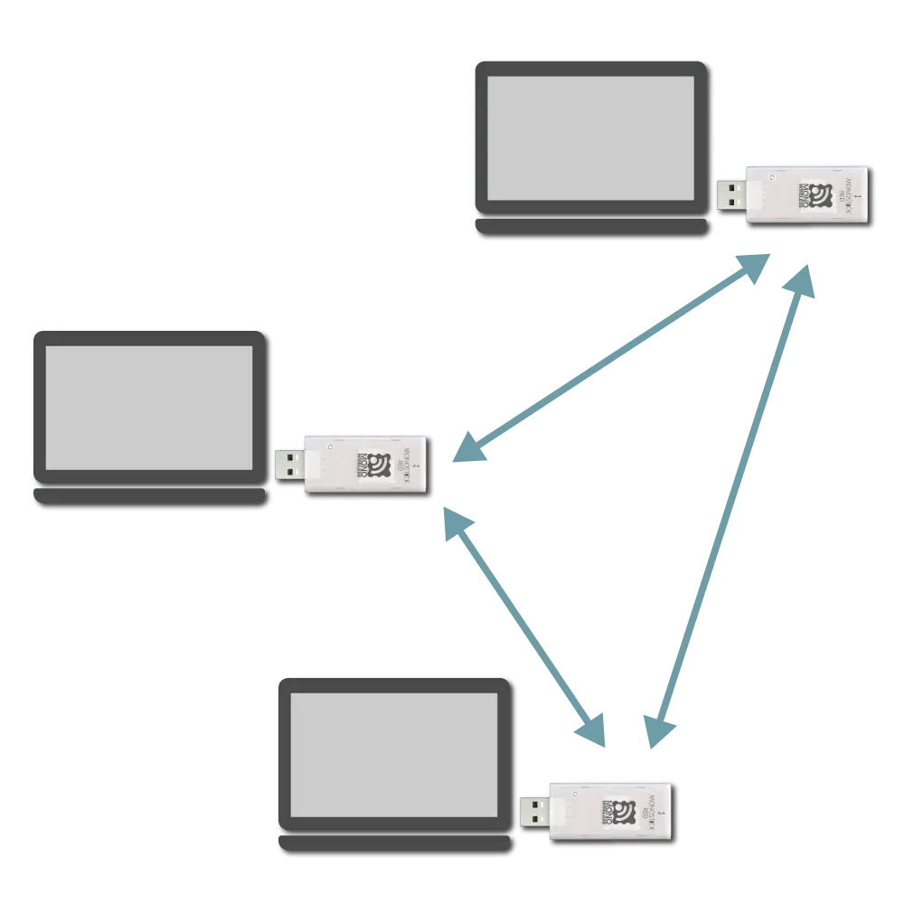
By connecting MONOSTICK to a PC etc., chat can be performed among multiple terminals.
Overview
Enables text chat.
Sending Side Input
Receiving Side Output
Any string
→
Any string + auxiliary information
Displays prompt and echoes back (outputs input characters). All terminals operate as child devices, performing broadcast communication.
For example, when sending the string Hello from one terminal to another, it behaves as follows.
Chat mode displays prompt and echoes back (outputs input characters entered by itself).
All terminals are treated as child devices and broadcast their transmitted content. Communication is possible with all terminals but destination cannot be specified. Binary data cannot be sent. Only strings are supported (0x00-0x1F, 0x7F cannot be sent).
Relay supports up to 3 hops. Relay is disabled by default.
Distinction between Parent and Child Devices
Chat mode does not distinguish between parent and child devices.
If the Application ID and frequency channel are the same, data entered in any terminal is sent to other terminals.
Network configuration image
Identification of Source
The auxiliary information in the received output can identify the sender.
If the Interactive Mode’s h: Header format is blank, the 7-digit serial ID with a leading 0x8 is used as the extended address. For example, the following output indicates the sender’s serial ID was 0x10A4778.
[810A4778:0] Hello
If h: Header format is set to an arbitrary string, it is used as the handle name. Handle name consumes data space in the wireless packet.
Sending Side Input Format
Enter message and newline after prompt.
Data
Content
Remarks
[char]
Message
0x00-0x1F, 0x7F not allowed
char
CR (0x0D/'\r')
Allowed alone
char
LF (0x0A/'\n')
Allowed alone
810A4778:0> Hello
Receiving Side Output Format
Outputs received message following auxiliary info.
Auxiliary information includes the module’s extended address or handle name and a sequence number.
Data
Content
Remarks
char
Auxiliary info header
[ only
[char]
Identification info
8-digit extended address or handle name
char
Auxiliary info delimiter
: only
[char]
Sequence number
Starting from 0
char
Auxiliary info footer
] only
char
Separator
Space only
[char]
Message
char
Footer
CR (0x0D/'\r')
char
Footer
LF (0x0A/'\n')
In case of errors etc., messages enclosed in parentheses like (err) or (canceled) are output.
[810A4778:0] Hello
Other Inputs
Terminals supporting escape sequences can use the following control commands.
Ctrl-L: Clear screen
Ctrl-C: Cancel input
BS/DEL: Move cursor back
2.4 - Serial Communication App Transparent Mode
Mode that purely wirelesss UART
Transparent mode realizes behavior similar to UART connected by wires without adding headers, echo back, or prompt display.
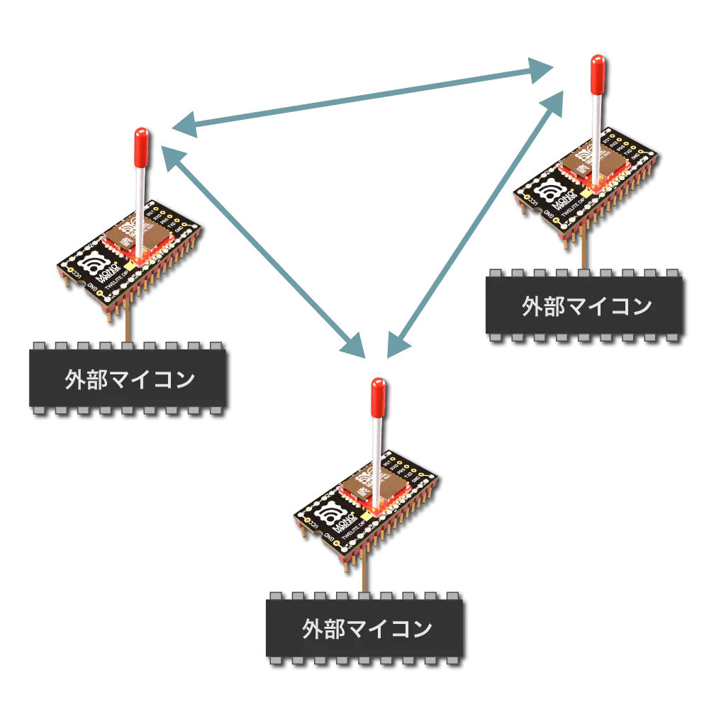
External microcontrollers can be easily connected, but to optimize communication using formats, format modes (ASCII / Binary) are suitable.
Overview
Purely wirelesss UART.
Sending side input
Receiving side output
Any data
→
Any data
Since no format is required, existing UART communication can be easily wirelessized.
However, data delimiters are ambiguous and it is impossible to identify the sender from the receiver output.
The initial state specifies CRLF as the transmission trigger character. Therefore, data input to the transmitter is separated by CRLF, and the data before CRLF is transmitted.
For example, entering Hello<Enter> on the transmitting terminal results in Hello being output on the receiving terminal.
[Sending side]
Hello <- Input
[Receiving side]
Hello <- Output
Continuous input strings are split and sent in chunks of 80 bytes. Data up to the trigger character should normally be 80 bytes or less.
All terminals are considered child devices, and the transmitted content is broadcast. Communication with all terminals is possible, but the destination cannot be specified. Both ASCII characters and binary data can be sent.
Relay supports up to 3 hops. By default, relay is disabled.
Distinction between Parent and Child Devices
Transparent mode does not distinguish between parent and child devices.
If application ID and frequency channel are the same, data entered into any terminal is sent to other terminals.
Network configuration image
Identification of Sender
Transparent mode cannot identify the sender.
To identify sender, sender information must be included in data input to the transmitter.
Transmission Trigger
Transmission trigger must be considered, as data is divided and transmitted wirelessly packet by packet.
Therefore, the following transmission triggers must be taken into account:
When a timeout after data input is reached
When the input data reaches the minimum data size
When the transmission trigger character is received
Transmission Trigger Priority
When timeout is reached, transmission is forced. Also, if a minimum data size is set, the transmission trigger character is invalid unless that size is met.
Transmission trigger settings can be specified from the interactive mode k: Transmission Trigger item.
Example Setting
When setting the transmission trigger character to LF, minimum data size to 8 bytes, and timeout to 30 ms, set as follows:
 m: set UART mode (D)
 k: set Tx Trigger (sep=0x0a, min_bytes=8 dly=30[ms])
 o: set option bits (0x00000100)
2.5 - Serial Communication App Header Transparent Mode
Mode that adds headers only to the received output
Header Transparent Mode adds auxiliary information only to the output on the receiving side.
Overview
Enabled by default.
When arbitrary data is input to the transmitting terminal, the receiving terminal outputs data with auxiliary information in a specific format.
Transmitting side input
Receiving side output
Any data
→
Any data + auxiliary info
By default, data input on the transmitting side is separated by CRLF and data before CRLF is sent.
For example, entering Hello<Enter> on the transmitting side results in output Hello with auxiliary info on the receiving side. The transmitting side also outputs a message indicating transmission completion.
The auxiliary information output by the receiving side includes the source address, received signal strength, checksum, etc. The format of the auxiliary information can be customized.
Distinction between Parent and Child Devices
Header Transparent Mode does not distinguish between parent and child devices.
The source logical device ID is 219 for its own response message.
The extended address is the 7-bit serial ID printed on the TWELITE device with a leading 0x8 added.
Customization by Header Format
The output format on the receiving side follows the header format.
Changing the header format customizes the content of the auxiliary information output and the checksum calculation range.
The default header format is ;U;%t;%i;0x%A;%q;%s;<*;%X;\n.
The header format can be changed via the interactive mode command h: set header format.
Simplest Format
The simplest header format is *\n. It outputs the received data with CRLF line endings.
h: set header format [*\n]
When sending HELLO in this case, it behaves as follows.
[Receiving side]
HELLO<CR><LF> or HELLO<LF>
[Transmitting side]
HELLO<CR><LF>
Special Characters in Header Format
You can customize the output by including the following special characters in the header format.
General
Description
*
Received data
&hl
Arbitrary ASCII character (e.g., &20 is space)
<
Start position for checksum calculation (default is start of string)
>
End position for checksum calculation (only from v1.4.6)
Characters following \ (backslash)
Description
\n
CRLF (0x0D0x0A)
\t
TAB
\*
*
\%
%
\<
<
\>
>
\&
&
Characters following %
Description
Length
Data format
%A
Source address (32bit)
8 chars
Hexadecimal
%a
Source address (32bit)
10 chars
Hexadecimal
%I
Source logical address (8bit)
2 chars
Hexadecimal
%i
Source logical address (8bit)
3 chars
Decimal
%T
Current system time (seconds)
4 chars
Hexadecimal
%t
Current system time (seconds)
5 chars
Decimal
%S
Source sequence number (hex)
2 chars
Hexadecimal
%s
Source sequence number (hex)
3 chars
Hexadecimal
%Q
Received signal strength
2 chars
Hexadecimal
%q
Received signal strength
3 chars
Decimal
%X
Checksum
2 chars
Hexadecimal
%x
Checksum
3 chars
Decimal
Checksum Calculation
The checksum is calculated by XOR (exclusive OR) from the start of the data or from the position indicated by < in the header format up to just before %X or %x.
Example in Default State
The default header format is ;U;%t;%i;0x%A;%q;%s;<*;%X;\n, where the checksum calculation range is *;.
That is, when sending HELLO, the binary data HELLO; is targeted, resulting in checksum 0x79.
[Verification code in Python]
from functools import reduce
defmain():
data ="HELLO;" checksum = reduce(lambda x, y: x ^ y, data.encode("ascii"))
print(f"{data} -> {hex(checksum)}")
if __name__ =="__main__":
main() # HELLO; -> 0x79
Other Examples
For example, consider the header format ;%I;*;%X.
Since < is not specified, the checksum calculation range is ;%I;*;.
That is, when sending HELLO, the binary data ;000;HELLO; is targeted, resulting in checksum 0x49.
[Verification code in Python]
from functools import reduce
defmain():
data =";000;HELLO;" checksum = reduce(lambda x, y: x ^ y, data.encode("ascii"))
print(f"{data} -> {hex(checksum)}")
if __name__ =="__main__":
main() # ;000;HELLO; -> 0x49
Transmission Trigger
There is no format on the transmitting side input, but data is split and transmitted packet by packet.
Therefore, the following transmission triggers must be considered.
When timeout after data input occurs
When input data reaches the minimum data size
When a transmission trigger character is received
Priority of Transmission Triggers
When timeout occurs, transmission is forced. Also, if a minimum data size is set, the transmission trigger character is invalid unless that size is reached.
Set this value if it is necessary to distinguish between multiple child devices.
If no distinction is needed or possible, set it to 120. If distinction is required, use any value between 1 and 100 for child devices, and use 121 for parent devices.
Valid for child devices only. Select one of the following. Normally, use a transmission mode that does not rely on the network layer (LayerTree).
Transmission Modes Not Using the Network Layer
0: Default (Parent or Child)
1–3: Repeater Child (set Logical Device ID to 1–100 or 120). The value indicates the maximum number of relay hops. Duplicated packets may occur depending on placement and number of repeaters.
Transmission Modes Using the Network Layer
Only supported in Header Transmission Mode.
11: Parent
12: Repeater
13: Child
l: LayerTree Relay Layer
Specifies the relay layer number. A repeater attempts to connect to parent or repeater devices with higher relay layers (smaller values). Valid only when Role is set to 12.
m: Communication Mode
A: Format Mode (ASCII)
B: Format Mode (Binary)
C: Chat Mode
D: Transparent Mode
E: Header Transmission Mode
t: TX Trigger Characters
In Transparent and Header Transmission modes, entering these characters triggers transmission of a packet.
If Minimum Data Size is specified, the characters will be ignored until that size is reached.
This setting is applied when Option Bit 0x00000100 (enabled by default) is set.
Initially, CRLF is used as the trigger.
u: Minimum Data Size
Specifies the minimum size of data to be handled continuously. TX Trigger Characters are ignored until this size is met.
In Interactive Mode, specify a number between 1–80 as byte count. Set to 0 to disable. The default is disabled.
T: Timeout
Time to wait from the last input before transmitting a packet.
In Interactive Mode, specify a value between 10–200 in milliseconds. Set to 0 to disable. The default is disabled.
This setting takes precedence over TX Trigger Characters and Minimum Data Size.
h: Header Format / Handle Name
Specifies the header format for Header Transmission Mode, or the handle name for Chat Mode.
Specify the handle name to display on the receiving device.
Up to 23 characters. This consumes part of the data transmission area (80 bytes).
C: Encryption
Specifies whether to enable encryption.
To enable AES128-bit encryption, set this to 1.
Devices with encryption enabled can receive plaintext messages, but cannot use Ack responses.
K: Encryption Key
Specify a 16-character encryption key when encryption is enabled.
Option Bits Details
This section describes each setting associated with the bits of the Option Bits value.
00000001: Disable Internal Pull-up of M3
Disables the internal pull-up resistor of the M3 pin used for sleep configuration on TWELITE DIP.
Do not boot in open state when the pull-up is disabled, as it may unintentionally enter sleep mode.
00000100: Enable TX Trigger
Enables the TX Trigger setting in Transparent or Header Transmission Mode.
This is enabled by default.
00000200: Prioritize New Input Stream
In Format Mode (ASCII/Binary), Transparent Mode, and Header Transmission Mode, if multiple input streams are received before the previous transmission is complete, the newer input is prioritized.
Useful when sending continuous control or measurement data to ensure the latest values are reflected.
00001000: Suppress Response Message
In Format Mode (ASCII/Binary) and Header Transmission Mode, suppresses the response message after transmission completes.
00004000: Relax Duplicate Checker
Relaxes the duplicate check conditions on the receiver side.
The duplicate checker prevents redundant packets that may arrive due to relays.
If the transmission interval is short (e.g., under 100 ms), even different packets might be mistakenly recognized as duplicates (even with different sequence numbers).
Enable this option when using short intervals or multiple transmitters concurrently.
Since Interactive Mode also uses UART, make sure to match the baud rate on the PC side when using Interactive Mode.
00020000: Simultaneous Output to Sub Port
Also outputs serial TX data to the secondary TX_SUB port.
The I/O buffer (4KB input, 4KB output) is split equally between the main and sub ports (2KB input, 2KB output each).
00040000: Switch Primary Port
Switches the serial I/O between the main TX/RX and the sub TX_SUB/RX_SUB ports.
About Repeater Function
When the communication range is insufficient or obstructed, using a repeater can be effective.
A repeater device retransmits packets it receives to other devices.
01000000: Disable LED
Disables the LED on TWELITE STICK and MONOSTICK.
02000000: Disable LED in Standby
Disables the LED on TWELITE STICK and MONOSTICK while in standby.
Configuring Repeater Function
Normally, enter Interactive Mode and change the Role to a value between 1 and 3. The default is 0, which does not enable the repeater function.
r: set Role (0x0)
The values 1 to 3 indicate the maximum number of relay hops. For example, setting it to 3 allows up to 3 hops.
This setting is only valid for child devices, not for parent devices.
Increasing the number of repeater hops or repeaters will also increase the number of packets transmitted. Communication within the same frequency channel may become unstable.
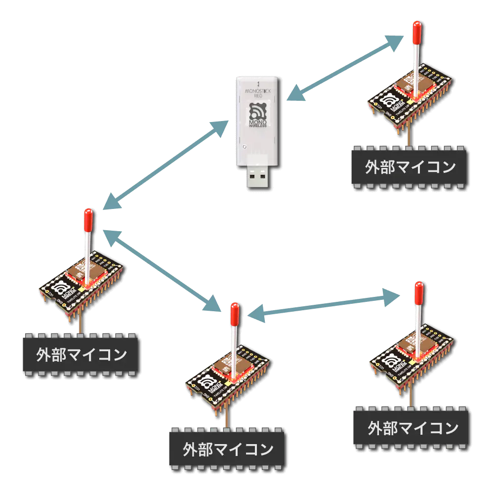
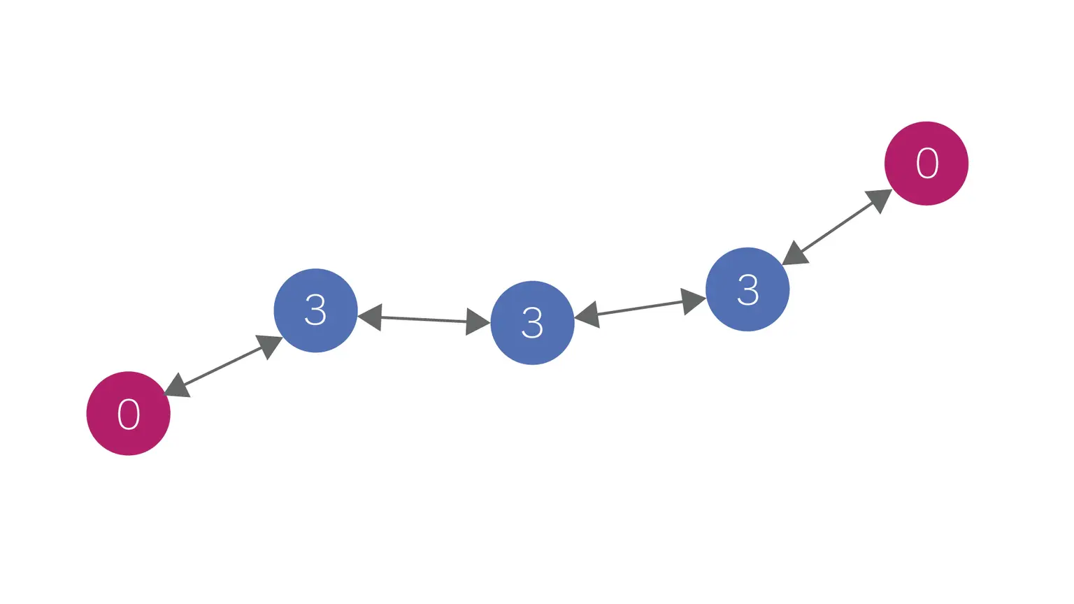
Example Configuration
The following network configuration shows an example where the Role of red devices is set to 0, and that of blue devices is set to 3.
Example of relaying via Role setting
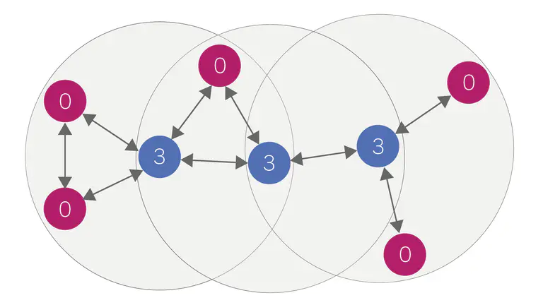
By adding more red devices, communication with up to three relay hops between them can be established.
Example of adding transmitters and receivers
4 - Notes on Communication in Serial Communication App
Precautions for stable communication
Precautions for achieving stable communication.
UART Data Input and Output
4KB buffers are allocated for UART input and output. When outputting two UART lines, 2KB is used for input and output buffers for each line.
In format mode and chat mode, it is rarely necessary to be aware of buffer sizes, but in header transparent mode and transparent mode when continuously inputting streams, or even in format mode when inputting many streams at once, it is necessary to be aware of the buffer size limits. On the output side, if a slow baud rate is set, the output of data received wirelessly may not keep up.
Data beyond the buffer limits is not protected at the boundary, causing data loss. Especially on the input side, consider referring to the flow control pins described below.
UART Flow Control
Input flow control is implemented to behave like the RTS pin. The pin used is PWM1 (DIO5), targeting the main UART port. When input is not accepted, the state is High; when input is accepted, the state is Low. Output flow control is not supported. Receiving devices should ensure sufficient baud rate and processing speed.
After power-on or reset, the pin is High. It becomes Low once UART is initialized.
When the UART input buffer exceeds 7/8 full, the pin goes High; it goes Low when below that threshold.
In transparent mode, the pin is High during packet transmission.
Countermeasures for Wireless Communication Errors
If data loss occurs on the receiving side, increase the number of wireless retransmissions.
Increasing the number of additional packets sent can improve the success rate of reception.
The number of retransmissions can be set in Interactive Mode (x: set RF Conf).
5 - Custom Default Feature of Serial Communication App
Creating firmware with changed default settings
Only available on single versions of the App for BLUE / RED series.
With the custom default feature, you can change the default parameters included in the firmware.
For example, if you create firmware that changes the baud rate from 115200bps to 9600bps, you can use it at 9600bps from the start.
Usually, enter Interactive Mode with screen, then press Ctrl+A and execute :exec !! lrx -b -X /path/to/conf.bin
If the download succeeds, a 128-byte file is generated (may be smaller depending on xmodem implementation).
3. Creating Custom Binary
Concatenate the downloaded file to the end of the firmware binary file to create a custom binary.
Use command line tools or general file concatenation tools for concatenation.
Example
Example assuming downloaded xmodem file is conf.bin, original binary file is App_Uart_BLUE_L1305_V1-4-X.bin, and custom binary to create is App_Uart_custom_V1-4-X.bin.
【Windows】
copy App_Uart_BLUE_L1305_V1-4-X.bin App_Uart_custom_V1-4-X.bin
type conf.bin >> App_Uart_custom_V1-4-X.bin