Interactive Mode (Serial Communication App)
This section describes features specific to the serial communication app (App_Uart). For common functions, refer to the TWELITE APPS Manual Top Page.
Interactive Mode cannot be used while TWELITE is in sleep mode.
Make sure that the M3 pin is not connected to GND.
Display Example
[CONFIG MENU/App_Uart:0/v1-05-1/SID=8300051A]
a: (0x67720103) Application ID [HEX:32bit]
i: (       120) Device ID [1-100,etc]
c: (18        ) Channel(s)
x: (      0x03) RF Power/Retransmissions [HEX:8bit]
b: (115200,8N1) UART Baud Alt. [XXXXX]
o: (0x00000100) Option bits [HEX:32bit]
r: (      0x00) Role [0-3,11-13]
l: (         1) LayerTree repeat layer [1-63]
m: (E         ) UART mode [ABCDE]
t: (    0x0D0A) Tx trigger character [XX,XXYY]
u: (         0) Minimum data size [0,1-80]
T: (         0) Timeout [0,10-200 msec]
h: (;U;%t;%i;0x%A;%q;%s;<*;%X;\n) Header format / Handle name
C: (         0) Encryption [0,1]
K: (*CRYPT_KEY_HERE*) Encryption key [16chrs]

 [ESC]:Exit [!]:Reset System [*]:Extr Menu [:]:AppSel
Commands
| Parameter | Default | Remarks | |
|---|---|---|---|
a | Application ID | 0x67720103 | 32bit |
i | Logical Device ID | 120 | Parent 121, Child 1-100, No ID Child 120 |
c | Frequency Channel | 18 | 11-26 |
x | TX Power & Retransmit Count | 0x03 | |
| Retransmit Count | 0 | 1-9 times, 0 disables | |
| TX Power | 3 | 0-3 | |
b | UART Alternate Setting | 115200,`8N1 | Enable with BPS pin |
o | Option Bits | 0x00000000 | Other detailed settings |
r | Role | 0 | Normal 0, Relay Child 1-3, Other |
l | LayerTree Relay Layer | 0x01 | |
m | Communication Mode | E | A/B/C/D/E |
t | TX Trigger Characters | 0x0D0A | ASCII code of trigger characters |
u | Minimum Data Size | 0 | Disabled 0, 1-80 |
T | Timeout | 0 | Disabled 0, 10-200ms |
h | Header Format / Handle Name | Details | |
| Header Format | When using Header Transmission Mode | ||
| Handle Name | When using Chat Mode | ||
C | Encryption | 0 | Disabled 0, AES128bit 1 |
K | Encryption Key | *CRYPT_KEY_HERE* | 16 characters |
Each command is described in detail below.
a: Application ID
All devices participating in communication must use the same value. This logically separates networks.
i: Logical Device ID
Set this value if it is necessary to distinguish between multiple child devices.
If no distinction is needed or possible, set it to 120. If distinction is required, use any value between 1 and 100 for child devices, and use 121 for parent devices.
c: Frequency Channel
All devices participating in communication must use the same value. This physically separates networks.
x: TX Power & Retransmit Count
Specifies the RF transmission power and the number of retransmissions in Transparent Mode and Header Transmission Mode.
b: UART Alternate Setting
Overrides the default 38400bps alternate baud rate used when booting with the BPS pin connected to GND.
Select from: 9600 / 19200 / 38400 / 57600 / 115200 / 230400.
If the device is booted with the BPS pin open, this setting will not be applied and the baud rate will be fixed at 115200bps.
To forcibly apply the alternate baud rate regardless of the BPS pin state, enable the Option Bit Force Apply Alternate Setting.
Bit-Parity-Stop.o: Option Bits
Specify a 32-bit value. Each bit enables a corresponding setting.
| Bit | Setting Item | Default | A | B | C | D | E |
|---|---|---|---|---|---|---|---|
0x00000001 | Disable Internal Pull-up of M3 | 0️⃣ | ✅ | ✅ | ✅ | ✅ | ✅ |
0x00000100 | Enable TX Trigger | 1️⃣ | ✅ | ✅ | |||
0x00000200 | Prioritize New Input Stream | 0️⃣ | ✅ | ✅ | ✅ | ✅ | |
0x00001000 | Suppress Response Message | 0️⃣ | ✅ | ✅ | ✅ | ||
0x00004000 | Relax Duplicate Checker | 0️⃣ | ✅ | ✅ | ✅ | ✅ | ✅ |
0x00010000 | Force Apply Alternate Baud Rate | 0️⃣ | ✅ | ✅ | ✅ | ✅ | ✅ |
0x00020000 | Simultaneous Output to Sub Port | 0️⃣ | ✅ | ✅ | ✅ | ✅ | ✅ |
0x00040000 | Switch Primary Port | 0️⃣ | ✅ | ✅ | ✅ | ✅ | ✅ |
0x01000000 | Disable LED | 0️⃣ | ✅ | ✅ | ✅ | ✅ | ✅ |
0x02000000 | Disable LED in Standby | 0️⃣ | ✅ | ✅ | ✅ | ✅ | ✅ |
r: Role
Valid for child devices only. Select one of the following. Normally, use a transmission mode that does not rely on the network layer (LayerTree).
Transmission Modes Not Using the Network Layer
0: Default (Parent or Child)1–3: Repeater Child (set Logical Device ID to1–100or120). The value indicates the maximum number of relay hops. Duplicated packets may occur depending on placement and number of repeaters.
Transmission Modes Using the Network Layer
Only supported in Header Transmission Mode.
11: Parent12: Repeater13: Child
l: LayerTree Relay Layer
Specifies the relay layer number. A repeater attempts to connect to parent or repeater devices with higher relay layers (smaller values). Valid only when Role is set to 12.
m: Communication Mode
A: Format Mode (ASCII)B: Format Mode (Binary)C: Chat ModeD: Transparent ModeE: Header Transmission Mode
t: TX Trigger Characters
In Transparent and Header Transmission modes, entering these characters triggers transmission of a packet.
If Minimum Data Size is specified, the characters will be ignored until that size is reached.
This setting is applied when Option Bit 0x00000100 (enabled by default) is set.
Initially, CRLF is used as the trigger.
u: Minimum Data Size
Specifies the minimum size of data to be handled continuously. TX Trigger Characters are ignored until this size is met.
In Interactive Mode, specify a number between 1–80 as byte count. Set to 0 to disable. The default is disabled.
T: Timeout
Time to wait from the last input before transmitting a packet.
In Interactive Mode, specify a value between 10–200 in milliseconds. Set to 0 to disable. The default is disabled.
h: Header Format / Handle Name
Specifies the header format for Header Transmission Mode, or the handle name for Chat Mode.
Header (Header Transmission Mode)
Specify the Header Format Syntax for use in Header Transmission Mode.
Handle Name (Chat Mode)
Specify the handle name to display on the receiving device.
Up to 23 characters. This consumes part of the data transmission area (80 bytes).
C: Encryption
Specifies whether to enable encryption.
To enable AES128-bit encryption, set this to 1.
K: Encryption Key
Specify a 16-character encryption key when encryption is enabled.
Option Bits Details
This section describes each setting associated with the bits of the Option Bits value.
00000001: Disable Internal Pull-up of M3
Disables the internal pull-up resistor of the M3 pin used for sleep configuration on TWELITE DIP.
00000100: Enable TX Trigger
Enables the TX Trigger setting in Transparent or Header Transmission Mode.
00000200: Prioritize New Input Stream
In Format Mode (ASCII/Binary), Transparent Mode, and Header Transmission Mode, if multiple input streams are received before the previous transmission is complete, the newer input is prioritized.
00001000: Suppress Response Message
In Format Mode (ASCII/Binary) and Header Transmission Mode, suppresses the response message after transmission completes.
00004000: Relax Duplicate Checker
Relaxes the duplicate check conditions on the receiver side.
The duplicate checker prevents redundant packets that may arrive due to relays.
If the transmission interval is short (e.g., under 100 ms), even different packets might be mistakenly recognized as duplicates (even with different sequence numbers).
Enable this option when using short intervals or multiple transmitters concurrently.
00010000: Force Apply Alternate Setting
Applies the UART Alternate Setting even if the BPS pin is not pulled low at boot.
00020000: Simultaneous Output to Sub Port
Also outputs serial TX data to the secondary TX_SUB port.
00040000: Switch Primary Port
Switches the serial I/O between the main TX/RX and the sub TX_SUB/RX_SUB ports.
About Repeater Function
When the communication range is insufficient or obstructed, using a repeater can be effective.
A repeater device retransmits packets it receives to other devices.
01000000: Disable LED
Disables the LED on TWELITE STICK and MONOSTICK.
02000000: Disable LED in Standby
Disables the LED on TWELITE STICK and MONOSTICK while in standby.
Configuring Repeater Function
Normally, enter Interactive Mode and change the Role to a value between 1 and 3. The default is 0, which does not enable the repeater function.
r: set Role (0x0)
The values 1 to 3 indicate the maximum number of relay hops. For example, setting it to 3 allows up to 3 hops.
This setting is only valid for child devices, not for parent devices.
Example Configuration
The following network configuration shows an example where the Role of red devices is set to 0, and that of blue devices is set to 3.
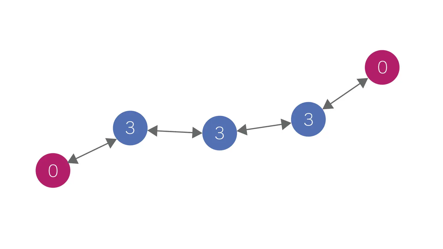
Example of relaying via Role setting
By adding more red devices, communication with up to three relay hops between them can be established.
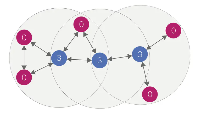
Example of adding transmitters and receivers