Serial Communication App Transparent Mode
External microcontrollers can be easily connected, but to optimize communication using formats, format modes (ASCII / Binary) are suitable.
Overview
Purely wirelesss UART.
| Sending side input | Receiving side output | |
|---|---|---|
| Any data | → | Any data |
Since no format is required, existing UART communication can be easily wirelessized.
However, data delimiters are ambiguous and it is impossible to identify the sender from the receiver output.
The initial state specifies CRLF as the transmission trigger character. Therefore, data input to the transmitter is separated by CRLF, and the data before CRLF is transmitted.
For example, entering Hello<Enter> on the transmitting terminal results in Hello being output on the receiving terminal.
[Sending side]
Hello <- Input
[Receiving side]
Hello <- Output
Continuous input strings are split and sent in chunks of 80 bytes. Data up to the trigger character should normally be 80 bytes or less.
All terminals are considered child devices, and the transmitted content is broadcast. Communication with all terminals is possible, but the destination cannot be specified. Both ASCII characters and binary data can be sent.
Relay supports up to 3 hops. By default, relay is disabled.
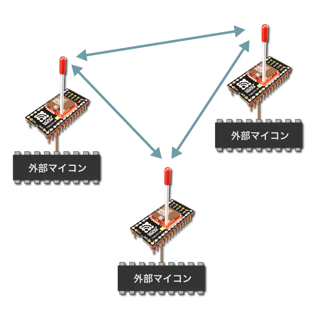
Distinction between Parent and Child Devices
Transparent mode does not distinguish between parent and child devices.
If application ID and frequency channel are the same, data entered into any terminal is sent to other terminals.
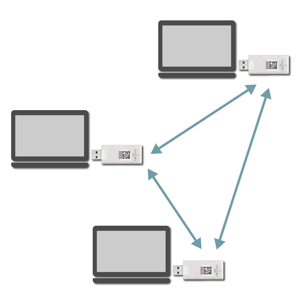
Network configuration image
Identification of Sender
Transparent mode cannot identify the sender.
To identify sender, sender information must be included in data input to the transmitter.
Transmission Trigger
Transmission trigger must be considered, as data is divided and transmitted wirelessly packet by packet.
Therefore, the following transmission triggers must be taken into account:
- When a timeout after data input is reached
- When the input data reaches the minimum data size
- When the transmission trigger character is received
Transmission Trigger Priority
Transmission trigger settings can be specified from the interactive mode k: Transmission Trigger item.
Example Setting
When setting the transmission trigger character to LF, minimum data size to 8 bytes, and timeout to 30 ms, set as follows:
 m: set UART mode (D)
 k: set Tx Trigger (sep=0x0a, min_bytes=8 dly=30[ms])
 o: set option bits (0x00000100)