Pin Assignments of Serial Communication App
TWELITE / TWELITE DIP
The functions of pins used by the Serial Communication App are represented using the pin names from the Super Simple! Standard App Pins shown in the figure below.
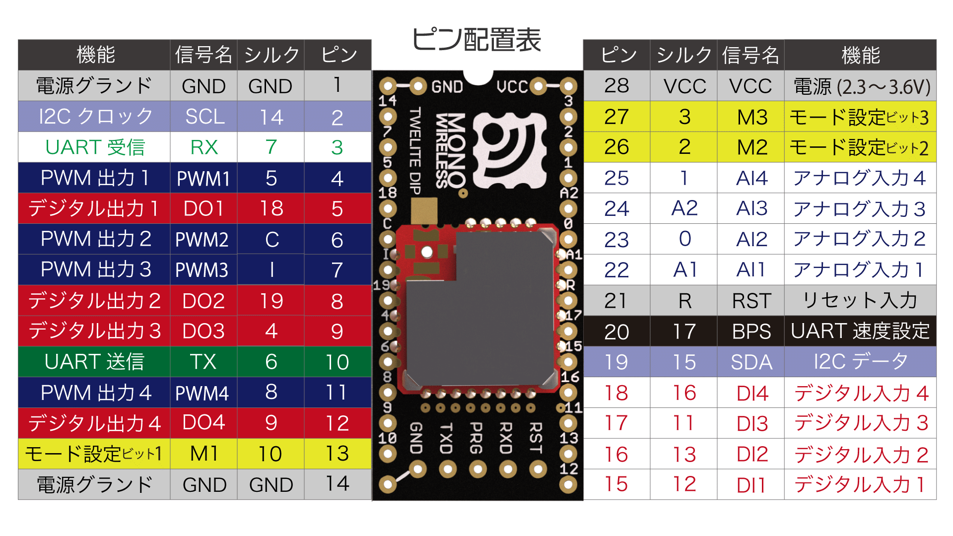
Super Simple! Standard App Pin Assignment Table
| Serial Communication | Super Simple! Standard | Function |
|---|---|---|
VCC GND | VCC GND | Power Input |
TX RX | TX RX | Serial Input and Output |
TX_SUB RX_SUB | SCL SDA | Serial Sub Input and Output |
RTS | PWM1 | Serial Input Permission |
M1 | M1 | Parent/Child Selection |
M2 | M2 | Adding Relay Function to Child |
M3 | M3 | Sleep |
EX1 | AI2 | Overwriting Operation Mode |
BPS | BPS | Enabling Alternative Baud Rate Setting |
RST | RST | Reset Input |
SET | DI1 | Enter interactive mode |
Power Input
Connect a 3.3V (2.0-3.6V) power supply to VCC/GND.
Serial Input and Output
TX/RX are used for transmitting and receiving serial communication (UART).
Serial Sub Input and Output
TX_SUB (SCL) / RX_SUB (SDA) can be used as sub-ports for serial input and output.
Serial Input Permission
When RTS (PWM1) is at Low level, it indicates that serial input to RX is being accepted.
RX when at High level, it is expected to prevent data loss.Parent/Child Selection
Connecting M1 to GND sets the device as a parent, while leaving it open or connecting to VCC sets it as a child.
Setting via Interactive Mode
You can omit this connection and configure it via the interactive mode.
i set Device ID:0
Adding Relay Function to Child
When M2 is connected to GND in child mode, relay functionality can be added.
Setting via Interactive Mode
You can omit this connection and configure it via the interactive mode.
r set Role:1or0x12
Sleep
Connecting M3 to GND puts the device into sleep mode.
Overwriting Operation Mode
By connecting EX1 to GND at startup, the operation mode can be overwritten to format mode (binary).
Enabling Alternative Baud Rate Setting
Connecting BPS to GND enables the alternative baud rate setting specified in interactive mode.
Reset Input
By connecting a push button between RST and GND, a reset button can be implemented. RST has an internal pull-up resistor.
Enter interactive mode
By connection SET to GND on startup, the interactive mode will be ready.
TWELITE UART
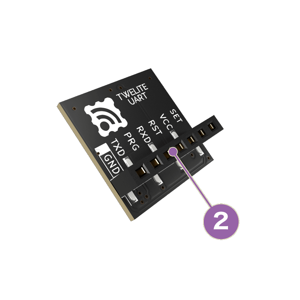
The functions of pins used by the Serial Communication App are represented using the pin names of the 7P interface printed on the board (② in the figure below).
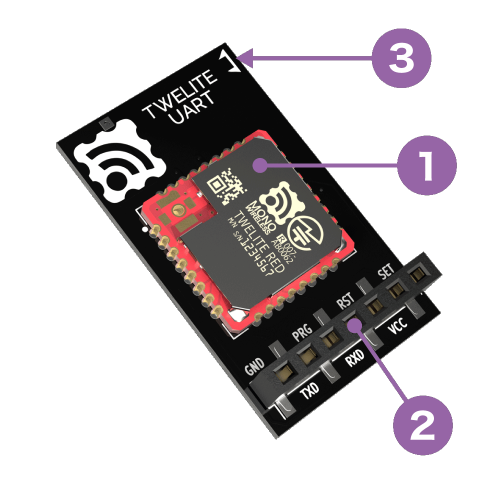
Board Antenna Type
Coaxial Connector Type
| Silkscreen | Function |
|---|---|
VCC GND | Power Input |
TXD RXD | Serial Input and Output |
SET | Overwriting Operation Mode |
RST | Reset Input |
Power Input
Connect a 3.3V (2.0-3.6V) power supply to VCC/GND.
Serial Input and Output
TX/RX are used for transmitting and receiving serial communication (UART).
Overwriting Operation Mode
By connecting SET to GND at startup, the operation mode can be overwritten to format mode (ASCII).
Reset Input
By connecting a push button between RST and GND, a reset button can be implemented. RST has an internal pull-up resistor.