Interactive Mode (Serial Communication App)
This section explains functions specific to the Serial Communication App (App_Uart). For common features, see the TWELITE APPS Manual top page.
Interactive Mode cannot be used while TWELITE is sleeping.
Make sure that the M3 pin is not connected to GND.
Example Display
The following screen will be displayed.
--- CONFIG/TWE UART APP V1-04-5/SID=0x82018ca0/LID=0x78 -- ---
 a: set Application ID (0x67720103)
 i: set Device ID (120=0x78)
 c: set Channels (18)
 x: set RF Conf (3)
 r: set Role (0x0)
 l: set Layer (0x1)
 b: set UART baud (38400)
 B: set UART option (8N1)
 m: set UART mode (E)
 k: set Tx Trigger (sep=0x0d0a, min_bytes=0 dly=0[ms])
 h: set header format [;U;%t;%i;0x%A;%q;%s;<*>;%X;\n]
 C: set crypt mode (0)
 o: set option bits (0x00000100)
---
 S: save Configuration
 R: reset to Defaults
Commands
| Setting Item | Default | Remarks | |
|---|---|---|---|
a | Application ID | 0x67720103 | 32bit |
i | Logical Device ID | 120 | Parent device 0/121, child device 1-100, ID-less child device 120 |
c | Frequency Channel | 18 | 11-26 |
x | Retry count and transmission output | 3 | |
| Retry count | 0 | 1-9 times, 0 disables | |
| Transmission output | 3 | 0-3 | |
r | Role | 0 | Normal 0, relay child 1-3, others |
l | Relay Layer | 0x01 | |
b | UART alternative baud rate | 38400 | Enabled with BPS pin |
B | UART option | 8N1 | |
m | Communication mode | E | A/B/C/D/E |
k | Transmission trigger | 0x0d0a,0,0 | Trigger character, minimum size, timeout |
h | Header / Handle name | Reference | |
| Header | For header transparent mode | ||
| Handle name | For chat mode | ||
C | Encryption | 0 | Disabled 0, AES128bit 1 |
o | Option bits | 0x00000000 | Other detailed settings |
Details of each command are as follows.
a: Application ID
All devices communicating must use the same value. This logically separates networks.
i: Logical Device ID
Set this to distinguish multiple child devices.
If no distinction is necessary or possible, set to 120. If distinction is necessary, child devices should use any value from 1 to 100, and parent devices should be 0 or 121.
c: Frequency Channel
All devices communicating must use the same value. This physically separates networks.
x: Transmission output and retry count
Specify the RF transmission output power and the number of additional packet transmissions in transparent mode and header transparent mode.
r: Role
Valid only for child devices. Specify the following values. Normally select the delivery method that does not use the network layer.
Delivery method not using network layer
0: Normal designation (parent or child)1-3: Relay child (logical device ID is1-100or120). The number1-3indicates the maximum number of relay hops. Since retransmission is repeated up to the maximum relay hops, duplicate packets may be relayed depending on the placement and number of relay devices.
Delivery methods using network layer
Supported only in format mode.
11: Parent12: Relay13: Child
80 to the above values. For example, 93 means “network layer use with silent mode”.l: Relay Layer
The relay layer number. Relay devices attempt to connect to relay devices or parents in upper relay layers (smaller values). Effective only when Role is set to 12.
m: Communication mode
A: Format mode (ASCII)B: Format mode (Binary)C: Chat modeD: Transparent modeE: Header transparent mode
b: UART alternative baud rate
Overrides the alternative baud rate selected when the BPS pin is connected to GND at startup.
Selectable values are 9600/19200/38400/57600/115200/230400. Other values may cause inaccuracies.
If the BPS pin is left open at startup, this setting is not applied. The baud rate is fixed at 115200.
To forcibly apply the alternative baud rate setting ignoring the BPS pin state, enable the option bit Force apply alternative baud rate.
B: UART option
Specify three characters in the order Bit-Parity-Stop.
- Bit
8: 8 Bit7: 7 Bit
- Parity
N: NoneO: OddE: Even
- Stop
1: STOP 12: STOP 2
k: Transmission trigger
Set the transmission trigger applied to input in transparent mode and header transparent mode.
Enter separated by commas , in the following order:
Transmission trigger character
Packets are sent when this character is input (except when the minimum data size is not met).
In Interactive Mode, specify the ASCII code in hexadecimal. The leading 0x is ignored. Default is CRLF.
The transmitted data includes the transmission trigger character. To enable the transmission trigger character, specify option bit 0x00000100 (enabled by default).
Minimum data size
Specify the minimum size of continuous data to be handled. Even if the trigger character is included before reaching the minimum data size, it is invalid.
In Interactive Mode, specify a number between 1 and 80 as byte count. 0 disables. Default is disabled.
Timeout
The wait time until the packet is sent after the last input.
In Interactive Mode, specify a number between 10 and 200 milliseconds. 0 disables. Default is disabled.
When all settings are enabled, the priority order is as follows:
- Timeout
- Minimum data size
- Transmission trigger character
Timeout always takes precedence if set. Even if the trigger character is set, packets are not sent until the minimum data size is reached.
h: Header / Handle name
For header transparent mode, specify the header format; for chat mode, specify the handle name.
Header (header transparent mode)
Specify the header format syntax.
Handle name (chat mode)
Specify the handle name displayed on the counterpart device.
Maximum 23 characters. Consumes the data area (80 bytes) for transmission.
C: Encryption
Specify whether to enable encryption.
Specify 1 to enable AES128bit encryption.
o: Option bits
Specify a 32-bit value. Various settings linked to each bit can be enabled.
| Target bit | Setting item | Default | A | B | C | D | E |
|---|---|---|---|---|---|---|---|
0x00000001 | Disable internal pull-up of M3 | 0️⃣ | ✅ | ✅ | ✅ | ✅ | ✅ |
0x00000002 | Unused | 0️⃣ | |||||
0x00000100 | Enable transmission trigger | 1️⃣ | ✅ | ✅ | |||
0x00000200 | Prioritize new input series | 0️⃣ | ✅ | ✅ | ✅ | ✅ | |
0x00001000 | Disable response message | 0️⃣ | ✅ | ✅ | ✅ | ||
0x00004000 | Loosen duplicate checker | 0️⃣ | ✅ | ✅ | ✅ | ✅ | ✅ |
0x00010000 | Force apply alternative baud rate | 0️⃣ | ✅ | ✅ | ✅ | ✅ | ✅ |
0x00020000 | Simultaneous output to secondary port | 0️⃣ | ✅ | ✅ | ✅ | ✅ | ✅ |
0x00040000 | Switch main port | 0️⃣ | ✅ | ✅ | ✅ | ✅ | ✅ |
0x00100000 | Limit relay layer | 0️⃣ | ❗ | ❗ |
Details of Option Bits
Explanation of settings linked to each bit of the option bit value.
00000001: Disable internal pull-up of M3
Disables the internal pull-up of the M3 pin used for sleep setting on TWELITE DIP.
00000100: Enable transmission trigger
Enables the transmission trigger setting in transparent mode or header transparent mode.
00000200: Prioritize new input series
In format modes (ASCII/Binary), transparent mode, and header transparent mode, prioritize new input series if multiple series are input before transmission completes.
00001000: Disable response message
In format modes (ASCII/Binary) and header transparent mode, disables response messages after transmission completes.
00004000: Loosen duplicate checker
Loosens the duplicate checker conditions on the receiving side.
The duplicate checker eliminates packets duplicated by relaying.
If sending intervals are short (e.g., less than 100ms), different packets may be mistakenly considered identical (including those with different sequence numbers).
Enable this setting when setting short sending intervals or using many transmitters simultaneously.
00010000: Force apply alternative baud rate
Applies the alternative baud rate setting even if the BPS pin input is not Low at startup.
00020000: Simultaneous output to secondary port
Outputs the serial output TX also to the serial secondary output TX_SUB.
00040000: Switch main port
Swaps the serial input/output TX/RX with the serial secondary input/output TX_SUB/RX_SUB.
00100000: Limit relay layer
In format modes (ASCII/Binary), when specifying delivery methods using network layer, always send to relay devices or parent devices one layer above. Normally, delivery methods using network layer send to the relay or parent device with the best radio quality in the upper layer.
About Relay Function
When communication distance is insufficient or there are obstacles preventing communication, using relay devices is useful.
Devices with relay function retransmit packets they receive to other devices.
Relay Function Settings
Normally, change the Role value to 1-3 while in Interactive Mode. The default value is 0, which does not have relay function.
r: set Role (0x0)
The number 1-3 indicates the maximum number of relay hops. For example, specifying 3 allows up to 3 relay hops.
Distinction between parent and child devices applies only to child devices.
Setting Example
The following network configuration shows devices with red color set to Role 0 and devices with blue color set to Role 3.
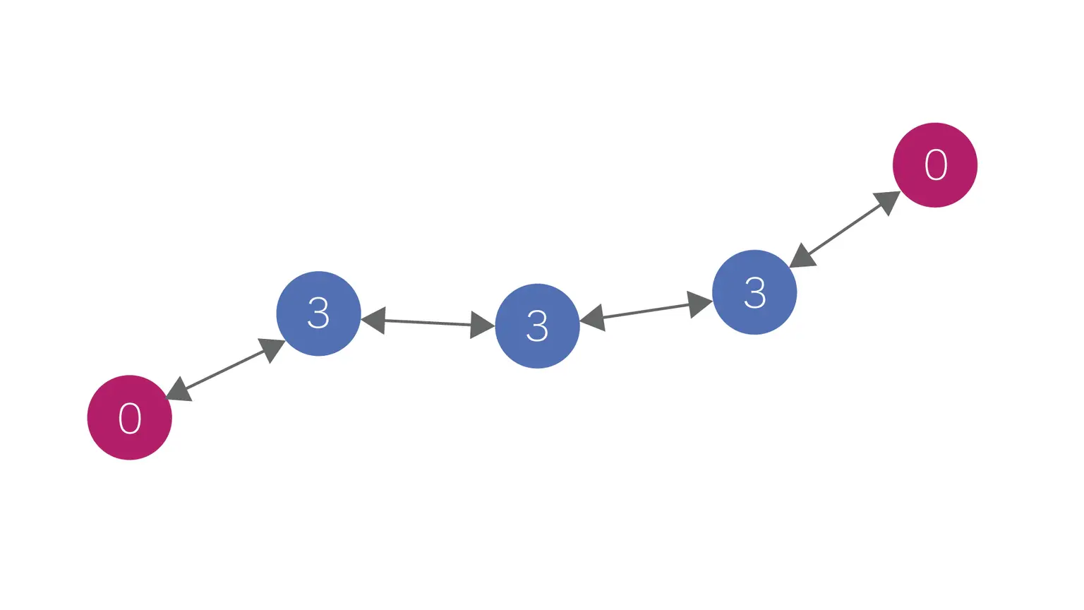
Example of relay by role setting
Adding red devices allows communication with up to 3 relay hops between red devices.
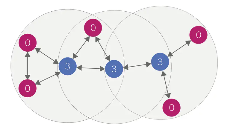
Example of adding transmitters and receivers