0xDB Command in Serial Communication App Format Mode (ASCII)
Setting functions using the 0xDB command in format mode (ASCII) without using Interactive Mode
When data formatted in a specific manner is input on the transmitting side, the receiving side outputs data formatted in the same manner.
Data is represented as hexadecimal ASCII strings.
| Transmitting Side Input | Receiving Side Output | |
|---|---|---|
| Simple/Extended format data | → | Simple/Extended format data |
SET pin connected to GND.EX1 pin connected to GND.There are two types of formats that can be handled.
For example, 5-byte binary data 0x48 0x45 0x4C 0x4C 0x4F can be sent using the simple format as follows.
[Sending side]
:000148454C4C4F8B  <- Input
:DBA1800103  <- Output
[Receiving side]
:780148454C4C4F13 <- Output
When sending data sequences expressed in basic or extended formats, they are converted to ASCII strings (0-9, A-F).
The format is extremely simple! It starts with : and ends with CRLF, just like the output of the standard app (App_Twelite) or the parent device output of the parent/repeater app (App_Wings).
| Header | Payload | Checksum | Footer |
|---|---|---|---|
: | Repeated 00-FF | LRC8 of payload | CRLF |
: (0x3A)\r\n/0x0D 0x0A)For example, binary data 0x00 0x11 0x22 0x33 0xAA 0xBB 0xCC is expressed as follows.
:00112233AABBCC69<CR><LF>
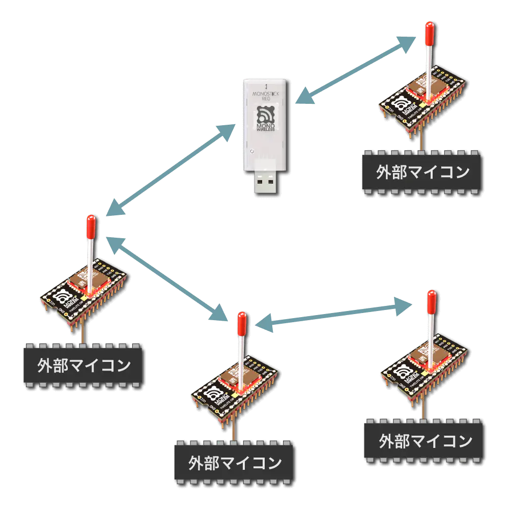
Format mode distinguishes between parent and child devices.
The Application ID and frequency channel must be matched between parent and child devices.
Format mode allows identifying the source from the received data.
The simple format uses the Logical Device ID, and the extended format uses the Logical Device ID plus the extended address.
0x8 added at the front.When using the simple format of format mode, follow the format below.
| # | Data | Description | Notes |
|---|---|---|---|
char | Header | Only : | |
| 0 | uint8 | Destination Logical Device ID | Parent 0x00, child 0x01-0x64, all children 0x78 |
| 1 | uint8 | Command number | Any value less than 0x80 |
| 2 | [uint8] | Arbitrary data | Byte sequence of length (N) (recommended (N \leqq 80)) |
uint8 | Checksum | LRC8 | |
char | Footer | CR (0x0D/'\r') | |
char | Footer | LF (0x0A/'\n') |
0x01 command of the Extremely Simple! Standard App.| # | Data | Description | Notes |
|---|---|---|---|
char | Header | Only : | |
| 0 | uint8 | Source Logical Device ID | Parent 0x00, child 0x01-0x64, unset child 0x78 |
| 1 | uint8 | Command number | Value less than 0x80 specified by the sender |
| 2 | [uint8] | Arbitrary data | Byte sequence of length (N) |
uint8 | Checksum | LRC8 | |
char | Footer | CR (0x0D/'\r') | |
char | Footer | LF (0x0A/'\n') |
0x01 command of the Extremely Simple! Standard App.| # | Data | Description | Notes |
|---|---|---|---|
char | Header | Only : | |
| 0 | uint8 | Source Logical Device ID | Only 0xDB: indicates itself |
| 1 | uint8 | Command number | Only 0xA1 |
| 2 | uint8 | Response ID | Continuation number in the range 128-255 (0x80-0xFF) |
| 3 | uint8 | Result | Success 1, failure 0 |
uint8 | Checksum | LRC8 | |
char | Footer | CR (0x0D/'\r') | |
char | Footer | LF (0x0A/'\n') |
An example of sending byte sequence 0x11 0x22 0x33 0xAA 0xBB 0xCC from the parent to all children is shown.
[Sending side: Parent]
:7801112233AABBCCF0<CR><LF>  <- Input
:DBA1800103<CR><LF>  <- Output
The trailing
0xF0is the checksum: the two’s complement of the sum from0x78to0xCC(LSB 8 bits).
[Receiving side: All children]
:0001112233AABBCC68<CR><LF> <- Output
The trailing
0x68is the checksum: the two’s complement of the sum from0x00to0xCC(LSB 8 bits).
When using the extended format of format mode, follow the format below.
| # | Data | Description | Notes |
|---|---|---|---|
char | Header | Only : | |
| 0 | uint8 | Destination Logical Device ID | Parent 0x00, child 0x01-0x64, all children 0x78 |
| 1 | uint8 | Command number | Only 0xA0 |
| 2 | uint8 | Response ID | Any value |
| 3 | [uint8] | Options | Option list of length (N) (Details of option list) |
| 3+(N) | [uint8] | Arbitrary data | Byte sequence of length (M) (recommended (M \leqq 80)) |
uint8 | Checksum | LRC8 | |
char | Footer | CR (0x0D/'\r') | |
char | Footer | LF (0x0A/'\n') |
| # | Data | Description | Notes |
|---|---|---|---|
char | Header | Only : | |
| 0 | uint8 | Extended Address Specifier | Only 0x80 |
| 1 | uint8 | Command number | Only 0xA0 |
| 2 | uint8 | Response ID | Any value |
| 3 | uint32 | Destination Extended Address | Serial ID with 0x8 added at the front |
| 7 | [uint8] | Options | Option list of length (N) (Details of option list) |
| 7+(N) | [uint8] | Arbitrary data | Byte sequence of length (M) (recommended (M \leqq 80)) |
uint8 | Checksum | LRC8 | |
char | Footer | CR (0x0D/'\r') | |
char | Footer | LF (0x0A/'\n') |
In the extended format, you can specify fine settings by specifying the option list.
The option list is represented by repeating option IDs and their arguments. The end is 0xFF.
0xFF.| ID | Argument | Default | Description |
|---|---|---|---|
0x01 | None | Disabled | Enable MAC ACK |
0x02 | uint8 | 0x00 | Enable application retry |
0x03 | uint16 | 0x0000 | Minimum initial transmission delay |
0x04 | uint16 | 0x0000 | Maximum initial transmission delay |
0x05 | uint16 | 10 | Application retry interval |
0x06 | None | Disabled | Allow parallel requests |
0x07 | None | Disabled | Disable response messages |
0x08 | None | Disabled | Sleep after transmission |
0x01: Enable MAC ACKEnables MAC layer ACK (acknowledgment).
Not suitable for frequent data transmission, but can improve reliability.
0x78).0x02: Enable Application RetryWhen using MAC ACK, specify 0x00-0x0F. Retries 0-16 times respectively until the transmission succeeds.
When not using MAC ACK, specify 0x81-0x8F. Always retries 1-16 times.
Response messages are output after all retries are completed.
0x03: Minimum Initial Transmission DelaySpecifies the minimum delay before the first transmission in milliseconds.
0x04: Maximum Initial Transmission DelaySpecifies the maximum delay before the first transmission in milliseconds.
0x05: Application Retry IntervalSpecifies the retry interval in milliseconds when application retry is enabled.
0x06: Allow Parallel RequestsAllows parallel requests.
When allowed, the next request can be accepted without blocking until the current request completes.
For example, if three requests with a 0.5-second delay are input consecutively, normally they are processed sequentially at 0.5s, 1.0s, and 1.5s. When parallel requests are allowed, they are processed in no particular order after 0.5s. Note that it cannot be used when packet fragmentation is required.
0x07: Disable Response MessagesDisables the response messages output when data is input on the transmitting side.
0x08: Sleep After TransmissionImmediately puts the device to sleep after transmission.
When RX detects a rising edge, it wakes up from sleep. Please input any 1 byte of data.
After waking up, UART initialization completes and input is accepted.
| # | Data | Description | Notes |
|---|---|---|---|
char | Header | Only : | |
| 0 | uint8 | Source Logical Device ID | Parent 0x00, child 0x01-0x64, unset child 0x78 |
| 1 | uint8 | Command number | Only 0xA0 |
| 2 | uint8 | Response ID | Value specified by the sender |
| 3 | uint32 | Source Extended Address | Serial ID with 0x8 added at the front |
| 7 | uint32 | Destination Extended Address | 0xFFFFFFFF if using Logical Device ID |
| 11 | uint8 | LQI | Radio communication quality at reception |
| 12 | uint16 | Length of following byte sequence | Number of bytes (M) |
| 14 | [uint8] | Arbitrary data | Byte sequence of length (M) |
uint8 | Checksum | LRC8 | |
char | Footer | CR (0x0D/'\r') | |
char | Footer | LF (0x0A/'\n') |
| # | Data | Description | Notes |
|---|---|---|---|
char | Header | Only : | |
| 0 | uint8 | Source Logical Device ID | Only 0xDB: indicates itself |
| 1 | uint8 | Command number | Only 0xA1 |
| 2 | uint8 | Response ID | Value specified at input |
| 3 | uint8 | Result | Success 1, failure 0 |
uint8 | Checksum | LRC8 | |
char | Footer | CR (0x0D/'\r') | |
char | Footer | LF (0x0A/'\n') |
An example of sending byte sequence 0x11 0x22 0x33 0xAA 0xBB 0xCC from the parent to a child is shown.
An example sending from the parent to the child with Logical Device ID 0x42.
0x010x81000000 (Serial ID 0x1000000)[Sending side: Parent]
:42A001FF112233AABBCC87<CR><LF>  <- Input
:DBA1010182<CR><LF>  <- Output
The trailing
0x87is the checksum: the two’s complement of the sum from0x42to0xCC(LSB 8 bits).
[Receiving side: Child]
:00A00181000000FFFFFFFFC80006112233AABBCC7D<CR><LF> <- Output
The trailing
0x7Dis the checksum: the two’s complement of the sum from0x00to0xCC(LSB 8 bits).
An example sending from the parent to the child with extended address 0x81000001 (Serial ID 0x1000001).
0x010x81000000 (Serial ID 0x1000000)[Sending side: Parent]
:80A00181000001FF112233AABBCCC7<CR><LF>  <- Input
:DBA1010182<CR><LF>  <- Output
The trailing
0xC7is the checksum: the two’s complement of the sum from0x80to0xCC(LSB 8 bits).
[Receiving side: Child]
:00A0018100000081000001C80006112233AABBCCF7<CR><LF> <- Output
The trailing
0xF7is the checksum: the two’s complement of the sum from0x00to0xCC(LSB 8 bits).
An example sending from the parent to the child with Logical Device ID 0x42 using MAC ACK.
0x010x01: Enable MAC ACK specified0x81000000 (Serial ID 0x1000000)[Sending side: Parent]
:42A00101FF112233AABBCC86<CR><LF>  <- Input
:DBA1010182<CR><LF>  <- Output
The trailing
0x86is the checksum: the two’s complement of the sum from0x42to0xCC(LSB 8 bits).
[Receiving side: Child]
:00A00181000000FFFFFFFFC80006112233AABBCC7D<CR><LF> <- Output
The trailing
0x7Dis the checksum: the two’s complement of the sum from0x00to0xCC(LSB 8 bits).
An example sending from the parent to the child with Logical Device ID 0x42 with a 768ms delay.
0x010x03: Minimum initial transmission delay specified0x81000000 (Serial ID 0x1000000)[Sending side: Parent]
:42A001030300FF112233AABBCC81<CR><LF>  <- Input
:DBA1010182<CR><LF>  <- Output
The trailing
0x81is the checksum: the two’s complement of the sum from0x42to0xCC(LSB 8 bits).
[Receiving side: Child]
:00A00181000000FFFFFFFFC80006112233AABBCC7D<CR><LF> <- Output
The trailing
0x7Dis the checksum: the two’s complement of the sum from0x00to0xCC(LSB 8 bits).
0xDB CommandInstead of setting interactive mode, you can operate and configure the module by inputting the 0xDB command from UART.
Setting functions using the 0xDB command in format mode (ASCII) without using Interactive Mode