Serial Communication App Header Transparent Mode
Overview
Enabled by default.
When arbitrary data is input to the transmitting terminal, the receiving terminal outputs data with auxiliary information in a specific format.
| Transmitting side input | Receiving side output | |
|---|---|---|
| Any data | → | Any data + auxiliary info |
By default, data input on the transmitting side is separated by CRLF and data before CRLF is sent.
For example, entering Hello<Enter> on the transmitting side results in output Hello with auxiliary info on the receiving side. The transmitting side also outputs a message indicating transmission completion.
[Transmitting side]
Hello  <- input
;U;00004;219;0x820163B2;000;000;0,1,Hel...;6E;  <- output
[Receiving side]
;U;00003;000;0x820163B2;255;000;Hello;42; <- output
The auxiliary information output by the receiving side includes the source address, received signal strength, checksum, etc. The format of the auxiliary information can be customized.
Distinction between Parent and Child Devices
Header Transparent Mode does not distinguish between parent and child devices.
If the Application ID and frequency channel are the same, data input to any terminal is sent to other terminals.
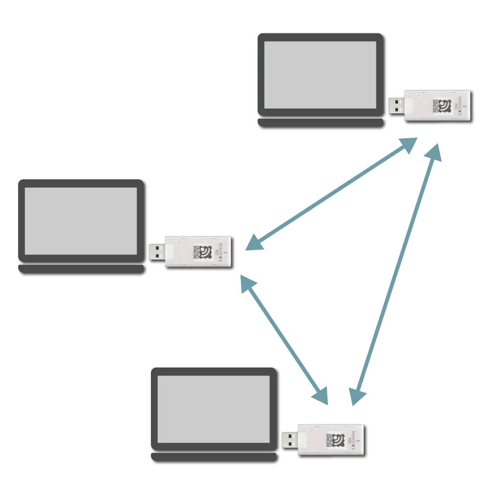
Network configuration image
Identification of Source
The header on the received data includes the logical device ID and serial ID of the sender.
Output Format on Receiving Side
The output format is represented as semicolon (;) separated fields.
[Example output in default state]
;U;00777;120;0x81025A17;120;013;HELLO;79;
This output can be interpreted as follows.
| Data | Description | Value | |
|---|---|---|---|
U | char | Fixed value | U |
00777 | uint16 | Timestamp at output | 777 seconds |
120 | uint8 | Source logical device ID | 120 ID-less child device |
0x81025A17 | uint32 | Source extended address | 81025A17 |
120 | uint8 | LQI (link quality indicator) | 120/255 |
013 | uint8 | Source sequence number | 13 |
HELLO | [uint8] | Input data | HELLO |
79 | uint8 | XOR checksum | 0x79 |
The source logical device ID is 219 for its own response message.
The extended address is the 7-bit serial ID printed on the TWELITE device with a leading 0x8 added.
Customization by Header Format
The output format on the receiving side follows the header format.
Changing the header format customizes the content of the auxiliary information output and the checksum calculation range.
;U;%t;%i;0x%A;%q;%s;<*;%X;\n.The header format can be changed via the interactive mode command h: set header format.
Simplest Format
The simplest header format is *\n. It outputs the received data with CRLF line endings.
h: set header format [*\n]
When sending HELLO in this case, it behaves as follows.
[Receiving side]
HELLO<CR><LF> or HELLO<LF>
[Transmitting side]
HELLO<CR><LF>
Special Characters in Header Format
You can customize the output by including the following special characters in the header format.
General
| Description | |
|---|---|
* | Received data |
&hl | Arbitrary ASCII character (e.g., &20 is space) |
< | Start position for checksum calculation (default is start of string) |
> | End position for checksum calculation (only from v1.4.6) |
Characters following \ (backslash)
| Description | |
|---|---|
\n | CRLF (0x0D 0x0A) |
\t | TAB |
\* | * |
\% | % |
\< | < |
\> | > |
\& | & |
Characters following %
| Description | Length | Data format | |
|---|---|---|---|
%A | Source address (32bit) | 8 chars | Hexadecimal |
%a | Source address (32bit) | 10 chars | Hexadecimal |
%I | Source logical address (8bit) | 2 chars | Hexadecimal |
%i | Source logical address (8bit) | 3 chars | Decimal |
%T | Current system time (seconds) | 4 chars | Hexadecimal |
%t | Current system time (seconds) | 5 chars | Decimal |
%S | Source sequence number (hex) | 2 chars | Hexadecimal |
%s | Source sequence number (hex) | 3 chars | Hexadecimal |
%Q | Received signal strength | 2 chars | Hexadecimal |
%q | Received signal strength | 3 chars | Decimal |
%X | Checksum | 2 chars | Hexadecimal |
%x | Checksum | 3 chars | Decimal |
Checksum Calculation
The checksum is calculated by XOR (exclusive OR) from the start of the data or from the position indicated by < in the header format up to just before %X or %x.
Example in Default State
The default header format is ;U;%t;%i;0x%A;%q;%s;<*;%X;\n, where the checksum calculation range is *;.
That is, when sending HELLO, the binary data HELLO; is targeted, resulting in checksum 0x79.
[Verification code in Python]
from functools import reduce

def main():
    data = "HELLO;"
    checksum = reduce(lambda x, y: x ^ y, data.encode("ascii"))
    print(f"{data} -> {hex(checksum)}")

if __name__ == "__main__":
   main()  # HELLO; -> 0x79
Other Examples
For example, consider the header format ;%I;*;%X.
Since < is not specified, the checksum calculation range is ;%I;*;.
That is, when sending HELLO, the binary data ;000;HELLO; is targeted, resulting in checksum 0x49.
[Verification code in Python]
from functools import reduce

def main():
    data = ";000;HELLO;"
    checksum = reduce(lambda x, y: x ^ y, data.encode("ascii"))
    print(f"{data} -> {hex(checksum)}")

if __name__ == "__main__":
   main()  # ;000;HELLO; -> 0x49
Transmission Trigger
There is no format on the transmitting side input, but data is split and transmitted packet by packet.
Therefore, the following transmission triggers must be considered.
- When timeout after data input occurs
- When input data reaches the minimum data size
- When a transmission trigger character is received
Priority of Transmission Triggers
Transmission trigger settings are specified via the interactive mode k: set transmission trigger item.
Example Setting
To set the transmission trigger character to LF, minimum data size to 8 bytes, and timeout to 30 ms, use the following settings.
 m: set UART mode (E)
 k: set Tx Trigger (sep=0x0a, min_bytes=8 dly=30[ms])
 o: set option bits (0x00000100)