This is the multi-page printable view of this section. Click here to print...

Return to the regular view of this page

As of 2025-07-24

Parent and Repeater App Manual

v1.2.1 BLUE/RED Stable version
Acts as parent or repeater for child devices of TWELITE APPS and act.

Features

Can process all data packets of TWELITE APPS and act, and can be used as common parent or repeater.

  • Collect data from multiple TWELITE APPS and act such as Extremely Simple! Standard App and Pal App with one MONOSTICK.
  • Can operate multiple systems separately on 16 channels.
  • By setting application ID, multiple systems can coexist on the same channel.
  • Communication range extension with repeater function.

1 - Operating Modes of Parent and Repeater App

Operating modes of Parent and Repeater App

There are two modes: Parent mode and Repeater mode.

1.1 - Parent Mode of Parent and Repeater App

Receives data from child devices and sends data to child devices

Receives data sent from child devices and outputs it via the serial port. Also sends commands input from the serial port to child devices.

1.1.1 - Messages of Parent and Repeater Apps

Output when data is received from child devices

Receives data sent from child devices and outputs it from the serial port in a predefined format.

1.1.1.1 - Output from the Extremely Simple! Standard App (Parent and Repeater App)

Output format when receiving data from the Extremely Simple! Standard App

0x81: Status Notification from the Peer Device

Outputs the status of the received input signals.

Data Format

#DataDescriptionNotes
charHeaderOnly :
0uint8Logical Device ID of Sender
1uint8Command NumberOnly 0x81
2uint8Packet IdentifierGenerated from Application ID
3uint8Protocol VersionOnly 0x01
4uint8LQI0-255
5uint32Serial ID of Sender0x8???????
9uint8Logical Device ID of Receiver
10uint16Timestamp64 counts per second
12uint8Number of Relays
13uint16Power Supply VoltageUnit: mV
15int8-(Unused)
16uint8Digital SignalsCorresponds to DIx from LSB upwards, 0 means High
If MSB is 1, periodic transmission
17uint8Digital Signal MaskCorresponds to DIx from LSB upwards, 1 means valid
18uint8Converted Value of AI1See Calculation of Analog Signals, 0xFF means unused
19uint8Converted Value of AI2See Calculation of Analog Signals, 0xFF means unused
20uint8Converted Value of AI3See Calculation of Analog Signals, 0xFF means unused
21uint8Converted Value of AI4See Calculation of Analog Signals, 0xFF means unused
22uint8Correction Value of AIxCorresponds to AIx in 2-bit increments from LSB upwards
uint8ChecksumLRC8
charFooterCR (0x0D/'\r')
charFooterLF (0x0A/'\n')

Calculation of Analog Signals

The input voltage \(V\) of AIx can be expressed by the received converted value \(e_{r}\) and the correction value \(e_{fr}\) as follows:

$$\begin{align*} V &= e+e_f \\ \text{where} \\ e &= 16e_r \\ e_f &= 4e_{fr} \\ \end{align*}$$

The unit is mV

Example of Output Data

:78811501C98201015A000391000C2E00810301FFFFFFFFFB
#DataDescriptionValue
:charHeader:
780uint8Logical Device ID of Sender0x78
811uint8Command Number0x81
152uint8Packet Identifier0x15
013uint8Protocol Version0x01
C94uint8LQI201/255
8201015A5uint32Serial ID of Sender0x201015A
009uint8Logical Device ID of Receiver0x00
039110uint16TimestampApprox. 14.27 seconds
0012uint8Number of Relays0
0C2E13uint16Power Supply Voltage3118 mV
0015int8-
8116uint8Digital SignalsDI1 L DI2 H
DI3 H DI4 H
(Periodic transmission)
0317uint8Digital Signal MaskDI1 DI2
0118uint8Converted Value of AI116 mV
FF19uint8Converted Value of AI2Unused
FF20uint8Converted Value of AI3Unused
FF21uint8Converted Value of AI4Unused
FF22uint8Correction Value of AIxAI1 0x03
FBuint8Checksum0xFB
charFooter\r
charFooter\n

Data Identification Conditions

The parent and relay apps can receive data from various types of child devices.

To confirm whether the output data is from the Extremely Simple! Standard App, refer to the following:

#DataItemCondition
1uint8Command NumberMust be 0x81
3uint8Protocol VersionMust be 0x01
5uint32Serial ID of SenderMSB must be 1 (i.e., 0x8???????)
--Payload SizeMust be 23 bytes (between : and checksum)

Parser Implementation Examples

0x01: Reception of Arbitrary Data

Data Format

#DataDescriptionNotes
charHeaderOnly :
0uint8Logical Device ID of SenderParent 0x00, Child 0x01-0x64, Unset Child 0x78
1uint8Command NumberOnly 0x01
2[uint8]Arbitrary DataByte array of length \(N\)
uint8ChecksumLRC8
charFooterCR (0x0D/'\r')
charFooterLF (0x0A/'\n')

1.1.1.2 - Output from Remote Control App (Parent and Repeater App)

Output format when data is received from the Remote Control App

0x81: Status Notification from Remote Device

Outputs the state of the received input signal.

Data Format

#DataDescriptionRemarks
charHeader: only
0uint8Source Logical Device ID
1uint8Command NumberOnly 0x81
2uint8Packet IdentifierOnly 0x0F
3uint8Protocol VersionOnly 0x01
4uint8LQI0-255
5uint32Source Serial ID0x8???????
9uint8Destination Logical Device ID
10uint16Timestamp64 counts per second, MSB is internal flag
12uint8Relay Count
13uint16Digital SignalCorresponds to Ix from LSB, 0 is High
15uint16Digital Signal MaskCorresponds to Ix from LSB, 1 means enabled
17uint16Digital Signal FlagCorresponds to Ix from LSB, 1 means interrupt triggered
19uint8UnusedInternal management
uint8ChecksumLRC8
charFooterCR (0x0D/\r)
charFooterLF (0x0A/\n)

Example of Output Data

:01810F01DB8630000200645F000040004F00400049
#DataDescriptionValue
:charHeader:
010uint8Source Logical Device ID0x78
811uint8Command Number0x81
0F2uint8Packet Identifier0x15
013uint8Protocol Version0x01
DB4uint8LQI219/255
863000025uint32Source Serial ID0x6300002
009uint8Destination Logical Device ID0x00
645F10uint16TimestampAbout 401 seconds
0012uint8Relay Count0
004013uint16Digital SignalI7 is Low
004F15uint16Digital Signal MaskI7, I1-I4 are enabled
004017uint16Digital Signal FlagI7 has changed due to interrupt
0019uint8Unused
49uint8Checksum0x49
charFooter\r
charFooter\n

Data Identification Conditions

Parent and Repeater App can receive data from various types of child devices.

To confirm that the output data is from the Remote Control App, refer to the following conditions.

#DataItemCondition
1uint8Command NumberMust be 0x81
3uint8Protocol VersionMust be 0x02
5uint32Source Serial IDMSB must be 1 (0x8???????)
--Payload SizeMust be 20 bytes (between : and checksum)

Example Parser Implementations

1.1.1.3 - Output from Serial Communication App (Parent and Repeater App)

Output format when receiving data from the serial communication app

Format Mode: Simple Format

Data Format

#DataDescriptionNotes
charHeaderOnly :
0uint8Logical device ID of senderParent 0x00, child 0x01-0x64, unassigned child 0x78
1uint8Command numberValue less than 0x80 specified by sender
2[uint8]Arbitrary dataByte array of length (N)
uint8ChecksumLRC8
charFooterCR (0x0D/'\r')
charFooterLF (0x0A/'\n')

Example of Output Data

:780100112233AABBCCDD13
#DataDescriptionValue
:charHeader:
780uint8Logical device ID of senderUnassigned child ID
011uint8Command number0x01
00112233AABBCCDD2[uint8]Arbitrary dataAs is
13uint8Checksum0x13
charFooter\r
charFooter\n

Conditions to Identify Data

The Parent and Repeater App can receive data from various types of child devices.

To verify whether the output data is from the serial communication app (format mode: simple format), refer to the following:

#DataItemCondition
0uint8Logical device ID of senderMust be less than or equal to 0x64 or equal to 0x78
1uint8Command numberMust be less than 0x80
--Payload sizeMust be between 3 and 82 bytes

Example Implementation of Parser

Format Mode: Extended Format

Data Format

#DataDescriptionNotes
charHeaderOnly :
0uint8Logical device ID of senderParent 0x00, child 0x01-0x64, unassigned child 0x78
1uint8Command numberOnly 0xA0
2uint8Response IDValue specified by sender
3uint32Extended address of senderValue with 0x8 added at the start of serial ID
7uint32Extended address of receiver0xFFFFFFFF when logical device ID is used
11uint8LQIRadio communication quality at reception
12uint16Length of following byte arrayNumber of bytes (M)
14[uint8]Arbitrary dataByte array of length (M)
uint8ChecksumLRC8
charFooterCR (0x0D/'\r')
charFooterLF (0x0A/'\n')

Example of Output Data

:78A0028201015AFFFFFFFFA8000700112233AABBCCC6
#DataDescriptionNotes
:charHeader:
780uint8Logical device ID of senderUnassigned child ID
A01uint8Command number0xA0
022uint8Response ID0x02
8201015A3uint32Extended address of sender0x201015A
FFFFFFFF7uint32Extended address of receiverLogical device ID specified
A811uint8LQI168/255
000712uint16Length of following byte array7 bytes
00112233AABBCC14[uint8]Arbitrary dataAs is
C6uint8Checksum0xC6
charFooter
charFooter

Conditions to Identify Data

The Parent and Repeater App can receive data from various types of child devices.

To verify whether the output data is from the serial communication app (format mode: extended format), refer to the following:

#DataItemCondition
0uint8Logical device ID of senderMust be less than or equal to 0x64 or equal to 0x78
1uint8Command numberMust be 0xA0
2uint8Response IDMust be less than 0x80
3uint32Extended address of senderMSB must be 1 (i.e., 0x8???????)
12uint16Length of following byte arrayMust be payload size - 14 bytes

Example Implementation of Parser

1.1.1.4 - Output from Pal/Cue/Aria Apps (Parent and Repeater App)

Output format when data is received from Pal, Cue, and Aria apps

1.1.1.4.1 - Output from PAL App (Parent and Repeater App)

Output format when data is received from the PAL App

General

Data received from the PAL App is represented as a series of sensor data consisting of sensor type and its value.

Below are specific examples according to the product type.

Open/Close Sensor PAL

Data Format

#DataDescriptionRemarks
charHeaderOnly :
0uint32Serial ID of repeater80000000 if no repeater
4uint8LQI0-255
5uint16Sequence number
7uint32Serial ID of sender0x8???????
11uint8Logical device ID of sender
12uint8Sensor typeOnly 0x80
13uint8PAL board version and PAL board IDOnly 0x81
14uint8Number of sensor dataOnly 3
Sensor data 1
15uint8Info bitsOnly 0x11
16uint8Data sourceOnly 0x30
17uint8Extended byteOnly 0x08
18uint8Data lengthOnly 2
19uint16DataPower supply voltage (mV)
Sensor data 2
21uint8Info bitsOnly 0x11
22uint8Data sourceOnly 0x30
23uint8Extended byteOnly 0x01
24uint8Data lengthOnly 2
25uint16DataADC1 voltage (mV)
Sensor data 3
27uint8Info bitsOnly 0x00
28uint8Data sourceOnly 0x00
29uint8Extended byteOnly 0x00
30uint8Data lengthOnly 1
31uint8DataMagnetic data
End of sensor data
32uint8Checksum 1CRC8 up to this point
uint8Checksum 2LRC8 up to checksum 1
charFooterCR (0x0D/'\r')
charFooterLF (0x0A/'\n')

Example Output Data

:80000000A8001C82012B1E01808103113008020D0C1130010203E40000000101EC6E
#DataDescriptionValue
:charHeader:
800000000uint32Serial ID of repeaterNo repeater
A84uint8LQI168/255
001C5uint16Sequence number28
82012B1E7uint32Serial ID of sender0x2012B1E
0111uint8Logical device ID of sender0x01
8012uint8Sensor type
8113uint8PAL board version and PAL board IDOpen/Close PAL V1
0314uint8Number of sensor data3
Sensor data 1
1115uint8Info bitsWith extended byte uint16
3016uint8Data sourceVoltage
0817uint8Extended bytePower supply
0218uint8Data length2 bytes
0D0C19uint16Data3340mV
Sensor data 2
1121uint8Info bitsWith extended byte uint16
3022uint8Data sourceVoltage
0123uint8Extended byteADC1
0224uint8Data length2 bytes
03E425uint16Data996mV
Sensor data 3
0027uint8Info bitsNo extended byte uint8
0028uint8Data sourceMagnetic
0029uint8Extended byteNone
0130uint8Data length1 byte
0131uint8DataN pole approached
End of sensor data
EC32uint8Checksum 10xEC
6Euint8Checksum 20x6E
charFooter'\r'
charFooter'\n'

Data Identification Criteria

The Parent and Repeater App can receive data from various types of child devices.

To check whether the output data is from the PAL App (Open/Close Sensor PAL), refer to the following points.

#DataItemCondition
0uint32Serial ID of repeaterMSB is 1
7uint32Serial ID of senderMSB is 1
12uint8Sensor typeMust be 0x80
13uint8PAL board version and IDMust be 0x81
--Payload size33 bytes

Example Parser Implementations

Environmental Sensor PAL

Data Format

#DataDescriptionRemarks
charHeaderOnly :
0uint32Serial ID of repeater80000000 if no repeater
4uint8LQI0-255
5uint16Sequence number
7uint32Serial ID of sender0x8???????
11uint8Logical device ID of sender
12uint8Sensor typeOnly 0x80
13uint8PAL board version and PAL board IDOnly 0x82
14uint8Number of sensor dataOnly 5
Sensor data 1
15uint8Info bitsOnly 0x11
16uint8Data sourceOnly 0x30
17uint8Extended byteOnly 0x08
18uint8Data lengthOnly 2
19uint16DataPower supply voltage (mV)
Sensor data 2
21uint8Info bitsOnly 0x11
22uint8Data sourceOnly 0x30
23uint8Extended byteOnly 0x01
24uint8Data lengthOnly 2
25uint16DataADC1 voltage (mV)
Sensor data 3
27uint8Info bitsOnly 0x05
28uint8Data sourceOnly 0x01
29uint8Extended byteOnly 0x00
30uint8Data lengthOnly 2
31int16DataTemperature data
Sensor data 4
33uint8Info bitsOnly 0x01
34uint8Data sourceOnly 0x02
35uint8Extended byteOnly 0x00
36uint8Data lengthOnly 2
37uint16DataHumidity data
Sensor data 5
39uint8Info bitsOnly 0x02
40uint8Data sourceOnly 0x03
41uint8Extended byteOnly 0x00
42uint8Data lengthOnly 4
43uint32DataIlluminance data
End of sensor data
47uint8Checksum 1CRC8 up to this point
uint8Checksum 2LRC8 up to checksum 1
charFooterCR (0x0D/'\r')
charFooterLF (0x0A/'\n')

Example Output Data

​:8000000084811F810EFF6D04808205113008020AEB11300102035A0501000209E3010200020E3A02030004000001BE6C00
#DataDescriptionValue
:charHeader:
800000000uint32Serial ID of repeaterNo repeater
844uint8LQI132/255
811F5uint16Sequence number33055
810EFF6D7uint32Serial ID of sender0x10EFF6D
0411uint8Logical device ID of sender0x04
8012uint8Sensor type
8213uint8PAL board version and PAL board IDEnvironmental Sensor PAL V1
0514uint8Number of sensor data5
Sensor data 1
1115uint8Info bitsWith extended byte uint16
3016uint8Data sourceVoltage
0817uint8Extended bytePower supply
0218uint8Data length2 bytes
0AEB19uint16Data2795mV
Sensor data 2
1121uint8Info bitsWith extended byte uint16
3022uint8Data sourceVoltage
0123uint8Extended byteADC1
0224uint8Data length2 bytes
035A25uint16Data858mV
Sensor data 3
0527uint8Info bitsNo extended byte int16
0128uint8Data sourceTemperature
0029uint8Extended byteNone
0230uint8Data length2 bytes
09E331int16Data25.31°C
Sensor data 4
0133uint8Info bitsNo extended byte uint16
0234uint8Data sourceHumidity
0035uint8Extended byteNone
0236uint8Data length2 bytes
0E3A37uint16Data36.42%
Sensor data 5
0239uint8Info bitsNo extended byte uint32
0340uint8Data sourceIlluminance
0041uint8Extended byteNone
0442uint8Data length4 bytes
000001BE43uint32Data446lx
End of sensor data
6C47uint8Checksum 10x6C
00uint8Checksum 20x00
charFooter'\r'
charFooter'\n'

Data Identification Criteria

The Parent and Repeater App can receive data from various types of child devices.

To check whether the output data is from the PAL App (Environmental Sensor PAL), refer to the following points.

#DataItemCondition
0uint32Serial ID of repeaterMSB is 1
7uint32Serial ID of senderMSB is 1
12uint8Sensor typeMust be 0x80
13uint8PAL board version and IDMust be 0x82
--Payload size48 bytes

Example Parser Implementations

Motion Sensor PAL

Data Format

#DataDescriptionRemarks
charHeaderOnly :
0uint32Serial ID of repeater80000000 if no repeater
4uint8LQI0-255
5uint16Sequence number
7uint32Serial ID of sender0x8???????
11uint8Logical device ID of sender
12uint8Sensor typeOnly 0x80
13uint8PAL board version and PAL board IDOnly 0x83
14uint8Number of Sensor DataOnly 18
Sensor Data 1
15uint8Info bitsOnly 0x11
16uint8Data sourceOnly 0x30
17uint8Extended byteOnly 0x08
18uint8Data lengthOnly 2
19uint16DataPower supply voltage (mV)
Sensor Data 2
21uint8Info bitsOnly 0x11
22uint8Data sourceOnly 0x30
23uint8Extended byteOnly 0x01
24uint8Data lengthOnly 2
25uint16DataADC1 voltage (mV)
Sensor Data 3
27uint8Info bitsOnly 0x15
28uint8Data sourceOnly 0x04
29uint8Extended byte0x?0 Frequency and sample number
30uint8Data lengthOnly 6
31int16DataAcceleration data
Sensor Data 4
37uint8Info bitsOnly 0x15
38uint8Data sourceOnly 0x04
39uint8Extended byte0x?1 Frequency and sample number
40uint8Data lengthOnly 6
41int16DataAcceleration data
Sensor Data 5
(Omitted)
Sensor Data 18
177uint8Info bitsOnly 0x15
178uint8Data sourceOnly 0x04
179uint8Extended byte0x?F Frequency and sample number
180uint8Data lengthOnly 6
181int16DataAcceleration data
End of sensor data
187uint8Checksum 1CRC8 up to this point
uint8Checksum 2LRC8 up to checksum 1
charFooterCR (0x0D/'\r')
charFooterLF (0x0A/'\n')

Example Output Data

:80000000BA002382011CEF01808312113008020D0211300102055C1504400600100010045015044106000800100430150442060000001004381504430600080018043015044406000000180458150445060000002004381504460600080018042815044706FFE80010042015044806FFF00010043815044906FFE80018043015044A06FFF80018044015044B06FFF80018041815044C0600000010042015044D0600000028045015044E0600000008043815044F0600000018043828A5
#DataDescriptionValue
:charHeader:
800000000uint32Serial ID of repeaterNo repeater
BA4uint8LQI186/255
00235uint16Sequence number35
82011CEF7uint32Serial ID of sender0x2011CEF
0111uint8Logical device ID of sender0x01
8012uint8Sensor type
8313uint8PAL board version and PAL board IDMotion PAL V1
1214uint8Number of Sensor Data18 items
Sensor Data 1
1115uint8Info bitsWith extended byte uint16
3016uint8Data sourceVoltage
0817uint8Extended bytePower supply
0218uint8Data length2 bytes
0D0219uint16Data3330mV
Sensor Data 2
1121uint8Info bitsWith extended byte uint16
3022uint8Data sourceVoltage
0123uint8Extended byteADC1
0224uint8Data length2 bytes
055C25uint16Data1372mV
Sensor Data 3
1527uint8Info bitsWith extended byte int16
0428uint8Data sourceAcceleration
4029uint8Extended byte100Hz, sample 0
0630uint8Data length6 bytes
00100010045031int16DataX16mG/Y16mG/Z1104mG
Sensor Data 4
1537uint8Info bitsWith extended byte int16
0438uint8Data sourceAcceleration
4139uint8Extended byte100Hz, sample 1
0640uint8Data length6 bytes
00080010043041uint16DataX8mG/Y16mG/Z1072mG
Sensor Data 5
(Omitted)
Sensor Data 15
15177uint8Info bitsWith extended byte int16
04178uint8Data sourceAcceleration
4F179uint8Extended byte100Hz, sample 15
06180uint8Data length6 bytes
000000180438181uint32DataX0mG/Y24mG/Z1080mG
End of sensor data
28187uint8Checksum 10x28
A5uint8Checksum 20xA5
charFooter'\r'
charFooter'\n'

Data Identification Criteria

The Parent and Repeater App can receive data from various types of child devices.

To check whether the output data is from the PAL App (Motion Sensor PAL), refer to the following points.

#DataItemCondition
0uint32Serial ID of repeaterMSB is 1
7uint32Serial ID of senderMSB is 1
12uint8Sensor typeMust be 0x80
13uint8PAL board version and IDMust be 0x83
--Payload size188 bytes

Example Parser Implementations

Notification PAL

Data Format

#DataDescriptionRemarks
charHeaderOnly :
0uint32Serial ID of repeater80000000 if no repeater
4uint8LQI0-255
5uint16Sequence number
7uint32Serial ID of sender0x8???????
11uint8Logical device ID of sender
12uint8Sensor typeOnly 0x80
13uint8PAL board version and PAL board IDOnly 0x84
14uint8Number of Sensor DataOnly 3
Sensor Data 1
15uint8Info bitsOnly 0x11
16uint8Data sourceOnly 0x30
17uint8Extended byteOnly 0x08
18uint8Data lengthOnly 2
19uint16DataPower supply voltage (mV)
Sensor Data 2
21uint8Info bitsOnly 0x11
22uint8Data sourceOnly 0x30
23uint8Extended byteOnly 0x01
24uint8Data lengthOnly 2
25uint16DataADC1 voltage (mV)
Sensor Data 3
27uint8Info bitsOnly 0x12
28uint8Data sourceOnly 0x05
29uint8Extended byteOnly 0x04
30uint8Data lengthOnly 4
31uint8DataAcceleration event data
32[uint8]Unused
End of sensor data
35uint8Checksum 1CRC8 up to this point
uint8Checksum 2LRC8 up to checksum 1
charFooterCR (0x0D/'\r')
charFooterLF (0x0A/'\n')

Example Output Data

:80000000C9BBC082014C3501808403 113008020D0C 1130010203F9 1205040410000000 97C6
#DataDescriptionValue
:charHeader:
800000000uint32Serial ID of repeaterNo repeater
C94uint8LQI201/255
BBC05uint16Sequence number48064
82014C357uint32Serial ID of sender0x2014C35
0111uint8Logical device ID of sender0x01
8012uint8Sensor type
8413uint8PAL board version and PAL board IDNotification PAL V1
0314uint8Number of Sensor Data3 items
Sensor Data 1
1115uint8Info bitsWith extended byte uint16
3016uint8Data sourceVoltage
0817uint8Extended bytePower supply
0218uint8Data length2 bytes
0D0C19uint16Data3340mV
Sensor Data 2
1121uint8Info bitsWith extended byte uint16
3022uint8Data sourceVoltage
0123uint8Extended byteADC1
0224uint8Data length2 bytes
03F925uint16Data1017mV
Sensor Data 3
1227uint8Info bitsWith extended byte uint32
0528uint8Data sourceEvent
0429uint8Extended byteAcceleration event
0430uint8Data length4 bytes
1031uint8DataMove
00000032[uint8]
End of sensor data
9735uint8Checksum 10x97
C6uint8Checksum 20xC6
charFooter'\r'
charFooter'\n'

Data Identification Criteria

The Parent and Repeater App can receive data from various types of child devices.

To check whether the output data is from the PAL App (Notification PAL), refer to the following points.

#DataItemCondition
0uint32Serial ID of repeaterMSB is 1
7uint32Serial ID of senderMSB is 1
12uint8Sensor typeMust be 0x80
13uint8PAL board version and IDMust be 0x84
--Payload size36 bytes

1.1.1.4.2 - Output from CUE App (Parent and Repeater App)

Output format when receiving data from the CUE App

TWELITE CUE Mode

Data Format

#DataDescriptionRemarks
charHeaderOnly :
0uint32Serial ID of repeater80000000 if no repeater
4uint8LQI0-255
5uint16Sequence number
7uint32Serial ID of sender0x8???????
11uint8Logical device ID of sender
12uint8Sensor typeOnly 0x80
13uint8PAL board version and PAL board IDOnly 0x05
14uint8Number of sensor dataOnly 15
Sensor Data 1
15uint8Info bitsOnly 0x00
16uint8Data sourceOnly 0x34
17uint8Extended byteOnly 0x00
18uint8Data lengthOnly 3
19[uint8]DataPacket property data
Sensor Data 2
22uint8Info bitsOnly 0x12
23uint8Data sourceOnly 0x05
24uint8Extended byte0x35, 0x04, or 0x00
25uint8Data lengthOnly 4
26uint32DataEvent data
Sensor Data 3
30uint8Info bitsOnly 0x11
31uint8Data sourceOnly 0x30
32uint8Extended byteOnly 0x08
33uint8Data lengthOnly 2
34uint16DataPower supply voltage (mV)
Sensor Data 4
36uint8Info bitsOnly 0x11
37uint8Data sourceOnly 0x30
38uint8Extended byteOnly 0x01
39uint8Data lengthOnly 2
40uint16DataVoltage of ADC1 (mV)
Sensor Data 5
42uint8Info bitsOnly 0x00
43uint8Data sourceOnly 0x00
44uint8Extended byteOnly 0x00
45uint8Data lengthOnly 1
46uint8DataMagnetic data
Sensor Data 6
47uint8Info bitsOnly 0x15
48uint8Data sourceOnly 0x04
49uint8Extended byte0x?0 Frequency and sample number
50uint8Data lengthOnly 6
51[int16]DataAcceleration data
Sensor Data 7
57uint8Info bitsOnly 0x15
58uint8Data sourceOnly 0x04
59uint8Extended byte0x?1 Frequency and sample number
60uint8Data lengthOnly 6
61[int16]DataAcceleration data
Sensor Data 8
(Omitted)
Sensor Data 15
137uint8Info bitsOnly 0x15
138uint8Data sourceOnly 0x04
139uint8Extended byte0x?9 Frequency and sample number
140uint8Data lengthOnly 6
141int16DataAcceleration data
End of sensor data
147uint8Checksum 1CRC8 up to this point
uint8Checksum 2LRC8 up to Checksum 1
charFooterCR (0x0D/'\r')
charFooterLF (0x0A/'\n')

Output Data Example

:80000000CF7F7382019E3B0180050F003400038135001205040406000000113008020B8611300102042E000000018015044006FFF00010FC1815044106FFF00018FC1815044206FFF00010FC0015044306FFF80000FC1015044406FFF00010FC1815044506FFE00018FBF815044606FFE80000FC0015044706FFE80010FBF815044806FFE80010FC0815044906FFE80010FC080C0E
#DataDescriptionValue
:charHeader:
800000000uint32Serial ID of repeaterNo repeater
CF4uint8LQI207/255
7F735uint16Sequence number32627
82019E3B7uint32Serial ID of sender0x2019E3B
0111uint8Logical device ID of sender0x01
8012uint8Sensor type
0513uint8PAL board version and PAL board IDTWELITE CUE
0F14uint8Number of sensor data15 items
Sensor Data 1
0015uint8Info bitsNo extended byte uint8
3416uint8Data sourcePacket property
0017uint8Extended byteNone
0318uint8Data length3 bytes
81350019[uint8]DataID 129, timer event occurred
Sensor Data 2
1222uint8Info bitsExtended byte present uint32
0523uint8Data sourceEvent
0424uint8Extended byteAcceleration event
0425uint8Data length4 bytes
0600000026uint32DataDice: 6
Sensor Data 3
1130uint8Info bitsExtended byte present uint16
3031uint8Data sourceVoltage
0832uint8Extended bytePower supply voltage
0233uint8Data length2 bytes
0B8634uint16Data2950 mV
Sensor Data 4
1136uint8Info bitsExtended byte present uint16
3037uint8Data sourceVoltage
0138uint8Extended byteVoltage of ADC1
0239uint8Data length2 bytes
042E40uint16Data1070 mV
Sensor Data 5
0042uint8Info bitsNo extended byte uint8
0043uint8Data sourceMagnetic
0044uint8Extended byteNone
0145uint8Data length1 byte
8046uint8DataNo magnet (periodic transmit)
Sensor Data 6
1547uint8Info bitsExtended byte present int16
0448uint8Data sourceAcceleration data
4049uint8Extended byte100Hz, sample 0
0650uint8Data length6 bytes
FFF00010FC1851[int16]DataX-16mG/Y16mG/Z-1000mG
Sensor Data 7
1557uint8Info bitsExtended byte present int16
0458uint8Data sourceAcceleration data
4159uint8Extended byte100Hz, sample 1
0660uint8Data length6 bytes
FFF00018FC1861[int16]DataX-16mG/Y24mG/Z-1000mG
Sensor Data 8
(Omitted)
Sensor Data 15
15137uint8Info bitsExtended byte present int16
04138uint8Data sourceAcceleration data
49139uint8Extended byte100Hz, sample 9
06140uint8Data length6 bytes
FFE80010FC08141int16DataX-24mG/Y16mG/Z-1016mG
End of sensor data
0C147uint8Checksum 10x0C
0Euint8Checksum 20x0E
charFooter'\r'
charFooter'\n'

Data Identification Criteria

The Parent and Repeater App can receive data from various types of child devices.

To check whether the output data is from the CUE App (TWELITE CUE mode), refer to the following points:

#DataItemCondition
0uint32Serial ID of repeaterMSB is 1
7uint32Serial ID of senderMSB is 1
12uint8Sensor typeMust be 0x80
13uint8PAL board version and PAL board IDMust be 0x05
--Payload sizeMust be 148 bytes

Example Parser Implementations

Magnet Sensor PAL Mode

Motion Sensor PAL Mode (Acceleration Measurement Mode)

Motion Sensor PAL Mode (Move / Dice Mode)

Data Format

#DataDescriptionRemarks
charHeaderOnly :
0uint32Serial ID of repeater80000000 if no repeater
4uint8LQI0-255
5uint16Sequence number
7uint32Serial ID of sender0x8???????
11uint8Logical device ID of sender
12uint8Sensor typeOnly 0x80
13uint8PAL board version and PAL board IDOnly 0x03
14uint8Number of sensor dataOnly 04
Sensor Data 1
15uint8Info bitsOnly 0x00
16uint8Data sourceOnly 0x34
17uint8Extended byteOnly 0x00
18uint8Data lengthOnly 3
19[uint8]DataPacket property data
Sensor Data 2
22uint8Info bitsOnly 0x12
23uint8Data sourceOnly 0x05
24uint8Extended byteOnly 0x04
25uint8Data lengthOnly 4
26uint32DataEvent data
Sensor Data 3
30uint8Info bitsOnly 0x11
31uint8Data sourceOnly 0x30
32uint8Extended byteOnly 0x08
33uint8Data lengthOnly 2
34uint16DataPower supply voltage (mV)
Sensor Data 4
36uint8Info bitsOnly 0x11
37uint8Data sourceOnly 0x30
38uint8Extended byteOnly 0x01
39uint8Data lengthOnly 2
40uint16DataVoltage of ADC1 (mV)
End of sensor data
42uint8Checksum 1CRC8 up to this point
uint8Checksum 2LRC8 up to Checksum 1
charFooterCR (0x0D/'\r')
charFooterLF (0x0A/'\n')

Output Data Example

Below is an example for Dice Mode. For Move Mode, the event in Sensor Data 2 will differ.

:80000000B400048106664801800304003400038035001205040403000000113008020D2011300102052C59B7
#DataDescriptionValue
:charHeader:
800000000uint32Serial ID of repeaterNo repeater
B14uint8LQI177/255
00085uint16Sequence number8
810666487uint32Serial ID of sender0x2019E3B
0111uint8Logical device ID of sender0x1066648
8012uint8Sensor type
0313uint8PAL board version and PAL board IDTWELITE CUE Dice / Move
0414uint8Number of sensor data4 items
Sensor Data 1
0015uint8Info bitsNo extended byte uint8
3416uint8Data sourcePacket property
0017uint8Extended byteNone
0318uint8Data length3 bytes
80350019[uint8]DataID 128, event occurred (only ADC1 and power supply)
Sensor Data 2
1222uint8Info bitsExtended byte present uint32
0523uint8Data sourceEvent
0424uint8Extended byteAcceleration event
0425uint8Data length4 bytes
0300000026uint32DataDice Mode, die: 3
Sensor Data 3
1130uint8Info bitsExtended byte present uint16
3031uint8Data sourceVoltage
0832uint8Extended bytePower supply voltage
0233uint8Data length2 bytes
0D2034uint16Data3360 mV
Sensor Data 4
1136uint8Info bitsExtended byte present uint16
3037uint8Data sourceVoltage
0138uint8Extended byteVoltage of ADC1
0239uint8Data length2 bytes
052C40uint16Data1324 mV
End of sensor data
5942uint8Checksum 10x0C
B7uint8Checksum 20x0E
charFooter'\r'
charFooter'\n'

Data Identification Criteria

The Parent and Repeater App can receive data from various types of child devices.

To check whether the output data is from the CUE App (Move or Dice Mode of Motion Sensor PAL Mode), refer to the following points:

#DataItemCondition
0uint32Serial ID of repeaterMSB is 1
7uint32Serial ID of senderMSB is 1
12uint8Sensor typeMust be 0x80
13uint8PAL board version and PAL board IDMust be 0x03
--Payload sizeMust be 43 bytes

Example Parser Implementations

1.1.1.4.3 - Output from Aria App (Parent and Repeater App)

Output format when data is received from the Aria app

TWELITE ARIA Mode

Data Format

#DataContentRemarks
charHeaderOnly :
0uint32Serial ID of repeater80000000 if no repeater
4uint8LQI0 to 255
5uint16Sequence number
7uint32Serial ID of sender0x8???????
11uint8Logical device ID of sender
12uint8Sensor typeOnly 0x80
13uint8PAL board version and PAL board IDOnly 0x06
14uint8Number of sensor dataOnly 7
Sensor data 1
15uint8Info bitsOnly 0x00
16uint8Data sourceOnly 0x34
17uint8Extension byteOnly 0x00
18uint8Data lengthOnly 3
19[uint8]DataPacket property data
Sensor data 2
22uint8Info bitsOnly 0x12
23uint8Data sourceOnly 0x05
24uint8Extension byte0x35 or 0x00
25uint8Data lengthOnly 4
26uint32DataEvent data
Sensor data 3
30uint8Info bitsOnly 0x11
31uint8Data sourceOnly 0x30
32uint8Extension byteOnly 0x08
33uint8Data lengthOnly 2
34uint16DataPower supply voltage (mV)
Sensor data 4
36uint8Info bitsOnly 0x11
37uint8Data sourceOnly 0x30
38uint8Extension byteOnly 0x01
39uint8Data lengthOnly 2
40uint16DataADC1 voltage (mV)
Sensor data 5
42uint8Info bitsOnly 0x00
43uint8Data sourceOnly 0x00
44uint8Extension byteOnly 0x00
45uint8Data lengthOnly 1
46uint8DataMagnetic data
Sensor data 6
47uint8Info bitsOnly 0x05
48uint8Data sourceOnly 0x01
49uint8Extension byteOnly 0x00
50uint8Data lengthOnly 2
51int16DataTemperature data
Sensor data 7
53uint8Info bitsOnly 0x01
54uint8Data sourceOnly 0x02
55uint8Extension byteOnly 0x00
56uint8Data lengthOnly 2
57uint16DataHumidity data
End of sensor data
59uint8Checksum 1CRC8 up to previous byte
uint8Checksum 2LRC8 up to Checksum 1
charFooterCR (0x0D/\r)
charFooterLF (0x0A/\n)

Data Identification Conditions

Parent and Repeater App can receive data from various types of child devices.

To confirm that the output data is from the Aria App (TWELITE ARIA Mode), refer to the following:

#DataItemCondition
0uint32Serial ID of repeaterMSB is 1
7uint32Serial ID of senderMSB is 1
12uint8Sensor type0x80
13uint8PAL board version and PAL board ID0x06
--Payload sizeMust be 60 bytes

Parser Implementation Examples

Open/Close Sensor Pal Mode

1.1.1.4.4 - Details of Output from Pal, Cue, and Aria Apps (Parent and Repeater App)

Details of the common output format for Pal, Cue, and Aria apps
Data received from child devices of Pal, Cue, and Aria apps are output according to a common format. This section details that format. For specific output examples of each app, see the app pages.

Overall

Data Format

#DataDescriptionNotes
charHeader: only
0uint32Serial ID of repeater80000000 if no repeater
4uint8LQI0-255
5uint16Sequence number
7uint32Serial ID of sender0x8???????
11uint8Logical device ID of sender
12uint8Sensor typeOnly 0x80
13uint8PAL board version and PAL board IDe.g. 0x81
14uint8Number of sensor data
15[uint8]List of sensor dataByte array of length (N)
15+(N)uint8Checksum 1CRC8 up to previous byte
uint8Checksum 2LRC8 up to Checksum 1
charFooterCR (0x0D/'\r')
charFooterLF (0x0A/'\n')

Example Output Data

:80000000A8001C82012B1E01808103113008020D0C1130010203E40000000101EC6E
#DataDescriptionValue
:charHeader:
800000000uint32Serial ID of repeaterNo repeater
A84uint8LQI168/255
001C5uint16Sequence number28
82012B1E7uint32Serial ID of sender0x2012B1E
0111uint8Logical device ID of sender0x01
8012uint8Sensor type-
8113uint8PAL board version and PAL board ID0x81
0314uint8Number of sensor data3
1130...010115[uint8]List of sensor dataByte array of length 17
EC15+17uint8Checksum 10xEC
6Euint8Checksum 20x6E
charFooter'\r'
charFooter'\n'

Sensor Data

Data Format

#DataDescriptionNotes
0uint8Info bitsData type and presence of extension byte
1uint8Data sourceType of sensor value
2uint8Extension byteAdditional info for sensor value
3uint8Data lengthLength of sensor value
4[uint8]DataSensor value

Example Output Data

113008020D0C
#DataDescriptionValue
110uint8Info bitsExtension byte present, uint16
301uint8Data sourceVoltage
082uint8Extension bytePower supply voltage
023uint8Data length2 bytes
0D0C4[uint8]Data3340 mV

Info Bits

Indicates the data type of the sensor value, presence of extension byte, and read error status.

bit76543210
FunctionERR--EXT-TYP:2TYP:1TYP:0

Each function indicates the following:

FunctionDescriptionValueMeaning
ERRRead error presence0Normal
1Error present
EXTExtension byte presence0No extension byte
1Extension byte present
TYPData type000uint8
001uint16
010uint32
011N/A
100int8
101int16
110int32
111[uint8]

Data Source

Indicates the type of sensor value.

ValueDescription
0x00Magnetic
0x01Temperature
0x02Humidity
0x03Illuminance
0x04Acceleration
0x05Event
0x30Voltage
0x34Packet properties

Extension Byte

Indicates additional information such as index for continuous data.

For data sources Magnetic / Temperature / Humidity / Illuminance / Packet Properties

None

For data source Acceleration

Indicates attributes of acceleration sample data.

bit76543210
FunctionSFQ:2SFQ:1SFQ:0SNM:4SNM:3SNM:2SNM:1SNM:0

Each function indicates the following:

FunctionDescriptionValueMeaning
SFQSampling frequency000 (`0x00SNM`)
001 (`0x20SNM`)
010 (`0x40SNM`)
011 (`0x60SNM`)
100 or higherUndefined
SNMSample number0-31Oldest first

For data source Event

Indicates cause of event occurrence.

ValueDescription
0x00Magnetic
0x01Temperature
0x02Humidity
0x03Illuminance
0x04Acceleration
0x31Digital input
0x35Timer

For data source Voltage

Indicates target.

ValueDescription
0x01ADC1
0x02ADC2
0x03ADC3
0x04ADC4
0x08Power supply

Data Length

Indicates the number of bytes of the following data.

Data

Represents the sensor value.

For data source Magnetic

Data type is uint8.

ValueDescription
0x00No magnet
0x01North pole approached
0x02South pole approached
0x80No magnet (periodic send)
0x81North pole nearby (periodic send)
0x82South pole nearby (periodic send)

For data source Temperature

Data type is int16.

Represents temperature in Celsius multiplied by 100.

For data source Humidity

Data type is uint16.

Represents relative humidity multiplied by 100.

For data source Illuminance

Data type is uint32.

Represents illuminance in lux.

For data source Acceleration

Three int16 values follow.

X, Y, Z axis values (mG) total 6 bytes.

byte012345
ContentX:15-8X:7-0Y:15-8Y:7-0Z:15-8Z:7-0

For data source Event

Four uint8 values follow.

The first data indicates the event content, the rest are unused.

byte0123
ContentUsedUnusedUnusedUnused
Extension byte for Magnetic
First valueDescription
0x00No magnet
0x01North pole nearby
0x02South pole nearby
Extension byte for Acceleration
First valueDescription
0x00Stationary (Move mode)
0x01Dice: 1
0x02Dice: 2
0x03Dice: 3
0x04Dice: 4
0x05Dice: 5
0x06Dice: 6
0x08Shake
0x10Move
Extension byte for Timer
First valueDescription
0x01Woken by timer

For data source Voltage

Data type is uint16.

Represents voltage in mV.

For data source Packet Properties

Three uint8 values follow.

byte012
DataPacket IDRoot cause of wake-upCondition of wake-up

Each data indicates the following:

DataValueDescription
Packet ID0No event, only ADC1 and power voltage
1-127No event, other data present
128Event present, only ADC1 and power voltage
129-255Event present, other data present
Root cause of wake-up0x00Magnetic
0x01Temperature
0x02Humidity
0x03Illuminance
0x04Acceleration
0x31Digital input
0x35Timer
Condition of wake-up0x00Event occurred
0x01Value changed
0x02Value exceeded threshold
0x03Value fell below threshold
0x04Value met range

1.1.1.5 - Output from act (Parent and Repeater App)

Output format when data is received from act

Data Received from act

Data Format

#DataContentRemarks
charHeader: only
0uint8Source Logical Device ID
1uint8Command Typeonly 0xAA
2uint8Response ID0x00-0x7F
3uint32Source Serial ID
7uint32Destination Serial ID00000000 when specifying logical device ID
11uint8LQI0-255
12uint16Number of data bytes
14[uint8]Arbitrary dataLength (N) bytes
uint8ChecksumLRC8
charFooterCR (0x0D/\r)
charFooterLF (0x0A/\n)

Example of Output Data

:FEAA008201015A00000000B7000F424154310F0CEE000B03FF03FF03FF92
#DataContentValue
:charHeader:
FE0uint8Source Logical Device ID0xFE
AA1uint8Command Type0xAA
002uint8Response ID0x00
8201015A3uint32Source Serial ID0x201015A
000000007uint32Destination Serial IDLogical Device ID specified
B711uint8LQI183/255
000F12uint16Number of data bytes15 bytes
424154310F0CEE000B03FF03FF03FF14[uint8]Arbitrary dataAs is
92uint8Checksum0x92
charFooter\r
charFooter\n

1.1.1.6 - Output from Wireless Tag App (Parent and Repeater App)

Output format when data is received from the Wireless Tag App
This section describes the output when connecting main sensors to the child device.

Analog Sensor

Data Format

#DataDescriptionNotes
charHeader: only
0uint32Relay device serial ID80000000 if no relay
4uint8LQI0-255
5uint16Sequence number
7uint32Source serial ID
11uint8Source logical device ID
12uint8Sensor type
13uint8Power supply voltage (mV)See Power Supply Voltage Calculation
14uint16ADC1 voltage
16uint16ADC2 voltage
18uint32Unused
22uint8Checksum

Example Output Data

:80000000B700628201015A0010DF08FD09A300000000E9
#DataDescriptionValue
:charHeader:
800000000uint32Relay device serial IDNo relay
B74uint8LQI183/255
00625uint16Sequence number98
8201015A7uint32Source serial ID0x201015A
0011uint8Source logical device ID0x00
1012uint8Sensor typeAnalog sensor
DF13uint8Power supply voltage (mV)3330mV
08FD14uint16ADC1 voltage2301mV
09A316uint16ADC2 voltage2467mV
0000000018uint32Unused
E922uint8Checksum0xE9
charFooter\r
charFooter\n

Accelerometer (ADXL34x / TWELITE 2525A)

Data Format

#DataDescriptionNotes
charHeader: only
0uint32Relay device serial ID80000000 if no relay
4uint8LQI0-255
5uint16Sequence number
7uint32Source serial ID
11uint8Source logical device ID
12uint8Sensor type
13uint8Power supply voltage (mV)See Power Supply Voltage Calculation
14uint16ADC1 voltage
16uint16ADC2 voltage
18uint8Sensor mode number
19int16X-axis accelerationUnit: mG*10
21int16Y-axis accelerationUnit: mG*10
23int16Z-axis accelerationUnit: mG*10
25uint8Checksum

Example Output Data

:8000000063001781013C850035DF057702F2000000FF96FFF0BB
#DataDescriptionValue
:charHeader:
800000000uint32Relay device serial IDNo relay
634uint8LQI99/255
00175uint16Sequence number23
81013C857uint32Source serial ID0x1013C85
0011uint8Source logical device ID0x00
3512uint8Sensor typeAccelerometer (ADXL34x)
DF13uint8Power supply voltage (mV)3330mV
057714uint16ADC1 voltage1399mV
02F216uint16ADC2 voltage754mV
0018uint8Sensor mode numberNormal
000019int16X-axis acceleration0mG
FF9621int16Y-axis acceleration-1060mG
FFF023int16Z-axis acceleration-160mG
BB25uint8Checksum0xBB
charFooter\r
charFooter\n

Switch

Data Format

#DataDescriptionNotes
charHeader: only
0uint32Relay device serial ID80000000 if no relay
4uint8LQI0-255
5uint16Sequence number
7uint32Source serial ID
11uint8Source logical device ID
12uint8Sensor type
13uint8Power supply voltage (mV)See Power Supply Voltage Calculation
14uint16ADC1 voltage
16uint16ADC2 voltage
18uint8Sensor mode number0 is Hi→Lo, 1 is Lo→Hi
19uint8DI1 state1 is Lo
20uint8Unused
21uint8Checksum

Example Output Data

:800000009C00118201015A00FEDF000709A300010064
#DataDescriptionValue
:charHeader
800000000uint32Relay device serial IDNo relay
9C4uint8LQI156/255
00625uint16Sequence number98
8201015A7uint32Source serial ID0x201015A
0011uint8Source logical device ID0x00
FE12uint8Sensor typeSwitch
DF13uint8Power supply voltage (mV)3330mV
000714uint16ADC1 voltage7mV
09A316uint16ADC2 voltage2467mV
0018uint8Sensor mode numberHi→Lo
0119uint8DI1 stateLo
0020uint8Unused
6421uint8Checksum0x64
charFooter\r
charFooter\n

Power Supply Voltage Calculation

The power supply voltage \(V_{cc}\) can be expressed using the received value \(e_{cc}\) as follows:

$$\begin{cases} V_{cc} = 1950+5e_{cc} & (e_{cc} <= 170) \\ V_{cc} = 2800+10(e_{cc}-170) & (e_{cc} > 170) \end{cases}$$

Unit is mV

1.1.2 - Transmit Command of Parent and Repeater App

Input for sending data to the child

Commands entered from the serial port in the specified format are sent to the child.

1.1.2.1 - Input to the Extremely Simple! Standard App (Parent and Repeater App)

Commands to control the output of the Extremely Simple! Standard App
You can control the output of the Extremely Simple! Standard App.

Digital and Analog Input/Output

0x80: Change Output of the Target Device

Controls the output signals of the target device.

Data Format

#DataDescriptionNotes
charHeader: only
0uint8Destination Logical Device IDParent 0x00, Child 0x01-0x64, All Children 0x78
1uint8Command Number0x80 only
2uint8Format Version0x01 only
3uint8Digital SignalCorresponds to DOx from LSB, 0 means High
4uint8Digital Signal MaskCorresponds to DOx from LSB, 1 means Enabled
5uint16PWM1 Signal0-1024, 0xFFFF means Disabled
7uint16PWM2 Signal0-1024, 0xFFFF means Disabled
9uint16PWM3 Signal0-1024, 0xFFFF means Disabled
11uint16PWM4 Signal0-1024, 0xFFFF means Disabled
uint8ChecksumLRC8
charFooterCR (0x0D/'\r')
charFooterLF (0x0A/'\n')

1.1.2.2 - Input to the Serial Communication App (Parent and Repeater App)

Commands to send data to the serial communication app
You can send data to the child device of the serial communication app (format mode, simple format).

UART

Format Mode: ASCII Simple Format

App_Wings v1.3 and later support the simple format of format mode (A).

Data Format

#DataDescriptionNotes
charHeaderOnly :
0uint8Destination Logical Device IDParent 0x00, Child 0x01-0x64, All Children 0x78
1uint8Command NumberAny value less than 0x80
2[uint8]Arbitrary DataByte sequence of length \(N\) (recommended \(N\leqq80\))
uint8ChecksumLRC8
charFooterCR (0x0D/'\r')
charFooterLF (0x0A/'\n')

1.1.2.3 - Input to the PAL App (Notification PAL) (Parent and Repeater App)

Commands to control the LED of the Notification PAL
You can control the LED of the Notification PAL.
:0190010004000169[CR][LF]
 ^1^2^3^^^^^^^4^5
No.BytesMeaningExample DataNotes
11Destination Logical Device ID01

Specify the logical device ID of the destination TWELITE PAL.
Valid values range from 0x01 to 0x64.

21Command Type90
31Number of Command Parameters01Specify the number of command parameters. For example, set to 1 if specifying one command parameter, or 2 if specifying two.
4Number of Commands x 4Command Parameters00040001

Specify parameters such as events and LED colors.
See the command parameters section for details.

51Checksum69

Calculate the sum of bytes 1 to 4 within 8 bits and take the two’s complement. In other words, the sum of all data bytes plus the checksum byte equals zero within 8 bits.
The checksum byte is represented by two ASCII characters.
For example, in 00A01301FF123456, the sum 0x00 + 0xA0 + … + 0x56 = 0x4F, and its two’s complement is 0xB1 (i.e., 0x4F + 0xB1 = 0).
The checksum can be omitted by using ‘X’ as the checksum.

62Footer[CR][LF]Specify [CR] (0x0D) [LF] (0x0A). However, if the checksum is omitted with ‘X’, the footer can also be omitted.

Command Parameters

Combine 4-byte command parameters to specify commands.

0x00: Send Event ID

The TWELITE PAL has predefined behaviors for each received event ID. This parameter sends an event ID to the destination TWELITE PAL to trigger the configured behavior.

No.BytesContentNotes
11Command Parameter ID0x00
21Destination PAL ID

Specify the destination PAL ID.
0x04: Notification PAL
0xFF: All TWELITE PALs

31UnusedFixed at 0x00
41Event IDSpecify event ID from 0 to 16

0x01: Send LED Color, Blinking Pattern, and Brightness

Send the LED color, blinking pattern, and brightness to the destination Notification PAL.

No.BytesContentNotes
11Command Parameter ID0x01
21Color

0: Red
1: Green
2: Blue
3: Yellow
4: Purple
5: Cyan
6: White
7: Warm White

31Blinking Pattern

0: Always on
1-3: Blinking patterns (higher value means faster blinking)

41Brightness

0: Off
0x01–0x0F: Brightness (higher value means brighter)

0x02: Send Lighting Duration

Send the lighting duration of the Notification PAL’s LED.

No.BytesContentNotes
11Command Parameter ID0x02
21UnusedFixed at 0xFF
31UnusedFixed at 0x00
41Lighting DurationSpecified in seconds (0 means always on)

0x03: Specify LED Color in RGBW

Send the LED lighting color of the Notification PAL in RGBW.

No.BytesContentNotes
11Command Parameter ID0x03
21UnusedFixed at 0xFF
32LED Lighting Color

Specify 4 bits each for RGBW in order from LSB.

Higher value means brighter.

0x04: Specify Blinking Parameters

Send the blinking cycle and duty of the Notification PAL’s LED.

No.BytesContentNotes
11Command Parameter ID0x04
21UnusedFixed at 0xFF
31Blinking Time Ratio

Specify from 0x00 to 0xFF.

Higher value means longer ON time per cycle.

0x7F means ON for half of the cycle.

41Blinking Cycle

Specify from 0x00 to 0xFF.

Each increment increases the blinking cycle by about 0.04s.

0x17 corresponds to a 1-second cycle.

Command Examples

Example 1: Send Event

Command example to send event 1 to the NOTICE PAL with logical device ID 1.

:0190010004000169
 ^1^2^3^4^5^6^7^8
No.BytesMeaningExample DataExplanation of Example DataNotes
11Destination Logical Device ID01Logical device ID of the destination is 0x01
21Command Type900x90 commandFixed at 90
31Number of Commands01One command
41Command ID00Command 00
51Destination PAL ID04Sent to Notification PAL
61Unused00
71Event ID01Event 10x00 to 0x10
81Checksum69

Example 2: Send LED Lighting Color to Notification PAL

Command to send LED lighting color with brightness 8 and slow blinking white to the NOTICE PAL with logical device ID 1.

:019001010601085E
 ^1^2^3^4^5^6^7^8
No.BytesMeaningExample DataExplanation of Example DataNotes
11Destination Logical Device ID01Logical device ID of the destination is 0x01
21Command Type900x90 commandFixed at 90
31Number of Commands01One command
41Command Parameter ID01Command parameter ID 0x01
51Color06White
61Blinking Pattern01Blinking
71Brightness08Brightness 8Range 0x00 to 0x0F
81Checksum5E

Example 3: Send LED Lighting Color and Lighting Duration to Notification PAL

Command to light up purple and turn off after 1 second for the NOTICE PAL with logical device ID 1.

:0190020104000802FF00015E
 ^1^2^3^4^5^6^7^8^9^a^b^c
No.BytesMeaningExample DataExplanation of Example DataNotes
11Destination Logical Device ID01Logical device ID of the destination is 0x01
21Command Type900x90 commandFixed at 90
31Number of Commands02Two commands
41Command Parameter ID01Command parameter ID 0x01
51Color04Purple
61Blinking Pattern00Always on
71Brightness08Brightness 8Range 0x00 to 0x0F
81Command Parameter ID02Command parameter ID 0x02
91UnusedFF
a1Unused00
b1Lighting Duration01Turns off after 1 second
c1Checksum5E

Example 4: Send Detailed Lighting Color to Notification PAL

Command to light up purple for the NOTICE PAL with logical device ID 1.

:01900103FF0F0459
 ^1^2^3^4^5^^^6^7
No.BytesMeaningExample DataExplanation of Example DataNotes
11Destination Logical Device ID01Logical device ID of the destination is 0x01
21Command Type900x90 commandFixed at 90
31Number of Commands01One command
41Command Parameter ID03Command parameter ID 0x03
51UnusedFF
62LED Lighting Color0F04Lights blue at 15 and red at 4 brightness

Specify 4 bits each for RGBW in order from LSB (0–15).

Higher value means brighter.

71Checksum59

Example 5: Send LED Lighting Color and Lighting Duration to Notification PAL

Command to light up purple and turn off after 1 second for the NOTICE PAL with logical device ID 1.

:0190020104000802FF00015E
 ^1^2^3^4^5^6^7^8^9^a^b^c
No.BytesMeaningExample DataExplanation of Example DataNotes
11Destination Logical Device ID01Logical device ID of the destination is 0x01
21Command Type900x90 commandFixed at 90
31Number of Commands02Two commands
41Command Parameter ID01Command parameter ID 0x01
51Color04Purple
61Blinking Pattern00Always on
71Brightness08Brightness 8Range 0x00 to 0x0F
81Command Parameter ID02Command parameter ID 0x02
91UnusedFF
a1Unused00
b1Lighting Duration01Turns off after 1 second
c1Checksum5E

1.2 - Repeater Mode of Parent and Repeater App

Retransmit data received from Child or Parent
In repeater mode, retransmitting received packets can extend the communication range between Child and Parent.

Example Settings

To use as a repeater, set the Operating Mode in interactive mode to 1 or higher.

Relay Methods

TWELITE NET provides two major relay methods for wireless packet delivery, as shown in the table below, which differ depending on the application. This app can identify and relay packets of the applications shown in the table below.

Relay MethodSupported Applications
Simple NetExtremely Simple! Standard App, Remote Control App, Serial Communication App, ACT
Relay NetWireless Tag App, PAL App, CUE App

Relay Using Simple Net

When relaying applications using Simple Net, setting the operating mode to 1 or higher allows up to three relays.

For example, in case 1., if there are up to 3 Repeaters between the Parent and Child, data will reach the Parent, but in case 2., if there are 4 or more Repeaters, data will not reach the Parent.

1. Child  --->  Repeater  --->  Repeater  --->  Repeater  --->  Parent
   → Parent can receive Child's data relayed 3 times.
2. Child  --->  Repeater  --->  Repeater  --->  Repeater  --->  Repeater  -x->  Parent
   → Stops relaying at the 4th relay.

Relaying with Simple Net basically uses broadcast communication and relays all received packets. The advantage is that communication to form and maintain the relay network is not necessary, but the disadvantage is that communication volume can explode as the number of Repeaters increases.

For details, please refer to here.

Relay Using Relay Net

For relaying data of applications using Relay Net with one stage of relay, set the operating mode value to 1.

When performing multiple relays, increase the operating mode setting value as the distance from the Parent increases. (It is acceptable if the setting values are in ascending order even if some values are skipped.)

The maximum number of relays for this method is up to 63 times.

Example 1: One relay\
Child ---> Repeater (Operating Mode: 1) ---> Parent

Example 2: Two relays\
Child  --->  Repeater (Operating Mode: 2) --->  Repeater (Operating Mode: **1**)  --->  Parent

Example 3: Three relays\
Child ---> Repeater (Operating Mode: 6) ---> Repeater (Operating Mode: 3) ---> Repeater (Operating Mode: 1) ---> Parent

Relay Net is a tree-type network designed to efficiently deliver upstream packets. Repeaters search for an upper layer (Parent or Repeater with a smaller operating mode setting) and relay to one discovered upper layer device.

Therefore, even if the number of Repeaters increases, the communication volume is less likely to become large compared to Simple Net, but communication occurs to discover and maintain the connection destination.

For details, please see here.

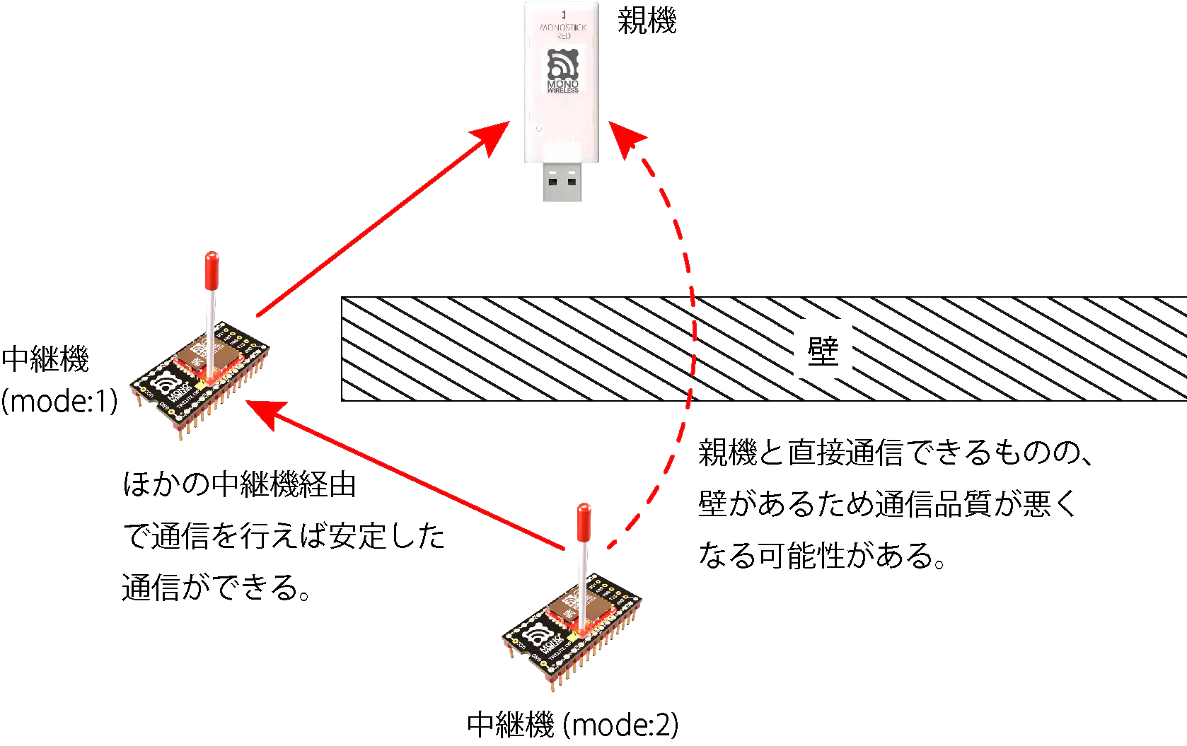
When Performing Static Routing (Directly Specifying Relay Destination)

When relaying with Relay Net, considering the layout as shown in the figure below, Repeater 2 automatically selects either the Parent or Repeater 1 as the connection destination.

Basically, fewer relays tend to have a higher delivery rate to the Parent, but if the Parent is selected as the connection destination for Repeater 2, communication quality may deteriorate due to obstacles between Parent and Repeater 2, resulting in a lower delivery rate to the Parent than when relaying through Repeater 1.

Therefore, this app has a function (static routing function) to specify the connection destination of Repeaters by TWELITE serial number.

Relay Net

When performing static routing, set the route from Repeater 2 to Repeater 1 statically, or set all routes statically.

Setting all routes increases the amount of configuration and does not support redundancy for situations such as Repeater failure or changes in radio conditions, but it eliminates the time to determine the upper communication destination and allows prompt relay operation.

To perform static routing, set the connection destination as shown in the table below: Repeater 1’s connection destination is the Parent’s SID, and Repeater 2’s connection destination is Repeater 1’s SID.

Example: Two-stage relay (Parent ← Repeater 1 ← Repeater 2 ← Child)

TWELITE SID ExampleConnection Destination (A: Access Point Address) Setting ExampleOperating Mode (l:Mode) Setting Example
Parent810F155E-0
Repeater 1810E18E8810F155E (Parent’s SID)※1
Repeater 2810F17FF810E18E8 (Repeater 1’s SID)2

※ If you only want to deal with effects caused by walls as shown in the figure, this setting is unnecessary.

2 - Interactive Mode (Parent and Repeater App)

Detailed setting changes using Interactive Mode
You can perform detailed app settings in Interactive Mode.

This section explains features specific to the Parent and Repeater App (App_Wings). For common features, please refer to the TWELITE APPS Manual Top Page.

Display Example

The screen shown below will be displayed.

[CONFIG MENU/App_Wings:0/v1-02-1/SID=820163B2]
a: (0x67720102) Application ID [HEX:32bit]
c: (18        ) Channels Set
x: (      0x03) RF Power/Retry [HEX:8bit]
b: (38400,8N1 ) UART Baud [9600-230400]
o: (0x00000000) Option Bits [HEX:32bit]
k: (0xA5A5A5A5) Encryption Key [HEX:32bit]
m: (         0) Mode (Parent or Router)
A: (0x00000000) Access point address [HEX:32bit]

 [ESC]:Back [!]:Reset System [M]:Extr Menu

Commands

ItemDefaultNotes
aApplication ID0x6772010232bit
cFrequency Channel1811-26
xRetry Count and Transmission Power03
Retry Count01-9 times, 0 means default 0 times
Transmission Power30-3
bUART Alternative Settings38400,8N1Enabled by option bit
oOption Bits0x00000000Other detailed settings
kEncryption Key0xA5A5A5A532bit
mOperating Mode0Parent 0, Repeater 1, Repeater Network 1-63
ARepeater Destination0x00000000Repeater mode only

Details of each command are shown below.

a: Application ID

All devices communicating must have the same value. It logically separates networks.

c: Frequency Channel

All devices communicating must have the same value. It physically separates networks.

x: Transmission Power and Retry Count

Specify the radio transmission power and the number of additional packet retransmissions.

b: UART Alternative Settings

Specify UART options when the option bit Enable UART Alternative Settings is set.

The value specifies baud rate and parity settings separated by a comma.

The baud rate can be selected from 9600/19200/38400/57600/115200/230400. Specifying other values may cause errors.

Parity can be set as N: None, O: Odd, E: Even. Hardware flow control cannot be set. Settings like 8N1, 7E2 can be specified, but settings other than 8N1 are unverified. Please confirm operation in advance.

o: Option Bits

Specify a 32bit numeric value. Settings linked to each bit can be enabled.

Bit MaskSettingDefault
0x00000200Enable UART Alternative Settings0️⃣
0x00000400Stop Periodic Packet Transmission Output0️⃣
0x00001000Enable Encrypted Communication0️⃣
0x00002000Enable Plain Reception During Encrypted Communication0️⃣

k: Encryption Key

Specify a 32bit hexadecimal encryption key when the option bit Enable Encrypted Communication is set.

m: Operating Mode

Set 0 for Parent mode, 1 for Repeater mode.

When performing multi-hop repeater in Repeater mode, setting 2-63 specifies the repeater layer.

A: Repeater Destination

Specify the serial ID (0x8???????) of the upper-level device connected when performing static routing in Repeater mode. When set to 0x00000000, automatic search is performed.

Details of Option Bits

Explanation of settings linked to each bit of the option bit value.

00000200: Enable UART Alternative Settings

Enables b: UART Alternative Settings.

00000400: Stop Periodic Packet Transmission Output

Stops the 1-second periodic transmission of the Extremely Simple! Standard App and Remote Control App and stops UART output during continuous mode.

00001000: Enable Encrypted Communication

Enables encrypted communication. The other party must also enable encrypted communication.

00002000: Enable Plain Reception During Encrypted Communication

When encrypted communication is enabled, allows reception of packets that are not encrypted.