Here you will find important information that we recommend you read first.
This is the multi-page printable view of this section. Click here to print...
For suitable output, we recommend to use Google Chrome (15+) or Microsoft Edge (79+).
Getting Started
- 1: TWELITE DIP
- 1.1: Getting Started
- 1.2: Customization via Interactive Mode
- 1.3: PC Integration via UART
- 1.4: Transmitting Binary Data
- 1.5: Advanced Digital Transmission with Remote Control App
- 2: TWELITE STICK
- 2.1: Evaluation and Configuration with TWELITE STAGE APP
- 2.2: Communicating with Child Devices Using Python (Basic)
- 3: TWELITE SPOT
- 3.1: Getting Started
- 3.2: Basics of Firmware Development with ESP32
- 3.3: Receiving Data from a TWELITE Child
- 3.4: Related Information
- 4: TWELITE STAGE SDK / act
- 4.1: Development Environment
- 4.2: Installing the SDK
- 4.3: Building Act
- 4.4: Creating a New Project
- 4.5: Installing VSCode for act
- 4.6: Build Definition Makefile
- 4.7: Other Platforms
1 - TWELITE DIP
Transmit digital and analog signals using the Extremely Simple! Standard App
The Extremely Simple! Wireless Module TWELITE DIP is a product with TWELITE mounted on a 2.54mm pitch board. It is suitable for prototyping and small-scale production because it can be easily wired by hand.
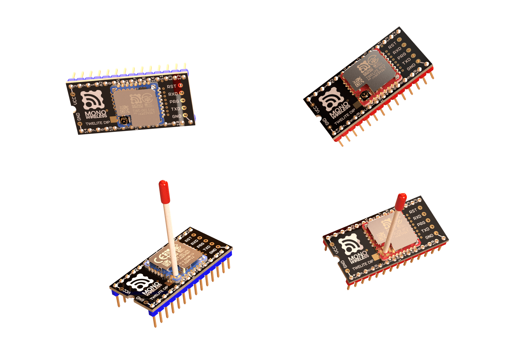
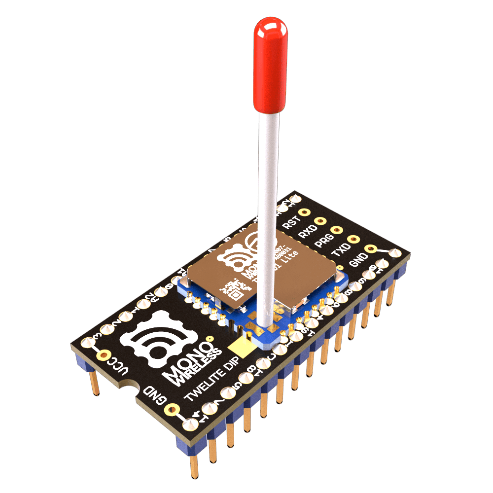
Appearance
For product specifications, see the Data Sheet.
Ready-to-Use Wireless Module
Extremely Simple! Standard App
TWELITE DIP comes with the Extremely Simple! Standard App (App_Twelite) installed at the time of shipment.
The Extremely Simple! Standard App is firmware that transmits digital and analog signals.
| Digital | Analog | UART | I2C |
|---|---|---|---|
| One side’s digital input reflected to the other’s digital output | One side’s analog input reflected to the other’s PWM output | One side’s serial input reflected to the other’s serial output | Access the target of the child device from the parent device |
Basic digital and analog signal transmission can be achieved “extremely easily” just by wiring.
Simple Wireless Communication
TWELITE can communicate immediately after startup. Pairing like Bluetooth is not required.
Broadcast communication is performed between devices set to the same frequency channel. Therefore, multiple devices cannot transmit simultaneously on the same channel. Packets not addressed to the device are ignored. You can think of it as working like a transceiver or intercom.
TWELITE can transmit without receiving, enabling the realization of devices with excellent power-saving performance.
What is the wireless communication standard?
TWELITE is a wireless module that uses 2.4GHz radio waves and complies with IEEE 802.15.4, which is a different standard from Bluetooth (IEEE 802.15.1). Other products conforming to IEEE 802.15.4 include Zigbee modules, but TWELITE is not a Zigbee module. Zigbee modules use the Zigbee protocol stack on top of IEEE 802.15.4, whereas TWELITE implements a simple, proprietary protocol stack instead.
Although it is not suitable for large-volume data communication, it is optimal for simple signal transmission and similar applications.
Small amounts of data can be transmitted efficiently.
Pin Functions
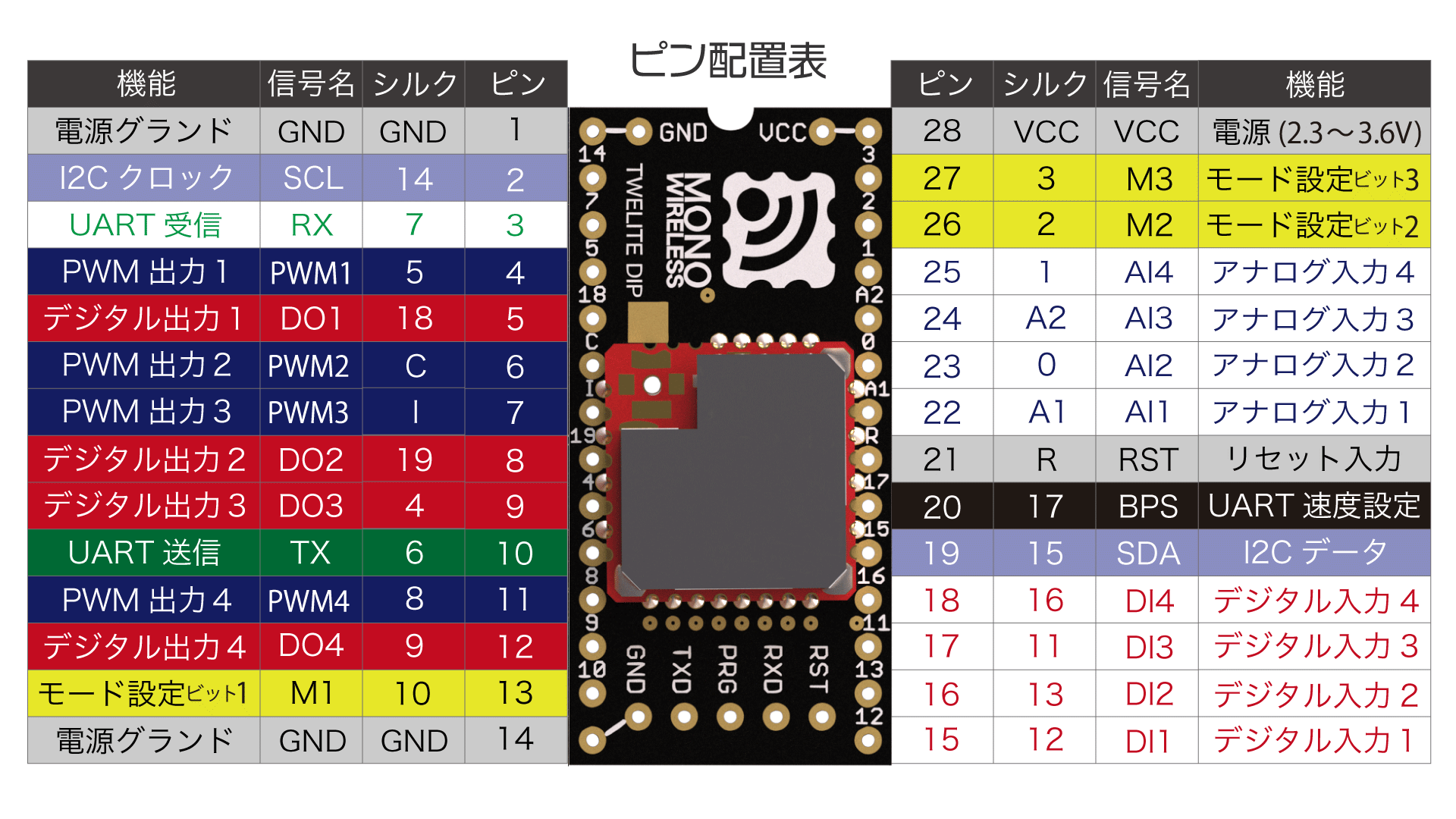
Pin Layout Table
The pins used by the Extremely Simple! Standard App have several functions.
- Power input (3.3V)
VCC/GND2.3-3.6V
- Digital/analog input/output
DIxreflected toDOxAIxreflected toPWMx
- Serial communication
TX/RXUARTSCL/SDAI2C
- Configuration input
Mxto switch operating modeBPSto select alternative baud rate
RSTReset input
x: Any number
For details about each pin function, see the Extremely Simple! Standard App Manual.
1.1 - Getting Started
Transmit digital and analog signals using the Extremely Simple! Standard App
Extremely Simple! The Extremely Simple! Standard App (App_Twelite) allows you to achieve basic signal transmission just by wiring.
Using the Extremely Simple! Standard App pre-installed on the factory-default TWELITE DIP, let’s try reflecting the signal input to one
DIx/AIx port onto the other DOx/PWMx port.Products Used
 |
|---|
| TWELITE DIP |
| TWELITE Parent / Child / Repeater |
| Extremely Simple! Standard App |
| 2 units (3 units when using a Repeater) |
TWELITE DIP can be either the BLUE series or the RED series.
One-Way Signal Transmission
Signals input to the Parent can be output from the Child.
The Parent sends data to all Children
When multiple Children are prepared, the Parent’s
DIx can simultaneously control the DOx of all Children.Digital Signal
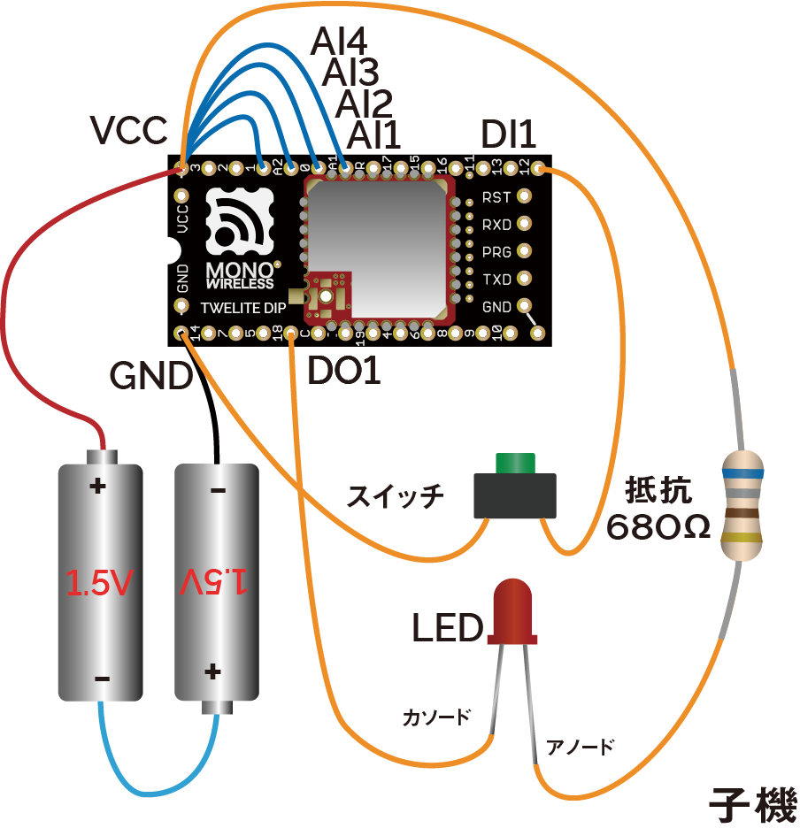
Pressing the switch connected to the Parent lights the LED connected to the Child, and releasing the switch on the Parent turns off the LED on the Child.
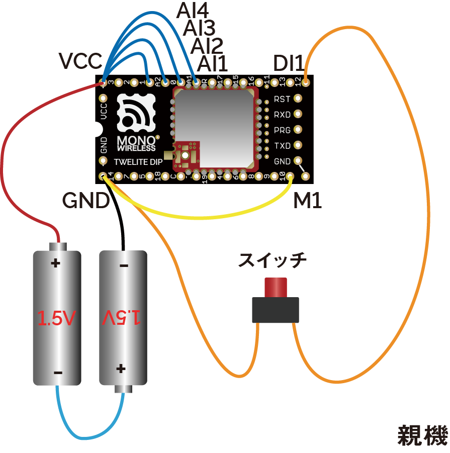
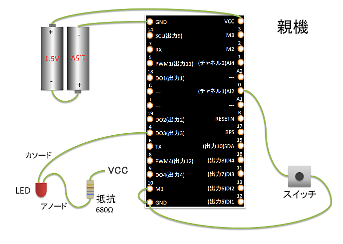
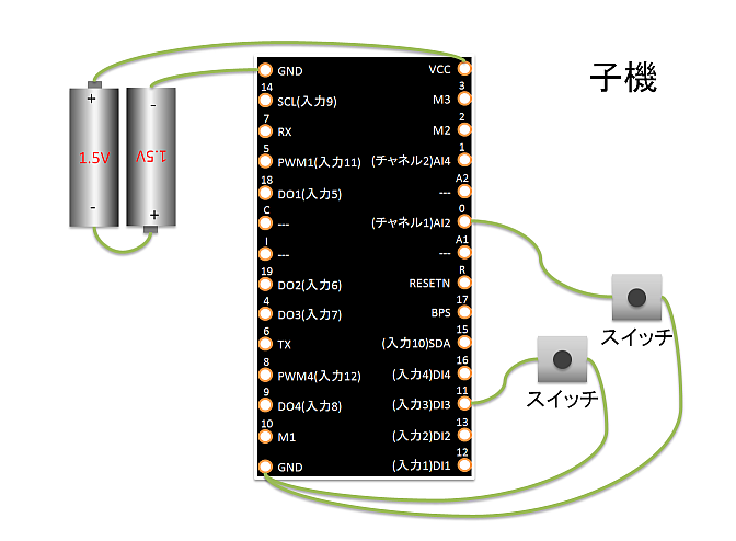
Parent Wiring
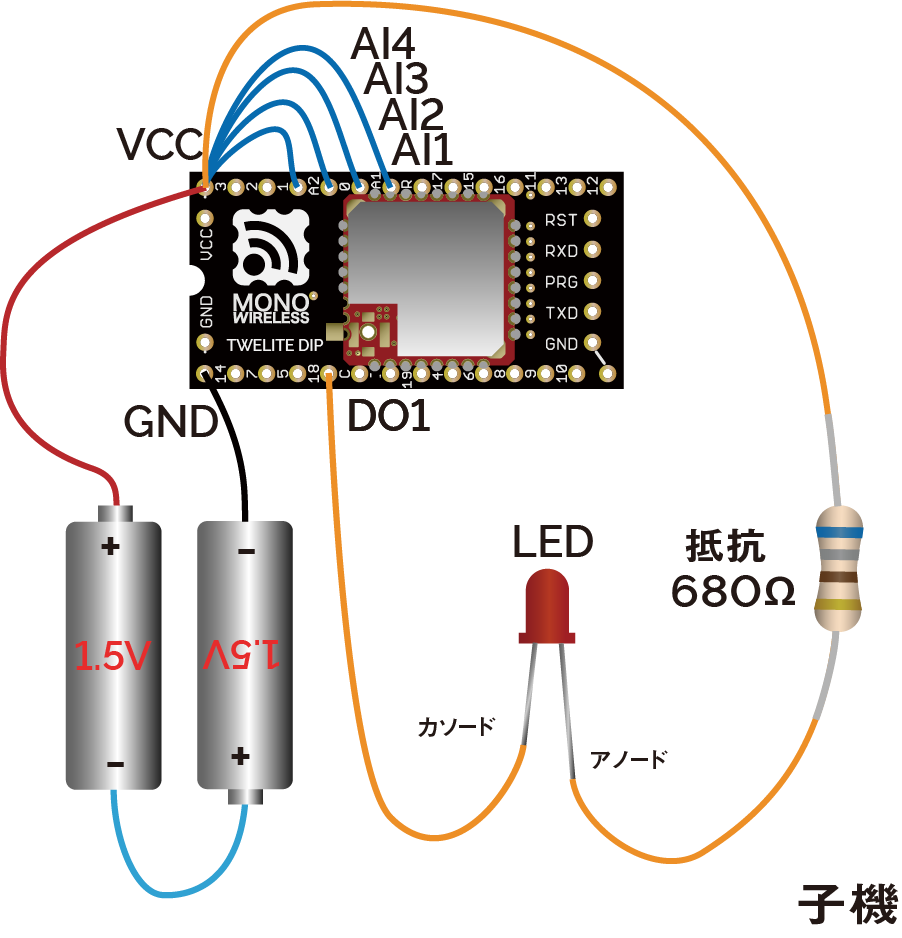
Child Wiring
In the above example, only DI1 and DO1 are used, but there are a total of 4 ports. Other ports can be used similarly.
Connect the M1 pin of one TWELITE DIP to GND. This unit will act as the Parent.
Also, connect unused AIx ports to VCC to disable them (this can be omitted by changing settings in Interactive Mode).
Please connect a current-limiting resistor to the LED.
Output current capacity is limited
| Supply Voltage | Drive Capacity |
|---|---|
| 2.7V-3.6V | 4mA |
| 2.2V-2.7V | 3mA |
| 2.0V-2.2V | 2.5mA |
If exceeding the drive capacity, please use a MOSFET or transistor.
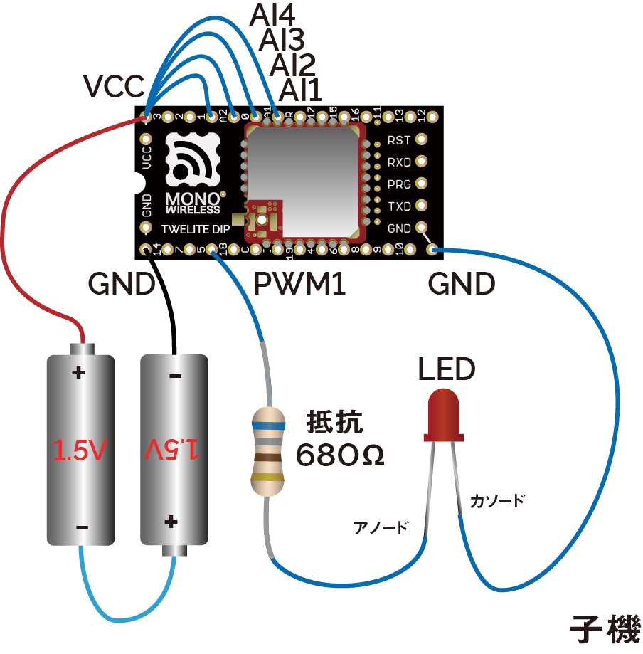
Analog Signal
Turning the potentiometer connected to the Parent changes the brightness of the LED connected to the Child.
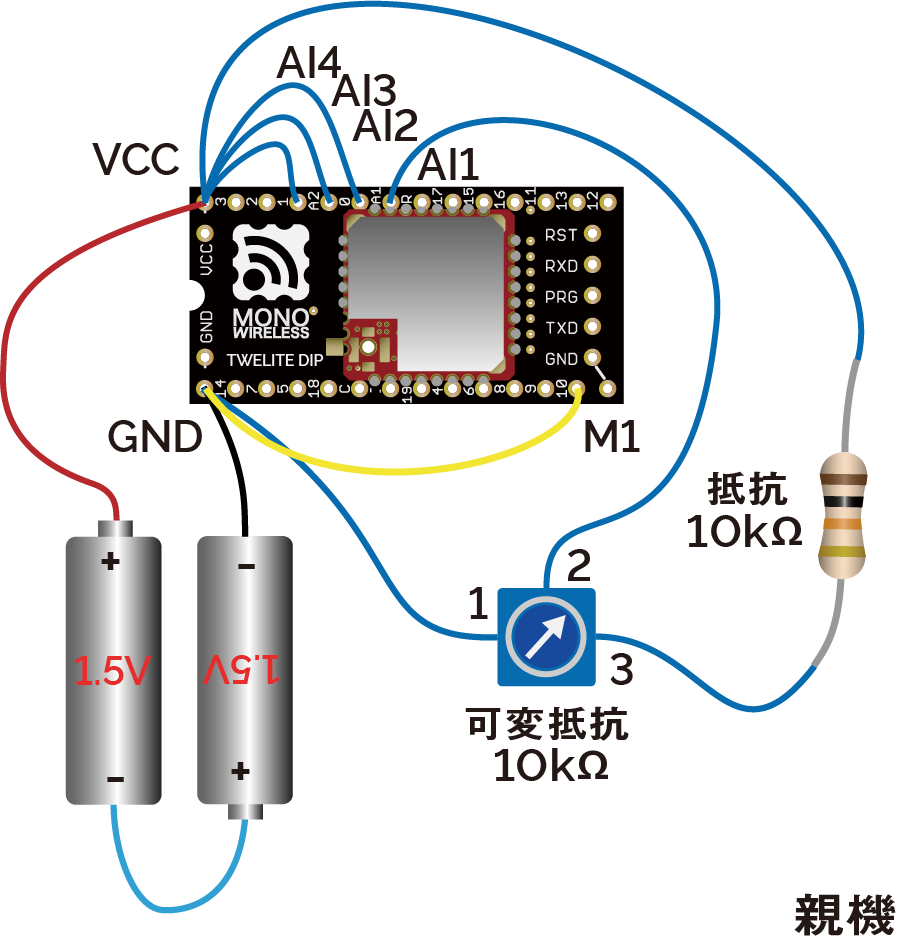
Parent Wiring
Child Wiring
In the above example, only AI1 and PWM1 are used, but there are a total of 4 ports. Other ports can be used similarly.
About input/output voltage
The analog input operates at 2.0V or below.
In the above example, the supply voltage is divided in half by a potentiometer (10KΩ) and a resistor (10KΩ). In the initial state of the Extremely Simple! Standard App, the output adjusted for the potentiometer is applied to PWMx. When the duty cycle is \(duty\), the input voltage \(V_{input}\), and the supply voltage \(V_{cc}\), the calculation formula is as follows:
\(duty=min(230\frac{V_{input}}{V_{cc}}-5, 100)\)
If you set the option bit 0x00000040 using Interactive Mode, full scale output is possible for inputs below 1.8V (inputs above 2.0V are treated as unused).
\(duty=100\frac{min(V_{input}, 1.8)}{1.8}\)
If anything is wired to PWM2 or PWM3, firmware writing may fail.
These pins have functions used during firmware writing (Details).
Two-Way Signal Transmission
Signal transmission can be performed not only from Parent to Child but also from Child to Parent in the same way.
The Parent receives data from all Children
When multiple Children are prepared, the exclusive DIx of each Child can control the Parent’s DOx in parallel.
(Example: Reflect one Child’s DI1 to the Parent’s DO1, and another Child’s DI2 to the Parent’s DO2)
Let’s extend the digital signal transmission example to two-way. The analog signal transmission example can be extended similarly.
Pressing the switch connected to the Parent lights the LED connected to the Child, and releasing the switch on the Parent turns off the LED on the Child. At the same time, pressing the switch connected to the Child lights the LED connected to the Parent, and releasing the switch on the Child turns off the LED on the Parent.
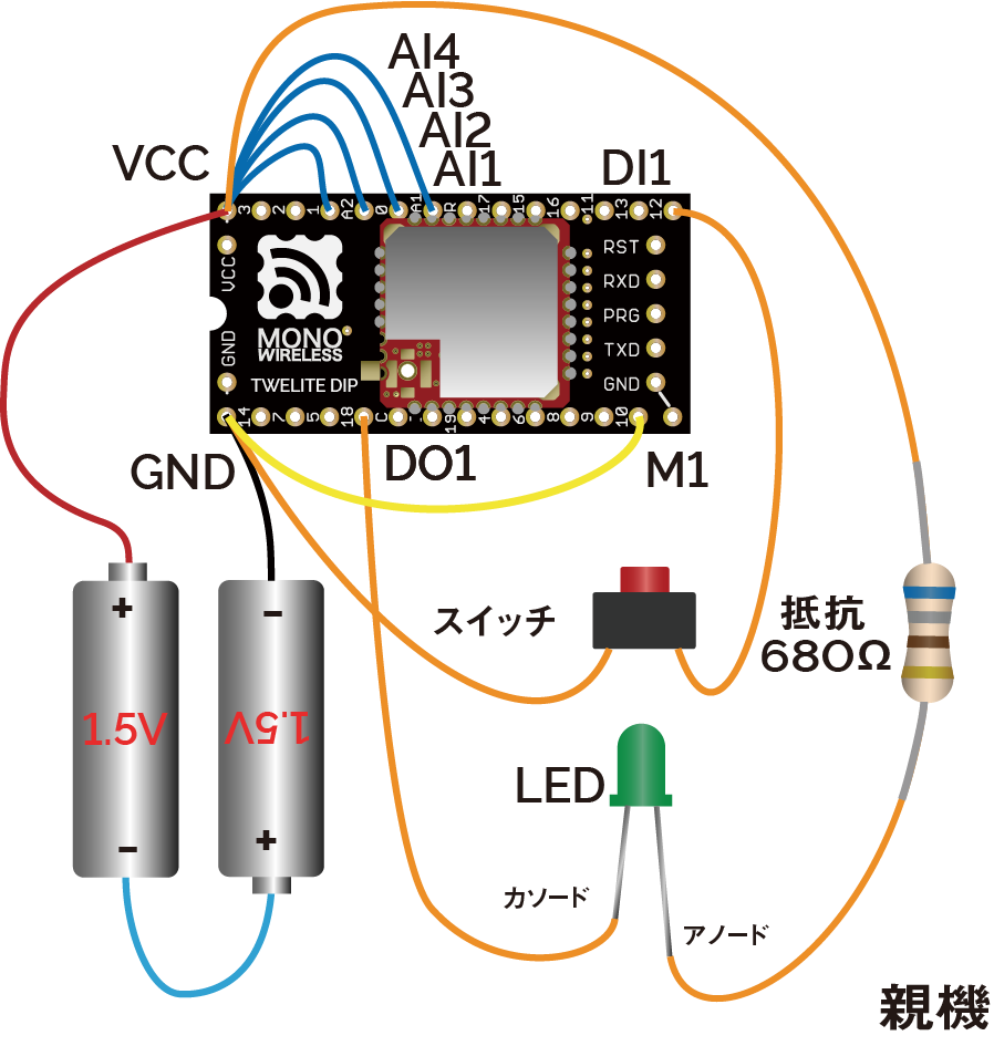
Parent Wiring
Child Wiring
In the above example, only DI1 and DO1 are used, but there are a total of 4 ports. Other ports can be used similarly.
Installing a Repeater
By placing a unit configured as a Repeater between the Parent and Child, communication distance can be extended. Up to 3 stages of repeaters can be used.
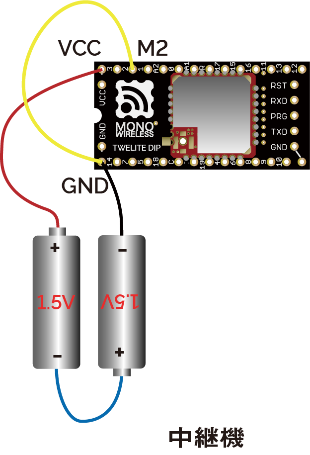
Repeater Wiring
Connect M2 to GND.
1.2 - Customization via Interactive Mode
Customize functionality using Interactive Mode
By using Interactive Mode, you can change various parameters such as network grouping and enabling low latency mode.
What is Interactive Mode
Interactive Mode is a mode used when connecting the TWELITE series to a PC for configuration. By connecting the TWELITE series to a PC via a USB adapter TWELITE R series, you can change various parameters through UART communication.
We recommend using the TWELITE STAGE app. The TWELITE STAGE app is a tool that includes functions for firmware configuration and writing, as well as features to evaluate communication with the parent device. The TWELITE STAGE app is included in the TWELITE STAGE SDK.
For more details about the TWELITE STAGE app, please refer to the TWELITE APPS Manual.
For details on each parameter in the Extremely Simple! Standard App, please see the Extremely Simple! Standard App Manual.
Custom Examples
Below are customization examples of TWELITE DIP for different purposes.
Please select and try the ones you are interested in.
- Network Grouping
- Prepare two pairs of parent and child devices and operate them independently
- Using Low Latency Mode
- Prepare a pair of parent and child devices and reduce delay in transmission from
DIxtoDOx
- Prepare a pair of parent and child devices and reduce delay in transmission from
- Transmit Only When Button is Pressed
- Prepare a pair of parent and child devices and configure so that transmission occurs only when the parent’s button is pressed
Network Grouping
By default, all TWELITE DIP devices can communicate with each other. When you prepare two pairs of parent and child devices, the inputs of the parent are reflected to both children, and the inputs of the children are reflected to both parents.
Using Interactive Mode, change the Application ID and frequency channel to separate the two pairs so they can be used independently at the same time.
Products Used
|  |
|---|---|
| TWELITE DIP | TWELITE R2 |
| TWELITE Parent / Child | USB Adapter |
| Extremely Simple! Standard App | - |
| 4 units | 1 unit |
Customization Details
Set the Interactive Mode values as follows to divide the two pairs into Group A and Group B.
- Group A
- Parent / Child
- Application ID:
0xAAAAAAAA - Frequency Channel:
11
- Application ID:
- Parent / Child
- Group B
- Parent / Child
- Application ID:
0xBBBBBBBB - Frequency Channel:
26
- Application ID:
- Parent / Child
The Application ID logically separates the network, and the frequency channel physically separates it. If the number of groups is 16 or less, it is recommended to change both.
It is recommended to space frequency channels as much as possible.
Customization Procedure
- Insert the TWELITE DIP into the TWELITE R2 and connect it to the PC using a USB-C cable
- Launch the TWELITE STAGE app and select the target TWELITE R2 from Serial Port Selection
- From the Main Menu, select “3: Interactive Mode”
- Press uppercase
Rto reset settings to default - Press
a, inputAAAAAAAA/BBBBBBBB, and pressEnter - Press
c, input11/26, and pressEnter - Press uppercase
Sto apply settings (TWELITE will reset) - Press
ESCseveral times to return to the Main Menu and disconnect the TWELITE R2 USB-C cable - Remove the TWELITE DIP and insert it into a breadboard or connect it to the circuit
Operation Check
Wire both Group A and Group B as in the “Try It Out First” One-Way Digital Signal Example, connecting a switch to the parent and an LED to the child.
- Pressing the switch on Group A’s parent lights only Group A’s child LED
- Pressing the switch on Group B’s parent lights only Group B’s child LED
Change the Application ID of Group B’s child to 0xAAAAAAAA and the frequency channel to 11.
- Pressing the switch on Group A’s parent lights LEDs on both children
Using Low Latency Mode
By default, there is a delay of about 30-70ms from when the source DIx changes until it is reflected on the destination DOx. This delay exists due to processing to avoid chattering and wireless packet interference.
Low Latency Mode shortens this delay to about 3-10ms by simplifying these processes.
Enable low latency mode on the transmitting device (parent) via Interactive Mode.
Low latency mode is useful in cases such as:
- When the hardware has no concern about chattering
- When input states change rapidly
Products Used
| |
|---|---|
| TWELITE DIP | TWELITE R2 |
| TWELITE Parent / Child | USB Adapter |
| Extremely Simple! Standard App | - |
| 2 units | 1 unit |
Customization Details
Set the Interactive Mode values as follows to enable low latency mode on the transmitting device (parent).
- Parent
- Child: No change
The option bits value is a 32-bit unsigned integer. You can enable corresponding settings by setting flags on each bit.
To enable multiple settings simultaneously, take the logical OR of all.
Customization Procedure
- Insert the TWELITE DIP into the TWELITE R2 and connect it to the PC using a USB-C cable
- Launch the TWELITE STAGE app and select the target TWELITE R2 from Serial Port Selection
- From the Main Menu, select “3: Interactive Mode”
- Press uppercase
Rto reset settings to default - Press
o, input00000001, and pressEnter - Press uppercase
Sto apply settings (TWELITE will reset) - Press
ESCseveral times to return to the Main Menu and disconnect the TWELITE R2 USB-C cable - Remove the TWELITE DIP and insert it into a breadboard or connect it to the circuit
Operation Check
Wire the parent and child as in the “Try It Out First” One-Way Digital Signal Example, connecting a switch to the parent and an LED to the child.
- Pressing the parent’s switch lights the child’s LED
- The operation is the same as the default state, but you might notice slightly improved response
- Connect an oscilloscope to the parent’s
DO1and child’sDI1to compare and confirm the effect
Transmit Only When Button is Pressed
By default, transmission occurs when the input state changes and also once every second.
In this case, for example, if the transmitting device’s button is held down and the power is cut, the output on the receiving side remains.
The Transmit Only When Button is Pressed setting causes the transmitting device to repeatedly send when DIx is Low, and continue sending for one second after transitioning to High. If the receiving device’s DOx is set Low and reception stops, it returns to High.
Change the setting via Interactive Mode to transmit only when the button is pressed.
This is useful for applications such as rotating a motor while a remote control button is pressed.
Since transmission continues at short intervals while
DIx is Low, increasing the number of transmitters on the same frequency channel is not recommended. Apply this option only for 1:1 communication.Products Used
| |
|---|---|
| TWELITE DIP | TWELITE R2 |
| TWELITE Parent / Child | USB Adapter |
| Extremely Simple! Standard App | - |
| 2 units | 1 unit |
Customization Details
Set the Interactive Mode values as follows to change the behavior of digital input/output on the transmitting device (parent) and receiving device (child).
- Parent / Child
- Option Bits:
0x00000100
- Option Bits:
Customization Procedure
- Insert the TWELITE DIP into the TWELITE R2 and connect it to the PC using a USB-C cable
- Launch the TWELITE STAGE app and select the target TWELITE R2 from Serial Port Selection
- From the Main Menu, select “3: Interactive Mode”
- Press uppercase
Rto reset settings to default - Press
o, input00000100, and pressEnter - Press uppercase
Sto apply settings (TWELITE will reset) - Press
ESCseveral times to return to the Main Menu and disconnect the TWELITE R2 USB-C cable - Remove the TWELITE DIP and insert it into a breadboard or connect it to the circuit
Operation Check
Wire the parent and child as in the “Try It Out First” One-Way Digital Signal Example, connecting a switch to the parent and an LED to the child.
- Pressing the parent’s switch lights the child’s LED
- If the parent’s switch is held down and the power supply is cut off, the child’s LED turns off (it does not turn off in the default state)
1.3 - PC Integration via UART
Connect the Parent to a PC and send/receive data via UART
By using UART communication, you can integrate the Parent with a PC.
Use the TWELITE STAGE app and Python scripts to communicate over UART, allowing you to acquire and control Child device data from your PC via the Parent.
Products Used
| |
|---|---|
| TWELITE DIP | TWELITE R2 |
| TWELITE Parent/Child | USB Adapter |
| Extremely Simple! Standard App | - |
| 2 units | 1 unit |
Note: The TWELITE DIP and TWELITE R2 pair is functionally equivalent to a single MONOSTICK. You may also use the following combination:
|  |
|---|---|
| TWELITE DIP | MONOSTICK |
| TWELITE Child | TWELITE Parent |
| Extremely Simple! Standard App | Parent/Repeater App |
| 1 unit | 1 unit |
Installing the TWELITE STAGE App
The TWELITE STAGE app is a tool that offers features for configuring and writing firmware, as well as evaluating communication with the Parent.
Here, let’s use the TWELITE STAGE app to display and control data from a TWELITE DIP Child (Extremely Simple! Standard App).
The TWELITE STAGE app is included in the TWELITE STAGE SDK.
For installation instructions, please see the TWELITE STAGE SDK Manual.
Receiving Data with the TWELITE STAGE App
The data sent from the Child running the Extremely Simple! Standard App includes information such as the input state of the DIx/AIx ports, power supply voltage, and the logical device ID of the sender.
Displaying Serial Strings
Data received by the Parent from the Child can be obtained by interpreting the strings output by the Parent over serial (UART). Let’s display this string first.
The default serial communication settings are 115200bps 8-N-1.
Start the TWELITE STAGE app and select the Parent in Serial Port Selection. Then open Main Menu > 1: Viewer > 1: Terminal.
When data is received from the Child, a message like the following will be displayed:
:78811501C98201015A000391000C2E00810301FFFFFFFFFB
By interpreting such strings output by the Parent, you can obtain the data sent by the Child.
The above string represents the following data
| # | Data | Description | Value | |
|---|---|---|---|---|
: | char | Header | : | |
78 | 0 | uint8 | Sender Logical Device ID | 0x78 |
81 | 1 | uint8 | Command Number | 0x81 |
15 | 2 | uint8 | Packet Identifier | 0x15 |
01 | 3 | uint8 | Protocol Version | 0x01 |
C9 | 4 | uint8 | LQI | 201/255 |
8201015A | 5 | uint32 | Sender Serial ID | 0x201015A |
00 | 9 | uint8 | Destination Logical ID | 0x00 |
0391 | 10 | uint16 | Timestamp | approx. 14.27 seconds |
00 | 12 | uint8 | Number of Relays | 0 |
0C2E | 13 | uint16 | Power Supply Voltage | 3118mV |
00 | 15 | int8 | - | |
81 | 16 | uint8 | Digital Signal | DI1 L DI2 HDI3 H DI4 H(Periodic Tx) |
03 | 17 | uint8 | Digital Signal Mask | DI1 DI2 |
01 | 18 | uint8 | AI1 Converted Value | 16mV |
FF | 19 | uint8 | AI2 Converted Value | Not used |
FF | 20 | uint8 | AI3 Converted Value | Not used |
FF | 21 | uint8 | AI4 Converted Value | Not used |
FF | 22 | uint8 | AIx Correction Value | AI1 0x03 |
FB | uint8 | Checksum | 0xFB | |
char | Footer | \r | ||
char | Footer | \n |
The strings output by the TWELITE Parent follow the format below:
| Header | Payload | Checksum | Footer |
|---|---|---|---|
: | repeated 00-FF | LRC8 of payload | CRLF |
- All ASCII characters*
- Starts with
:(0x3A) - Ends with CRLF (
\r\n/0x0D 0x0A) - Big-endian
*Except for binary format in serial communication apps
Standard App Viewer
The above format is machine-friendly, but to check the content as a human, you need to interpret it. The TWELITE STAGE app provides a function to interpret and display strings representing data sent from Children running the Extremely Simple! Standard App. The Python library described below also performs this interpretation.
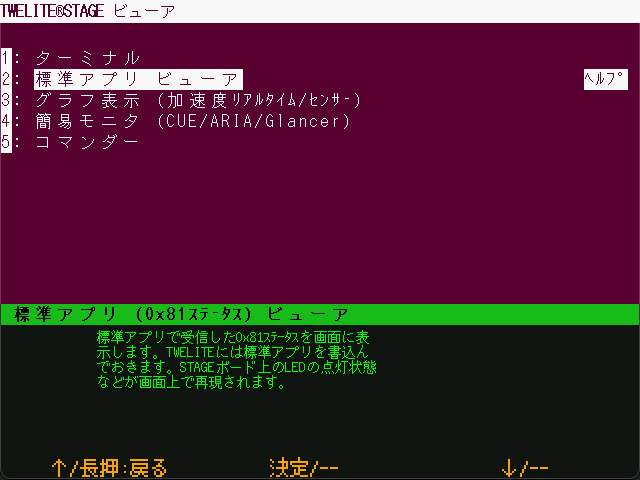
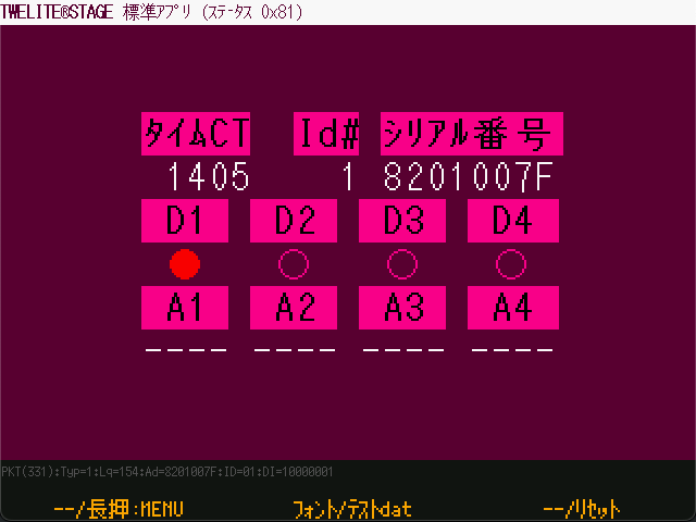
Return to Main Menu > 1: Viewer, and open 2: Standard App Viewer.
You can check the timestamp, logical device ID, serial ID, and the values of DIx/AIx.
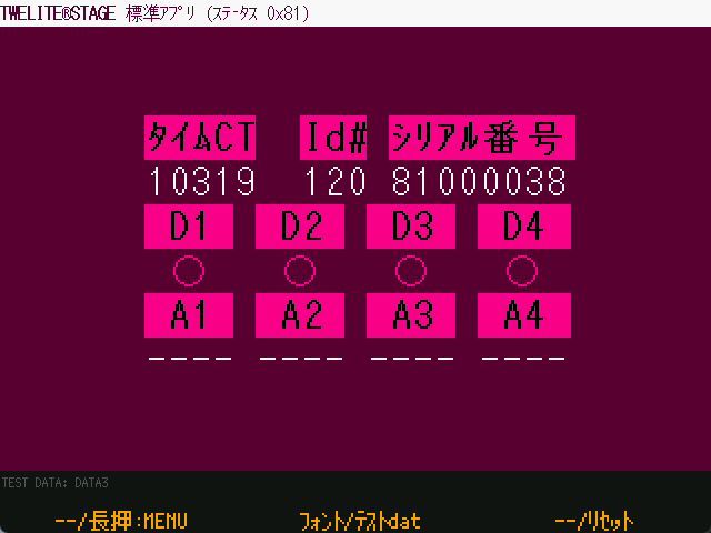
Standard App Viewer screen
Sending Data with the TWELITE STAGE App
Conversely, you can send wireless packets from the Parent to the Child to change the output state of the Child.
Commander
Return to Main Menu > 1: Viewer, and open 5: Commander.
You can send packets simulating DIx and AIx inputs.
For detailed instructions, see the TWELITE STAGE APP Manual.
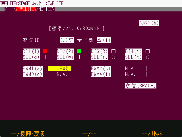
Commander screen
How to use:
- Select the destination and input state
- Click Send
Commander sends strings from the PC to the Parent over serial communication. In other words, it works in the opposite direction to the Standard App Viewer.
This string also starts with : and ends with CRLF. For the detailed format, see the Extremely Simple! Standard App Manual.
Python Scripts
Both the “Standard App Viewer” and “Commander” in the TWELITE STAGE app simply exchange strings over serial communication. If you have an environment that supports serial communication, you can integrate your own application with the Parent.
Here, let’s use a Python script to display the input state of
DI1, and then control the output of DO1.By leveraging Python scripts, you can process and save received data, or control output ports from your own software.
This section assumes the reader has knowledge and experience with Python.
Installing the MWings Library
The MWings library makes it easy to integrate TWELITE and Python scripts. Specifically, it interprets strings representing data received from the Child and constructs data to be sent to the Child.
It can be installed from PyPI.
For details about the library, see the MWings for Python Manual and the MWings for Python API Reference.
The following assumes an environment using pyenv and poetry, but MWings works on Python 3.12 and later. Feel free to use your preferred environment.
Receiving Data with a Python Script
Let’s implement a Python script that displays a message when a button connected to DI1 on the TWELITE DIP is pressed.
Running the Sample Script
Create a script named dip_show_di1.py with the following content:
# -*- coding:utf-8 -*-
# TWELTIE DIP start guide: receiving in python

import mwings as mw


def main():
    twelite = mw.Twelite(mw.utils.ask_user_for_port())

    @twelite.on(mw.common.PacketType.APP_TWELITE)
    def on_app_twelite(packet):
        if packet.di_state[0]:
            print("DI1 Pressed")

    try:
        twelite.daemon = True
        twelite.start()
        print("Started receiving")
        while True:
            twelite.join(0.5)
    except KeyboardInterrupt:
        print("Flushing...")
        twelite.stop()
        print("Completed")


if __name__ == "__main__":
    main()
When you run the script, it will output DI1 Pressed when the Child’s DI1 goes Low.
If multiple TWELITE R series or MONOSTICK series devices are connected at runtime, select the serial port attached to the Parent.
poetry run python dip_show_di1.py
Multiple ports detected.
[1] /dev/cu.usbserial-R2xxxxxx TWE-Lite-R (Genuine)
[2] /dev/cu.usbserial-R2xxxxxx TWE-Lite-R (Genuine)
Select [1-2]: 2
Selected: /dev/cu.usbserial-R2xxxxxx
Started receiving
DI1 Pressed
DI1 Pressed
^CFlushing...
Completed
The above is an example for macOS. On Windows, COM port names are displayed.
Press Ctrl-C to exit.
Explanation of the Sample Script
Importing the MWings Library
import mwings as mw
The library is imported as the shorthand mw, similar to pandas as pd or numpy as np.
Creating the Object
twelite = mw.Twelite(mw.utils.ask_user_for_port())
This creates a Twelite object, which serves as the interface for communicating with the Parent.
You specify the serial port as an argument, but here we use the mw.utils.ask_user_for_port() utility to select it dynamically. This function outputs an error message if no serial port exists, returns the port if only one is found, or prompts the user if multiple are present.
Registering a Receive Event Handler
    @twelite.on(mw.common.PacketType.APP_TWELITE)
    def on_app_twelite(packet):
        if packet.di_state[0]:
            print("DI1 Pressed")
This registers an event handler that is called when a packet is received from a Child running the Extremely Simple! Standard App.
Event handler registration uses a Python decorator (?). Here, since we are targeting data from the Extremely Simple! Standard App (App_Twelite), we use @twelite.on(mw.common.PacketType.APP_TWELITE). The function defined immediately after this decorator becomes the handler. The function name can be anything, but it must be defined after initializing the Twelite object.
To detect when the Child’s DI1 becomes Low, the receive handler checks the first boolean value in the List-like object di_state (digital interface state) of the packet variable (mwings.parsers.app_twelite.ParsedPacket). Each value in di_state is True when Low.
Handling Other Data
The packet variable contains not only input states but also information about the sender and receiver. For example, by using to_json(), you can output all data in JSON format as follows:
    @twelite.on(mw.common.PacketType.APP_TWELITE)
    def on_app_twelite(packet):
        print(packet.to_json(verbose=True, spread=False))
Here, verbose enables inclusion of system information, and spread expands List-like objects.
If you have pandas installed, you can also obtain a DataFrame using to_df():
    @twelite.on(mw.common.PacketType.APP_TWELITE)
    def on_app_twelite(packet):
        print(packet.to_df(verbose=False).to_string())
Waiting for Data
        twelite.daemon = True
        twelite.start()
        print("Started receiving")
        while True:
            twelite.join(0.5)
Here, the script waits for data from the Parent in a separate thread.
The Twelite object is a subclass of threading.Thread, and this mechanism launches a daemon thread, blocking the main thread until the script ends.
Why use a while loop and join(0.5)?
This is to allow the main thread to receive signals, so the script can exit cleanly when Ctrl-C is pressed.
Cleanup
        print("Flushing...")
        twelite.stop()
        print("Completed")
When Ctrl-C is pressed, twelite.stop() is called to terminate the subthread.
Sending Data with a Python Script
Next, let’s implement a Python script to blink an LED connected to DO1 on the TWELITE DIP from the PC.
Running the Sample Script
Create a script named dip_blink_led.py with the following content:
# -*- coding:utf-8 -*-
# TWELITE DIP start guide: blinking from python

from time import sleep

import mwings as mw


def main():
    twelite = mw.Twelite(mw.utils.ask_user_for_port())

    initial = {
        "destination_logical_id": 0x78,
        "di_to_change": [True, False, False, False],
        "di_state": [False, False, False, False],
    }
    command = mw.serializers.app_twelite.Command(**initial)

    while True:
        command.di_state[0] = not command.di_state[0]
        twelite.send(command)
        print(f"Flip DO1: {command.di_state[0]}")
        sleep(1)


if __name__ == "__main__":
    try:
        main()
    except KeyboardInterrupt:
        print("...Aborting")
When you run the script, the Child’s DO1 will blink every second.
If multiple TWELITE R series or MONOSTICK series devices are connected at runtime, select the serial port attached to the Parent.
poetry run python dip_blink_led.py
Multiple ports detected.
[1] /dev/cu.usbserial-R2xxxxxx TWE-Lite-R (Genuine)
[2] /dev/cu.usbserial-R2xxxxxx TWE-Lite-R (Genuine)
Select [1-2]: 2
Selected: /dev/cu.usbserial-R2xxxxxx
Flip DO1: True
Flip DO1: False
Flip DO1: True
Flip DO1: False
Flip DO1: True
^C...Aborting
Explanation of the Sample Script
Importing the MWings Library
import mwings as mw
The library is imported as the shorthand mw, similar to pandas as pd or numpy as np.
Creating the Object
twelite = mw.Twelite(mw.utils.ask_user_for_port())
This creates a Twelite object, which serves as the interface for communicating with the Parent.
You specify the serial port as an argument, but here we use the mw.utils.ask_user_for_port() utility to select it dynamically. This function outputs an error message if no serial port exists, returns the port if only one is found, or prompts the user if multiple are present.
Creating the Command to Send to the Parent
    initial = {
        "destination_logical_id": 0x78,
        "di_to_change": [True, False, False, False],
        "di_state": [False, False, False, False],
    }
    command = mw.serializers.app_twelite.Command(**initial)
This initializes a command object (mwings.serializers.app_twelite.Command), which represents the packet to be sent to a Child running the Extremely Simple! Standard App.
The dictionary initial represents the initial state of the command. Here, the destination logical device ID is set to 0x78 (all Children), with DI1 as the target for change, and initially set to High.
Sending the Data
    while True:
        command.di_state[0] = not command.di_state[0]
        twelite.send(command)
        print(f"Flip DO1: {command.di_state[0]}")
        sleep(1)
Here, the command data is converted to a string and sent to the Parent every second.
Blinking is achieved by toggling the first boolean value in the List-like object di_state (digital interface state) of the command data, which controls the state of DOx.
1.4 - Transmitting Binary Data
Transmit arbitrary bytes via UART communication
By using the Serial Communication App, you can send and receive arbitrary binary data.
Let’s use TWELITE as a device to wireless-enable serial communication and try sending byte data between PCs.
There is also a product specialized for binary data transmission: TWELITE UART.
If you are using TWELITE UART, you can skip Writing Firmware and start from List of Communication Modes onward.
Products Used
| |
|---|---|
| TWELITE DIP | TWELITE R2 |
| TWELITE Parent/Child | USB Adapter |
| Serial Communication App | - |
| 2 units | 2 units |
Note: The TWELITE DIP and TWELITE R2 pair is equivalent to a single MONOSTICK. The following combination is also acceptable.
|
|---|
| MONOSTICK |
| TWELITE Parent/Child |
| Serial Communication App |
| 2 units |
Serial Communication App
Rewrite the TWELITE firmware to the Serial Communication App (App_Uart), which is specialized for wireless serial communication. While the “Extremely Simple! Standard App” also has a function for transmitting binary data via serial communication, its functionality is very limited.
Writing Firmware
Rewrite all Parent, Child, and Repeater devices.
- Install the TWELITE STAGE SDK and launch the TWELITE STAGE App
- From Serial Port Selection, select the connected device
- From the “Main Menu”, select “2: App Write”
- Choose “1: Select from BIN” and select
App_Uart... - Press
Enterseveral times until the write is complete
By default, after a successful write, the device transitions to the following Interactive Mode screen.
--- CONFIG/TWE UART APP V1-04-5/SID=0x82018ca0/LID=0x78 -- ---
 a: set Application ID (0x67720103)
 i: set Device ID (120=0x78)
 c: set Channels (18)
 x: set RF Conf (3)
 r: set Role (0x0)
 l: set Layer (0x1)
 b: set UART baud (38400)
 B: set UART option (8N1)
 m: set UART mode (E)
 k: set Tx Trigger (sep=0x0d0a, min_bytes=0 dly=0[ms])
 h: set header format [;U;%t;%i;0x%A;%q;%s;<*>;%X;\n]
 C: set crypt mode (0)
 o: set option bits (0x00000100)
---
 S: save Configuration
 R: reset to Defaults
List of Communication Modes
The Serial Communication App provides five communication modes, allowing you to select the most suitable one for your application.
- Format Mode (ASCII): Applies a format to both transmission and reception.
- Format Mode (Binary): The binary version of Format Mode (ASCII).
- Chat Mode: Mode for text chat.
- Transparent Mode: Purely wireless-enables UART without applying any format.
- Header Transparent Mode: Applies a format only to the receiver’s output.
By default, the app starts in Header Transparent Mode.
For details on each communication mode of the Serial Communication App, please refer to the manual.
Below, we introduce communication test procedures using four of these modes. Please select and try the mode that interests you.
- Header Transparent Mode
- No format is applied on the transmitting side.
- The receiver’s output format provides information such as the logical device ID of the sender and the received radio signal quality.
- This is a well-balanced mode.
- Transparent Mode
- No format is applied to either transmission or reception.
- The input on the transmitting side and the output on the receiving side are equivalent.
- This is the simplest mode, but functionality is limited.
- Format Mode (ASCII)
- Applies a format to both transmission and reception.
- Requires external devices to support the format, but allows you to specify the destination and identify the sender.
- Binary data is represented as hexadecimal strings.
- Format Mode (Binary)
- Applies a format to both transmission and reception.
- Requires external devices to support the format, but allows you to specify the destination and identify the sender.
- Binary data is represented as-is.
In this example, we will connect two TWELITEs to the same PC and loop back data. Normally, you would use this to connect external devices wirelessly.
Header Transparent Mode
Let’s use Header Transparent Mode to send the ASCII string Hello from both sides.
How to Configure
The default mode of the Serial Communication App is Header Transparent Mode. Therefore, you can use it as-is with the initial settings.
Communication Test
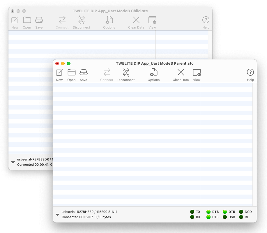
1. Launch Two TWELITE STAGE Apps
Start two instances of the TWELITE STAGE App (TWELITE_Stage.exe/.command/.run).
It’s not mandatory, but we recommend duplicating the executable file (for example:
TWELITE_Stage_1 and TWELITE_Stage_2).2. Open the Terminal
After selecting the serial port on both TWELITE STAGE Apps, choose “1: Viewer” > “1: Terminal”.
3. Send from One Side
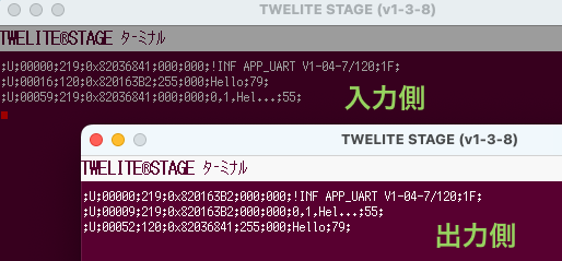
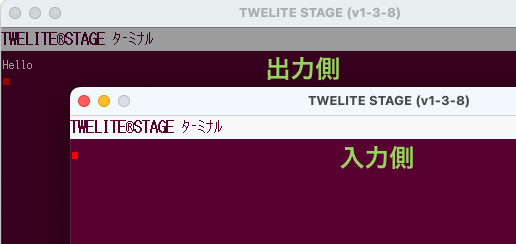
Select one of the windows, type Hello, and press Enter. The message will appear in the other window.
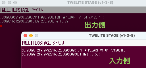
Send from One Side
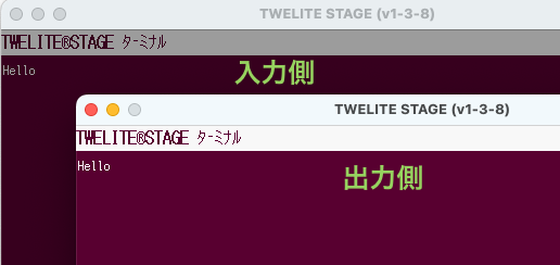
4. Send from the Other Side
Select the other window, type Hello, and press Enter. The message will appear in the original window.
Send from the Other Side
The following sequence can be interpreted as shown below.
;U;00052;120;0x82036841;255;000;Hello;79;
| Data | Description | Value | |
|---|---|---|---|
U | char | Fixed value | U |
00052 | uint16 | Timestamp at output | 52 seconds |
120 | uint8 | Sender’s logical device ID | 120 (Child without ID) |
0x82036841 | uint32 | Sender’s extended address | 82036841 |
255 | uint8 | LQI (Link Quality Indicator) | 255/255 |
000 | uint8 | Sender’s sequence number | 0 |
Hello | [uint8] | Input data | Hello |
79 | uint8 | XOR checksum | 0x79 |
For details on the format, please refer to the manual.
Transparent Mode
Let’s try sending the ASCII string Hello from both sides using Transparent Mode.
How to Configure
Set m: Communication Mode to D.
For an overview and instructions on Interactive Mode, please refer to the TWELITE APPS Manual.
Communication Test
1. Launch Two TWELITE STAGE Apps
Start two instances of the TWELITE STAGE App (TWELITE_Stage.exe/.command/.run).
This is not mandatory, but we recommend duplicating the executable file (e.g.,
TWELITE_Stage_1 and TWELITE_Stage_2).2. Open the Terminal
In both TWELITE STAGE Apps, after selecting the serial port, choose “1: Viewer” > “1: Terminal”.
3. Send from One Side
Select one of the windows, type Hello, and press Enter. The message will appear in the other window.
Send from One Side
Because there is no echo-back function, the characters you type will not be displayed on the input side’s terminal.
4. Send from the Other Side
Select the other window, type Hello, and press Enter. The message will appear in the original window.
Send from the Other Side
Since no formatting is applied to either input or output, the data you enter is output as-is.
Hello
Format Mode (ASCII)
Let’s use Format Mode (ASCII) to send the binary data 0x5A 0xAB 0x90 0x00 from both sides.

Saab 9000 CD 2.3
How to Configure
Set m: Communication Mode to A.
Set i: Logical Device ID to 0 (Parent) on one device, and to 1 (Child, ID 1) on the other.
For an overview and usage instructions for Interactive Mode, please refer to the TWELITE APPS Manual.
Communication Test (Simple Format)
Let’s first try the simple, basic format.
1. Launch Two TWELITE STAGE Apps
Start two instances of the TWELITE STAGE App (TWELITE_Stage.exe/.command/.run).
It’s not required, but we recommend duplicating the executable file (e.g.,
TWELITE_Stage_1 and TWELITE_Stage_2).2. Open the Terminal
After selecting the serial port in both TWELITE STAGE Apps, choose “1: Viewer” > “1: Terminal”.
3. Send from the Parent Side
First, copy the following sequence:
:01235AAB900047
The above sequence represents the following:
| Data | Description | Value | |
|---|---|---|---|
: | char | Header (fixed value) | : |
01 | uint8 | Destination logical device ID | 0x01 Child |
23 | uint8 | Arbitrary command number | 0x23 |
5AAB9000 | [uint8] | Data to send | 0x5A 0xAB 0x90 0x00 |
47 | uint8 | Checksum (LRC) | 0x47 |
char | Footer (newline) | CR (0x0D/\r) | |
char | Footer (newline) | LF (0x0A/\n) |
For details of the format, see the manual.
Next, select the Parent side window.
Finally, paste with Alt+V/⌘+V and press Enter. The data will be reflected on the Child side window.
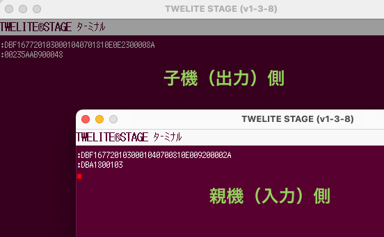
Send from Parent Side
There is no echo-back function, and manual input will time out. Please use copy & paste.
On the receiving side, the sequence can be interpreted as follows:
:00235AAB900048
| Data | Description | Value | |
|---|---|---|---|
: | char | Header (fixed value) | : |
00 | uint8 | Sender’s logical device ID | 0x00 Parent |
23 | uint8 | Command number | 0x23 |
5AAB9000 | [uint8] | Received data | 0x5A 0xAB 0x90 0x00 |
48 | uint8 | Checksum (LRC) | 0x48 |
char | Footer (newline) | CR (0x0D/\r) | |
char | Footer (newline) | LF (0x0A/\n) |
For details of the format, see the manual.
For the format of the sender’s response message
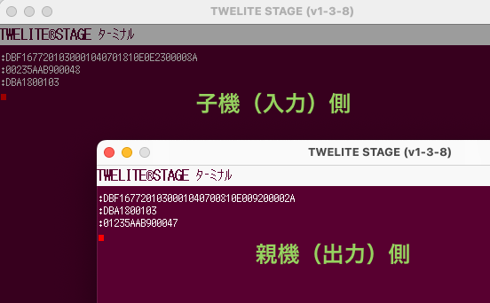
:DBA1..., see the manual.4. Send from the Child Side
First, copy the following sequence:
:00235AAB900048
The above sequence represents the following:
| Data | Description | Value | |
|---|---|---|---|
: | char | Header (fixed value) | : |
00 | uint8 | Destination logical device ID | 0x00 Parent |
23 | uint8 | Arbitrary command number | 0x23 |
5AAB9000 | [uint8] | Data to send | 0x5A 0xAB 0x90 0x00 |
48 | uint8 | Checksum (LRC) | 0x48 |
char | Footer (newline) | CR (0x0D/\r) | |
char | Footer (newline) | LF (0x0A/\n) |
For details of the format, see the manual.
Next, select the Child side window.
Finally, paste with Alt+V/⌘+V and press Enter. The data will be reflected on the Parent side window.
Send from Child Side
On the receiving side, the sequence can be interpreted as follows:
:01235AAB900047
| Data | Description | Value | |
|---|---|---|---|
: | char | Header (fixed value) | : |
01 | uint8 | Sender’s logical device ID | 0x01 Child |
23 | uint8 | Command number | 0x23 |
5AAB9000 | [uint8] | Received data | 0x5A 0xAB 0x90 0x00 |
47 | uint8 | Checksum (LRC) | 0x47 |
char | Footer (newline) | CR (0x0D/\r) | |
char | Footer (newline) | LF (0x0A/\n) |
For details of the format, see the manual.
For the format of the sender’s response message
:DBA1..., see the manual.Communication Test (Extended Format)
Next, let’s try the advanced extended format.
1. Launch Two TWELITE STAGE Apps
Start two instances of the TWELITE STAGE App (TWELITE_Stage.exe/.command/.run).
This is not required, but we recommend duplicating the executable file (e.g.,
TWELITE_Stage_1 and TWELITE_Stage_2).2. Open the Terminal
After selecting the serial port in both TWELITE STAGE Apps, choose “1: Viewer” > “1: Terminal”.
3. Send from the Parent Side
First, copy the following sequence:
:01A0CDFF5AAB9000FE
The above sequence represents the following:
| Data | Description | Value | |
|---|---|---|---|
: | char | Header (fixed value) | : |
01 | uint8 | Destination logical device ID | 0x01 Child |
A0 | uint8 | Command number (fixed value) | 0xA0 |
CD | uint8 | Arbitrary response ID | 0xCD |
FF | uint8 | Option None | 0xFF |
5AAB9000 | [uint8] | Data to send | 0x5A 0xAB 0x90 0x00 |
FE | uint8 | Checksum (LRC) | 0xFE |
char | Footer (newline) | CR (0x0D/\r) | |
char | Footer (newline) | LF (0x0A/\n) |
For details of the format, see the manual.
Next, select the Parent side window.
Finally, paste using Alt+V/⌘+V and press Enter. The data will appear in the Child side window.
Send from Parent Side
There is no echo-back function, and manual input will time out. Please use copy & paste.
On the receiving side, the sequence can be interpreted as follows:
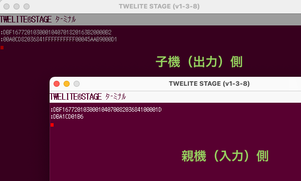
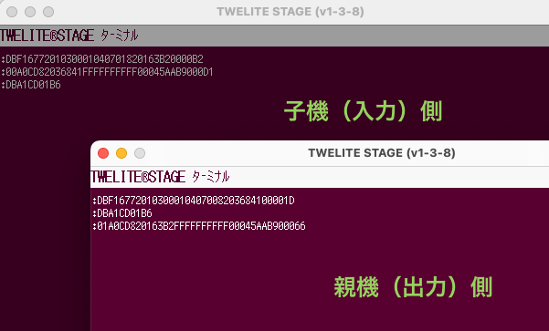
:00A0CD82036841FFFFFFFFFF00045AAB9000D1
| Data | Description | Value | |
|---|---|---|---|
: | char | Header (fixed value) | : |
00 | uint8 | Sender’s logical device ID | 0x00 Parent |
A0 | uint8 | Command number (fixed value) | 0xA0 |
CD | uint8 | Response ID | 0xCD |
82036841 | uint32 | Sender’s extended address | 0x82036841 |
FFFFFFFF | uint32 | Destination extended address | 0xFFFFFFFF None |
FF | uint8 | LQI | 255/255 |
0004 | uint16 | Length of following data | 4 bytes |
5AAB9000 | [uint8] | Received data | 0x5A 0xAB 0x90 0x00 |
D1 | uint8 | Checksum (LRC) | 0xD1 |
char | Footer (newline) | CR (0x0D/\r) | |
char | Footer (newline) | LF (0x0A/\n) |
For details of the format, see the manual.
For the format of the sender’s response message
:DBA1..., see the manual.4. Send from the Child Side
First, copy the following sequence:
:00A0CDFF5AAB9000FF
The above sequence represents the following:
| Data | Description | Value | |
|---|---|---|---|
: | char | Header (fixed value) | : |
00 | uint8 | Destination logical device ID | 0x00 Parent |
A0 | uint8 | Command number (fixed value) | 0xA0 |
CD | uint8 | Arbitrary response ID | 0xCD |
FF | uint8 | Option None | 0xFF |
5AAB9000 | [uint8] | Data to send | 0x5A 0xAB 0x90 0x00 |
FF | uint8 | Checksum (LRC) | 0xFF |
char | Footer (newline) | CR (0x0D/\r) | |
char | Footer (newline) | LF (0x0A/\n) |
For details of the format, see the manual.
Next, select the Child side window.
Finally, paste using Alt+V/⌘+V and press Enter. The data will appear in the Parent side window.
Send from Child Side
On the receiving side, the sequence can be interpreted as follows:
:01A0CD820163B2FFFFFFFFFF00045AAB900066
| Data | Description | Value | |
|---|---|---|---|
: | char | Header (fixed value) | : |
01 | uint8 | Sender’s logical device ID | 0x01 Child |
A0 | uint8 | Command number (fixed value) | 0xA0 |
CD | uint8 | Response ID | 0xCD |
820163B2 | uint32 | Sender’s extended address | 0x820163B2 |
FFFFFFFF | uint32 | Destination extended address | 0xFFFFFFFF None |
FF | uint8 | LQI | 255/255 |
0004 | uint16 | Length of following data | 4 bytes |
5AAB9000 | [uint8] | Received data | 0x5A 0xAB 0x90 0x00 |
66 | uint8 | Checksum (LRC) | 0x66 |
char | Footer (newline) | CR (0x0D/\r) | |
char | Footer (newline) | LF (0x0A/\n) |
For details of the format, see the manual.
For the format of the sender’s response message
:DBA1..., see the manual.Format Mode (Binary)
Let’s use Format Mode (Binary) to send the binary data 0x5A 0xAB 0x90 0x00 from both sides.
Saab 9000 CD 2.3
From here on, the 0x prefix for binary data will be omitted.
For example, 0x5A 0xAB 0x90 0x00 will be shown as 5A AB 90 00.
How to Configure
Set m: Communication Mode to B.
Set the i: Logical Device ID to 0 (Parent) on one terminal, and to 1 (Child, ID 1) on the other.
For an overview and usage instructions for Interactive Mode, please refer to the TWELITE APPS Manual.
Prepare an Environment that Supports Binary Data
The terminal features of the TWELITE STAGE App and TeraTerm do not support binary data. You need to use a terminal software that supports binary format.
Here, we use CoolTerm as an example.
For how to install and configure CoolTerm, see the page UART Communication Without Using the STAGE App.
Communication Test (Simple Format)
Let’s first try the simple, basic format.
1. Open Two CoolTerm Windows
Open two CoolTerm windows and connect each to a device.
About Configuration
Set Options > Terminal > Terminal Mode to Raw Mode, and uncheck Options > Transmit > Send String Options > Terminate 'Send String' Data.
For details on configuration, see UART Communication Without Using the STAGE App.
To display received data in hexadecimal, select View > View Hex. Click Connect to connect.
Two CoolTerm windows open
2. Send from the Parent Side
Select the Parent window, then choose Connection > Send String... to open the send window, and select the Hex radio button.
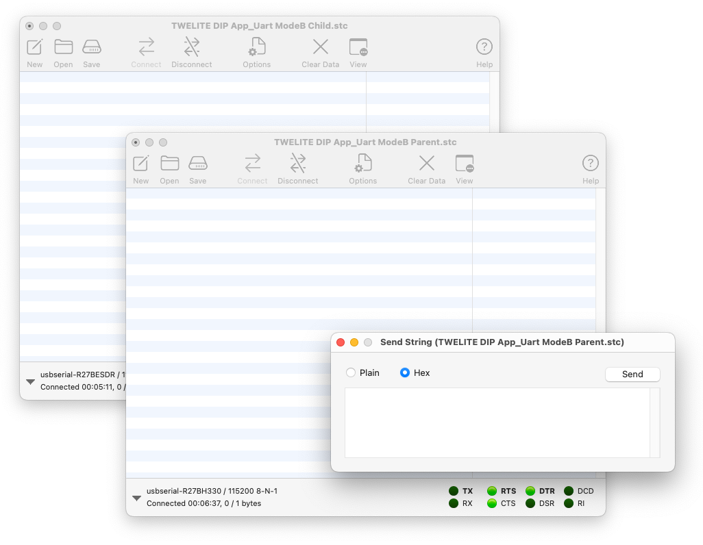
Send window open
Enter the following and click Send to transmit from the Parent.
A5 5A 80 06 01 23 5A AB 90 00 43 04
The above sequence represents the following:
| Data | Description | Value | |
|---|---|---|---|
A5 | uint8 | Header (fixed value) | 0xA5 |
5A | uint8 | Header (fixed value) | 0x5A |
8006 | uint16 | Data length | 6 bytes |
01 | uint8 | Destination Logical Device ID | 0x01 Child |
23 | uint8 | Arbitrary command number | 0x23 |
5AAB9000 | [uint8] | Data to send | 5A AB 90 00 |
43 | uint8 | Checksum (XOR) | 0x43 |
04 | uint8 | Footer | EOT (0x04) |
For details of the format, see the manual.
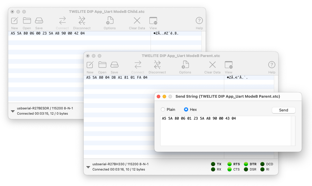
Send from Parent Side
On the receiving side, the sequence can be interpreted as follows:
A5 5A 80 06 00 23 5A AB 90 00 42 04
| Data | Description | Value | |
|---|---|---|---|
A5 | uint8 | Header (fixed value) | 0xA5 |
5A | uint8 | Header (fixed value) | 0x5A |
8006 | uint16 | Data length | 6 bytes |
00 | uint8 | Sender Logical Device ID | 0x00 Parent |
23 | uint8 | Command number | 0x23 |
5AAB9000 | [uint8] | Received data | 5A AB 90 00 |
42 | uint8 | Checksum (XOR) | 0x42 |
04 | uint8 | Footer | EOT (0x04) |
For details of the format, see the manual.
For the sender’s response message format
A5 5A 80 04 DBA1..., see the manual.3. Sending from the Child Side
Just as with the Parent, select the Child window, then go to Connection > Send String... to open the send window, and make sure the Hex radio button is selected.
Enter the following content and click Send to transmit to the Parent.
A5 5A 80 06 00 23 5A AB 90 00 42 04
The above sequence represents the following:
| Data | Description | Value | |
|---|---|---|---|
A5 | uint8 | Header (fixed value) | 0xA5 |
5A | uint8 | Header (fixed value) | 0x5A |
8006 | uint16 | Data length | 6 bytes |
00 | uint8 | Destination Logical Device ID | 0x00 Parent |
23 | uint8 | Arbitrary command number | 0x23 |
5AAB9000 | [uint8] | Data to send | 5A AB 90 00 |
42 | uint8 | Checksum (XOR) | 0x42 |
04 | uint8 | Footer | EOT (0x04) |
For details of the format, see the manual.
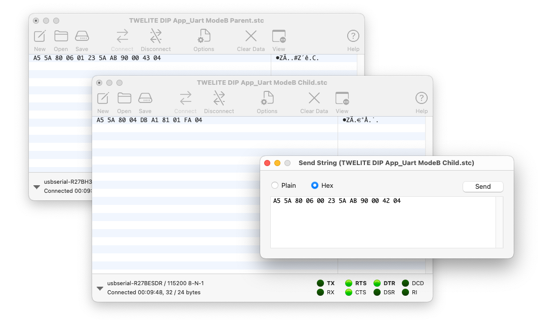
Send from Child Side
On the receiving side, the sequence can be interpreted as follows:
A5 5A 80 06 01 23 5A AB 90 00 43 04
| Data | Description | Value | |
|---|---|---|---|
A5 | uint8 | Header (fixed value) | 0xA5 |
5A | uint8 | Header (fixed value) | 0x5A |
8006 | uint16 | Data length | 6 bytes |
01 | uint8 | Sender Logical Device ID | 0x01 Child |
23 | uint8 | Command number | 0x23 |
5AAB9000 | [uint8] | Received data | 5A AB 90 00 |
43 | uint8 | Checksum (XOR) | 0x43 |
04 | uint8 | Footer | EOT (0x04) |
For details of the format, see the manual.
For the sender’s response message format
A5 5A 80 04 DB A1..., see the manual.Communication Test (Extended Format)
Next, let’s try the advanced extended format.
1. Open Two CoolTerm Windows
Open two CoolTerm windows and connect each to a device.
About Configuration
Set Options > Terminal > Terminal Mode to Raw Mode, and uncheck Options > Transmit > Send String Options > Terminate 'Send String' Data.
For details on configuration, see UART Communication Without Using the STAGE App.
To display received data in hexadecimal, select View > View Hex. Click Connect to connect.
Two CoolTerm windows open
2. Send from the Parent Side
Select the Parent window, then choose Connection > Send String... to open the send window, and select the Hex radio button.
Send window open
Enter the following and click Send to transmit to the Child.
A5 5A 80 08 01 A0 CD FF 5A AB 90 00 F2 04
The above sequence represents the following:
| Data | Description | Value | |
|---|---|---|---|
A5 | uint8 | Header (fixed value) | 0xA5 |
5A | uint8 | Header (fixed value) | 0x5A |
8008 | uint16 | Data length | 8 bytes |
01 | uint8 | Destination Logical Device ID | 0x01 Child |
A0 | uint8 | Command number (fixed value) | 0xA0 |
CD | uint8 | Arbitrary response ID | 0xCD |
FF | uint8 | Option None | 0xFF |
5AAB9000 | [uint8] | Data to send | 0x5A 0xAB 0x90 0x00 |
F2 | uint8 | Checksum (XOR) | 0xF2 |
04 | uint8 | Footer | EOT (0x04) |
For details of the format, see the manual.
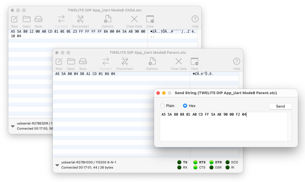
Send from Parent Side
On the receiving side, the sequence can be interpreted as follows:
A5 5A 80 12 00 A0 CD 81 0E 0E 23 FF FF FF FF BA 00 04 5A AB 90 00 10 04
| Data | Description | Value | |
|---|---|---|---|
A5 | uint8 | Header (fixed value) | 0xA5 |
5A | uint8 | Header (fixed value) | 0x5A |
8012 | uint16 | Data length | 18 bytes |
00 | uint8 | Sender Logical Device ID | 0x00 Parent |
A0 | uint8 | Command number (fixed value) | 0xA0 |
CD | uint8 | Response ID | 0xCD |
810E0E23 | uint32 | Sender extended address | 0x810E0E23 |
FFFFFFFF | uint32 | Destination extended address | 0xFFFFFFFF None |
BA | uint8 | LQI | 186/255 |
0004 | uint16 | Length of following data | 4 bytes |
5AAB9000 | [uint8] | Received data | 0x5A 0xAB 0x90 0x00 |
10 | uint8 | Checksum (XOR) | 0x10 |
04 | uint8 | Footer | EOT (0x04) |
For details of the format, see the manual.
For the sender’s response message format
A5 5A 80 04 DB A1..., see the manual.3. Send from the Child Side
As with the Parent, select the Child window, then go to Connection > Send String... to open the send window, and make sure the Hex radio button is selected.
Enter the following and click Send to transmit to the Parent.
A5 5A 80 08 00 A0 CD FF 5A AB 90 00 F3 04
The above sequence represents the following:
| Data | Description | Value | |
|---|---|---|---|
A5 | uint8 | Header (fixed value) | 0xA5 |
5A | uint8 | Header (fixed value) | 0x5A |
8008 | uint16 | Data length | 8 bytes |
00 | uint8 | Destination Logical Device ID | 0x00 Parent |
A0 | uint8 | Command number (fixed value) | 0xA0 |
CD | uint8 | Arbitrary response ID | 0xCD |
FF | uint8 | Option None | 0xFF |
5AAB9000 | [uint8] | Data to send | 0x5A 0xAB 0x90 0x00 |
F3 | uint8 | Checksum (XOR) | 0xF3 |
04 | uint8 | Footer | EOT (0x04) |
For details of the format, see the manual.
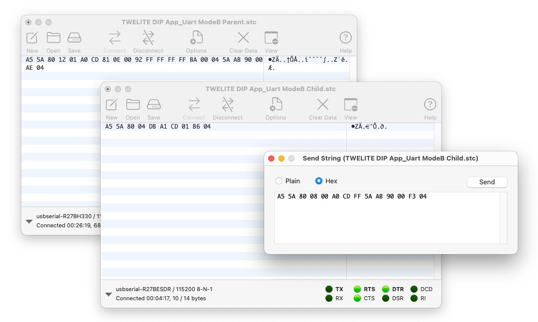
Send from Child Side
On the receiving side, the sequence can be interpreted as follows:
A5 5A 80 12 01 A0 CD 81 0E 00 92 FF FF FF FF BA 00 04 5A AB 90 00 AE 04
| Data | Description | Value | |
|---|---|---|---|
A5 | uint8 | Header (fixed value) | 0xA5 |
5A | uint8 | Header (fixed value) | 0x5A |
8012 | uint16 | Data length | 18 bytes |
01 | uint8 | Sender Logical Device ID | 0x01 Child |
A0 | uint8 | Command number (fixed value) | 0xA0 |
CD | uint8 | Response ID | 0xCD |
810E0092 | uint32 | Sender extended address | 0x820163B2 |
FFFFFFFF | uint32 | Destination extended address | 0xFFFFFFFF None |
BA | uint8 | LQI | 186/255 |
0004 | uint16 | Length of following data | 4 bytes |
5AAB9000 | [uint8] | Received data | 0x5A 0xAB 0x90 0x00 |
AE | uint8 | Checksum (XOR) | 0xAE |
04 | uint8 | Footer | EOT (0x04) |
For details of the format, see the manual.
For the sender’s response message format
A5 5A 80 04 DB A1..., see the manual.1.5 - Advanced Digital Transmission with Remote Control App
Use the Remote Control App to access advanced features specialized for digital signals
By writing the firmware from Extremely Simple! Standard App (App_Twelite) to the Remote Control App (App_IO), you can access advanced features specialized for digital signals.
Use the Remote Control App to utilize advanced features specialized for digital signal transmission. For example, you can increase the number of Child digital inputs to 12 channels.
Products Used
| |
|---|---|
| TWELITE DIP | TWELITE R2 |
| TWELITE Parent/Child | USB Adapter |
| Extremely Simple! Standard App | - |
| 2 units | 1 unit |
Remote Control App
Write the TWELITE firmware to the Remote Control App (App_IO), which is specialized for digital signal transmission. While the Extremely Simple! Standard App supports digital signal transmission, its I/O is limited to 4 lines. The Remote Control App expands the number of I/O and allows you to switch their combinations.
Writing the Firmware
Write the firmware to all Parent, Child, and other devices as follows:
- Install the TWELITE STAGE SDK and launch the TWELITE STAGE App
- Select the connected device from Serial Port Selection
- From the Main Menu, select 2: Firmware Write
- Select 1: Select from BIN and choose
App_IO... - Press
Enterseveral times until writing is complete
With the default settings, after a successful write, the device will switch to the following Interactive Mode screen:
--- CONFIG/APP_IO V1-03-2/SID=0x86300001/LID=0x00 ---
 a: set Application ID (0x67720107)
 i: set Device ID (--)
 c: set Channels (16)
 x: set Tx Power (3)
 t: set mode4 sleep dur (1000ms)
 y: set mode7 sleep dur (0s)
 f: set mode3 fps (16)
 d: set hold mask (000000000000)
 D: set hold dur (1000ms)
 o: set Option Bits (0x00000000)
 b: set UART baud (38400)
 p: set UART parity (N)
 C: set crypt mode (0)
 K: set crypt key []
---
 S: save Configuration
 R: reset to Defaults
Try It Out
By default, the Remote Control App is configured for one-way transmission, with the Child having 12 digital input ports and the Parent having 12 digital output ports. Let’s do the wiring.
| Name | Child | Parent | Standard | DIP # |
|---|---|---|---|---|
I1/O5 | I1 | O5 | DI1 | 15 |
I2/O6 | I2 | O6 | DI2 | 16 |
I3/O7 | I3 | O7 | DI3 | 17 |
I4/O8 | I4 | O8 | DI4 | 18 |
I5/O1 | I5 | O1 | DO1 | 5 |
I6/O2 | I6 | O2 | DO2 | 8 |
I7/O3 | I7 | O3 | DO3 | 9 |
I8/O4 | I8 | O4 | DO4 | 12 |
I9/O9 | I9 | O9 | SCL | 2 |
I10/O10 | I10 | O10 | SDA | 19 |
I11/O11 | I11 | O11 | PWM1 | 4 |
I12/O12 | I12 | O12 | PWM4 | 11 |
For details, see Remote Control App Pin Assignment.
Parent Wiring
In the default state, the Parent can receive up to 12 digital signals.
Parent wiring diagram
In the diagram above, DIP pin 9 (O3) is used as an output, but other Ox pins can be used similarly. To test the channel override function, which is not available in the Extremely Simple! Standard App, a tactile switch is connected to DIP pin 23 (C1).
Child Wiring
In the default state, the Child can send up to 12 digital signals.
Child wiring diagram
In the diagram above, DIP pin 17 (I3) is used as an input, but other Ix pins can be used similarly. Similarly, to test the channel override function, a tactile switch is connected to DIP pin 23 (C1).
Operation Check
- Press and release the button connected to the Child’s
I3.- The LED connected to the Parent’s
O3will turn on and off accordingly.
- The LED connected to the Parent’s
- While pressing the button connected to the Child’s
C1, press and release the button onI3.- Communication will not occur because the Child’s frequency channel is temporarily overridden.
- While pressing the buttons connected to both the Parent’s and Child’s
C1, press and release the button connected to the Child’sI3.- Communication will resume because both Parent and Child frequency channels are overridden to match.
The C1/C2 pins override the frequency channel as follows:
C2 | C1 | Frequency Channel |
|---|---|---|
| Not connected | Not connected | Default (initial value is 16) |
| Not connected | GND | 12 |
GND | Not connected | 21 |
GND | GND | 25 |
If you have extra buttons and LEDs, try increasing the number of I/O.
With 12 channels available, you could use, for example, a 7-segment LED.
Using Advanced Features
Let’s try changing settings in Interactive Mode for the following scenarios:
- Change the I/O assignment so both Child and Parent have 6 inputs and 6 outputs each
- Reflect the Child’s input to the Parent as quickly as possible
- Restore output signals if packets are lost
- Use the Child as a low-power remote
- Use the Child as a low-power remote supporting continuous transmission by long press
Assigning 6 Inputs and 6 Outputs to Both Child and Parent
By changing the value of Option Bits in Interactive Mode, you can select the I/O assignment from the following options:
| Child Input | Child Output | Parent Input | Parent Output | Note |
|---|---|---|---|---|
| 12 | 0 | 0 | 12 | Default |
| 8 | 4 | 4 | 8 | Option Bit 0x00001000 |
| 6 | 6 | 6 | 6 | Option Bit 0x00002000 |
| 0 | 12 | 12 | 0 | Option Bit 0x00003000 |
Let’s set both devices to have 6 inputs and 6 outputs.
- Launch the TWELITE STAGE App
- Select the connected device from Serial Port Selection
- From the Main Menu, select 3: Interactive Mode
- Press
Enterand confirm that the settings list is shown - Enter
o(lowercase), input the Option Bits value00002000, and pressEnter - Enter
S(uppercase) to save, then pressESCto exit
Now, the assignment with both Child and Parent having 6 inputs and 6 outputs will be as follows:
| Name | Child | Parent | Standard | DIP # |
|---|---|---|---|---|
I1/O5 | I1 | I1 | DI1 | 15 |
I2/O6 | I2 | I2 | DI2 | 16 |
I3/O7 | I3 | I3 | DI3 | 17 |
I4/O8 | I4 | I4 | DI4 | 18 |
I5/O1 | O1 | O1 | DO1 | 5 |
I6/O2 | O2 | O2 | DO2 | 8 |
I7/O3 | O3 | O3 | DO3 | 9 |
I8/O4 | O4 | O4 | DO4 | 12 |
I9/O9 | O5 | I5 | SCL | 2 |
I10/O10 | O6 | I6 | SDA | 19 |
I11/O11 | I5 | O5 | PWM1 | 4 |
I12/O12 | I6 | O6 | PWM4 | 11 |
Compared to the Extremely Simple! Standard App, you can handle two more digital signals!
Reflecting Child Input to Parent Output as Fast as Possible
When using the Child’s continuous mode, there is usually a delay of about 30-70ms from Child input to Parent output. If you need faster response, set Option Bits 0x00000001: Low Latency Mode via Interactive Mode.
Child Settings
- Launch the TWELITE STAGE App
- Select the connected device from Serial Port Selection
- From the Main Menu, select 3: Interactive Mode
- Press
Enterand confirm that the settings list is shown - Enter
o(lowercase), input the Option Bits value00000001, and pressEnter - Enter
S(uppercase) to save, then pressESCto exit
If multiple inputs change almost simultaneously, they are transmitted in order, which may cause delays for subsequent inputs.
Also, if input chattering occurs, it may be reflected directly to the output.
When Low Latency Mode is applied to the Child’s intermittent mode, its behavior differs from continuous mode:
- Upon wake-up by interrupt, only the value of the corresponding interrupt port is sent
- If a port is used as an interrupt wake-up pin, the states of other ports cannot be read simultaneously upon wake-up
- When returning from sleep, the IO port state is determined in 1/4 the usual time
Best suited for sending digital outputs from sensors, rather than buttons that may have chattering!
Restoring Output Signals When Packets Are Lost
If radio communication is interrupted while any input is held Low, the output will remain Low even if the actual input returns to High.
To return the signal to its original state when packets are lost, enable Remote Long Press Mode. In this mode, after the sending side input changes, the signal is sent continuously for a while. On the receiving side, if no packet indicating a Low state is received for a certain period, the output times out and returns to High.
Child Settings
- Set
M1/M2/M3open, and set Child: Continuous Mode - Launch the TWELITE STAGE App
- Select the connected device from Serial Port Selection
- From the Main Menu, select 3: Interactive Mode
- Press
Enterand confirm that the settings list is shown - Enter
o(lowercase), input the Option Bits value00000100and pressEnter - Enter
d(lowercase), input the hold/long-press target (for example,000000001010forI2andI4), and pressEnter - Enter
D(uppercase), input the hold/long-press time (the duration to continue sending after all inputs return from Low to High), and pressEnter - Enter
S(uppercase) to save, then pressESCto exit
Parent Settings
- Set
M1/M2/M3open, and set Child: Continuous Mode - Launch the TWELITE STAGE App
- Select the connected device from Serial Port Selection
- From the Main Menu, select 3: Interactive Mode
- Press
Enterand confirm that the settings list is shown - Enter
o(lowercase), input the Option Bits value00000100and pressEnter - Enter
d(lowercase), input the hold/long-press target (for example,000000001010forO2andO4), and pressEnter - Enter
D(uppercase), input the hold/long-press time (the duration to return the output from Low to High after signal loss), and pressEnter - Enter
S(uppercase) to save, then pressESCto exit
Ideal for applications such as remotely controlling motors from a remote control!
Using the Child as a Low Power Remote
If the Child is battery-powered, intermittent mode, which alternates sleep and wake, is effective. By combining Low Latency Mode and Hold Mode, the Parent’s output can be maintained for a set time when the Child’s button is pressed.
Child Settings
- Connect
M1/M2/M3toGNDand set Child: Intermittent 10s Mode - Launch the TWELITE STAGE App
- Select the connected device from Serial Port Selection
- From the Main Menu, select 3: Interactive Mode
- Press
Enterand confirm that the settings list is shown - Enter
o(lowercase), input the Option Bits value00000001and pressEnter - Enter
S(uppercase) to save, then pressESCto exit
Parent Settings
- Set
M1/M2/M3open, and set Child: Continuous Mode - Launch the TWELITE STAGE App
- Select the connected device from Serial Port Selection
- From the Main Menu, select 3: Interactive Mode
- Press
Enterand confirm that the settings list is shown - Enter
d(lowercase), input the hold/long-press target (for example,000000001010forO2andO4), and pressEnter - Enter
D(uppercase), input the hold/long-press time (hold time), and pressEnter - Enter
S(uppercase) to save, then pressESCto exit
Set the hold/long-press time according to your remote control requirements. For example, to keep a lamp on for a while when a button is pressed, use a longer time such as 3000 ms; for frequent button operations, a shorter time such as 50 ms is suitable.
Ideal for applications such as remotely controlling LEDs from a low-power remote!
Using the Child as a Low Power Remote with Long Press
If the Child is battery-powered, intermittent mode is effective. By combining Low Latency Mode and Remote Long Press Mode, the Child can continuously send data to the Parent while a button is held. Even after the button is released, the Child continues sending for a set period, and on the Parent side, if radio packets indicating the button remains pressed are lost for a set period, the output returns to its original state. This ensures reliable delivery of the Child’s input even in low-power operation.
Child Settings
- Connect
M1/M2/M3toGNDand set Child: Intermittent 10s Mode - Launch the TWELITE STAGE App
- Select the connected device from Serial Port Selection
- From the Main Menu, select 3: Interactive Mode
- Press
Enterand confirm that the settings list is shown - Enter
o(lowercase), input the Option Bits value00000103(00000100+00000001+00000002), and pressEnter - Enter
d(lowercase), input the hold/long-press target (for example,000000001010forI2andI4), and pressEnter - Enter
D(uppercase), input the hold/long-press time (the duration to continue sending after all inputs return from Low to High), and pressEnter - Enter
S(uppercase) to save, then pressESCto exit
Parent Settings
- Set
M1/M2/M3open, and set Child: Continuous Mode - Launch the TWELITE STAGE App
- Select the connected device from Serial Port Selection
- From the Main Menu, select 3: Interactive Mode
- Press
Enterand confirm that the settings list is shown - Enter
o(lowercase), input the Option Bits value00000100and pressEnter - Enter
d(lowercase), input the hold/long-press target (for example,000000001010forO2andO4), and pressEnter - Enter
D(uppercase), input the hold/long-press time (the duration to return the output from Low to High after signal loss), and pressEnter - Enter
S(uppercase) to save, then pressESCto exit
Ideal for applications such as remotely controlling motors from a low-power remote!
2 - TWELITE STICK
Connect TWELITE to your PC with a USB dongle
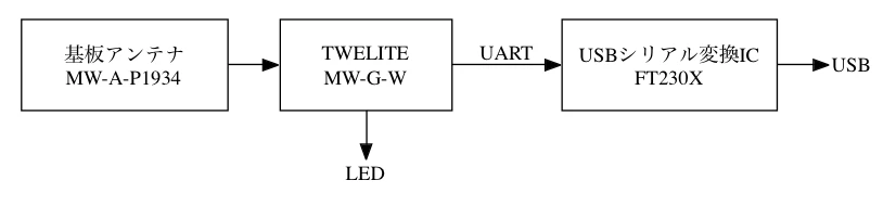
The TWELITE STICK USB dongle integrates the TWELITE module, antenna, and the functionality of the TWELITE R3 into a single case. As the successor to the MONOSTICK series, it is ideal for linking TWELITE with a PC.
For product specifications, please refer to the data sheet.
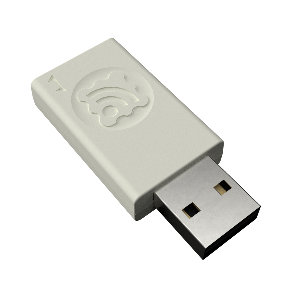
TWELITE STICK
USB Dongle
The TWELITE STICK combines the TWELITE module and antenna with the functionality of the TWELITE R series USB adapter.
TWELITE STICK Configuration
It can relay packets from other TWELITE devices to the PC, or from the PC to other TWELITE devices. It can also act as a repeater when connected to a USB power source.
Difference from MONOSTICK
TWELITE STICK is fully compatible with the same packets used in the previous MONOSTICK and functions as its successor.
Its compact size—comparable to that of a typical USB flash drive—makes it less likely to interfere with adjacent USB ports.
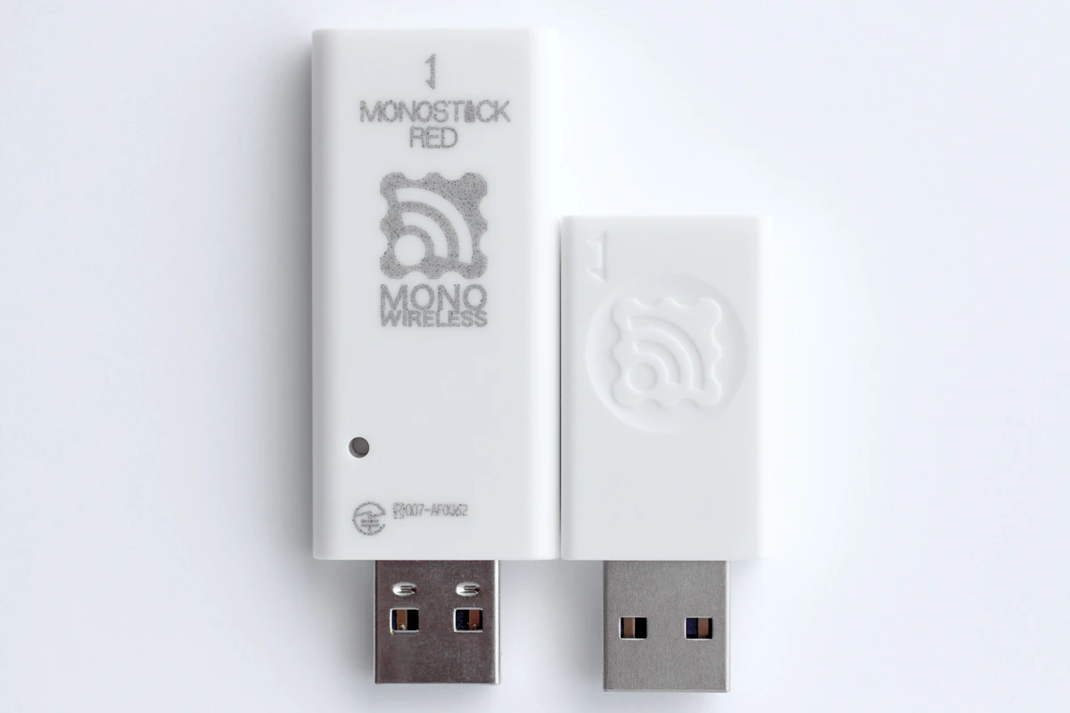
Size comparison between MONOSTICK and TWELITE STICK
By using the second-generation GOLD series for the TWELITE module, it achieves approximately 10mA lower current consumption during receive standby compared to the previous RED series, while maintaining equivalent transmission power and slightly improved receive sensitivity.
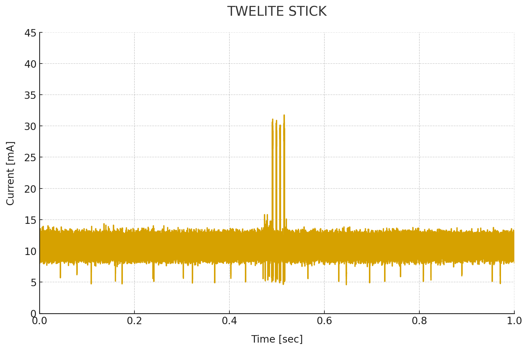
Current consumption from receive standby to transmission on TWELITE STICK
(4 retransmissions, LED disabled)
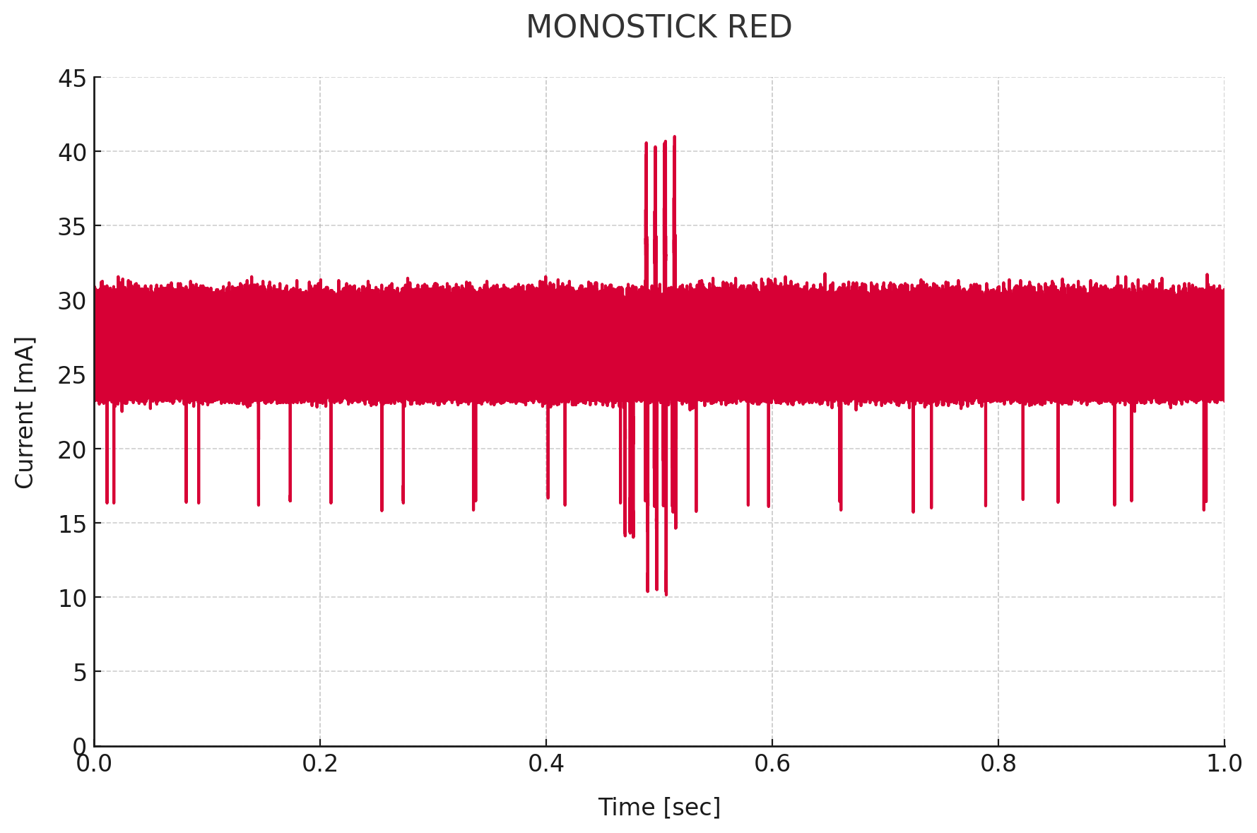
Current consumption from receive standby to transmission on MONOSTICK RED
(4 retransmissions)
Wireless packets of the TWELITE BLUE / RED / GOLD series are mutually compatible and can communicate with each other.
TWELITE APPS
The factory-shipped TWELITE STICK comes pre-installed with the TWELITE APPS Unified Edition. This unified edition takes advantage of the program size of the TWELITE GOLD series to consolidate the functions of previous firmware into a single image.
| Parent and Repeater App (App_Wings) | Serial Communication App (App_Uart) | OTA Configuration Apps (CUE / ARIA) |
|---|---|---|
| Communication with children and relaying | Wireless communication specialized for UART | Wireless configuration updates |
By using Interactive Mode operations, you can instantly switch between these functions without rewriting the firmware. Some apps change the logo LED color according to their state and blink when receiving packets.
| Parent | Repeater | Children |
|---|---|---|
 Magenta | 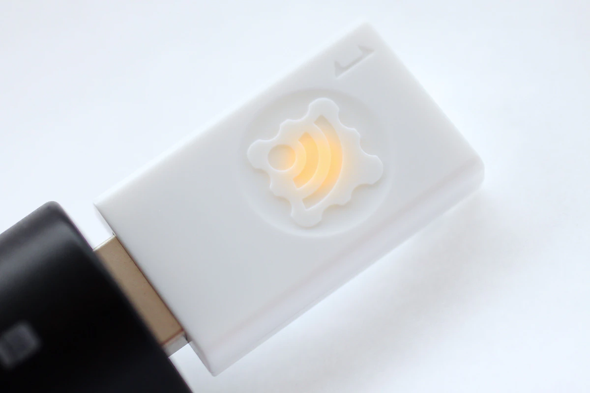 Yellow | 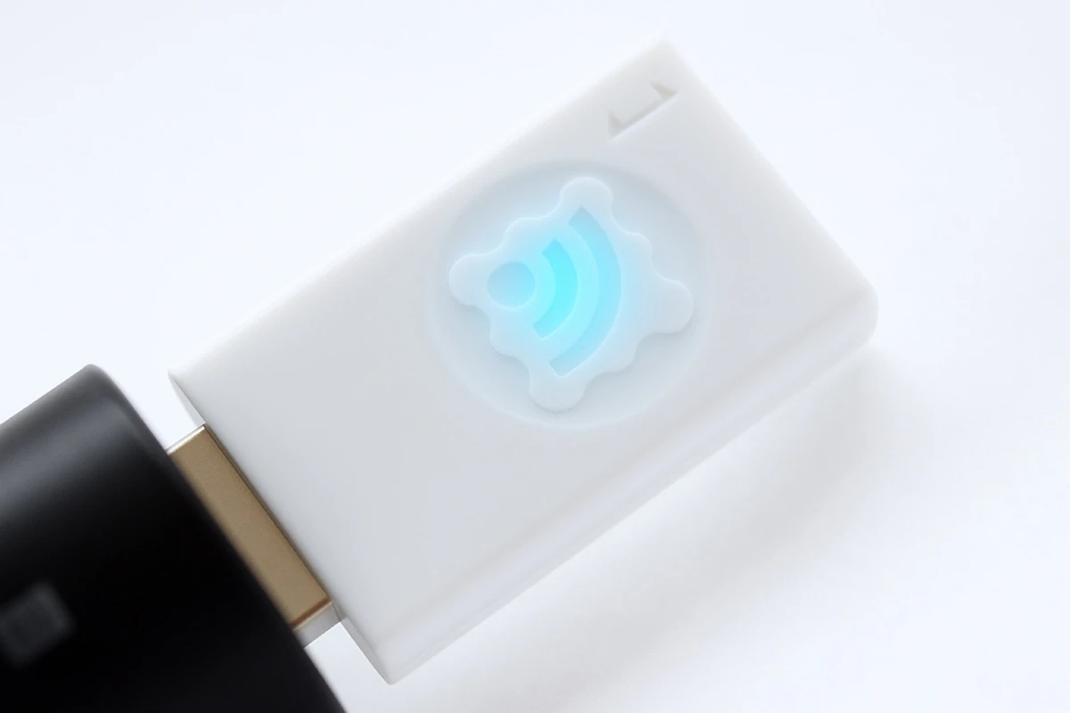 Cyan |
By default, the Parent and Repeater App (magenta LED) runs in parent mode, just like on MONOSTICK.
Simple Wireless Communication
TWELITE can communicate immediately after startup. Pairing like Bluetooth is not required.
Broadcast communication is performed between devices set to the same frequency channel. Therefore, multiple devices cannot transmit simultaneously on the same channel. Packets not addressed to the device are ignored. You can think of it as working like a transceiver or intercom.
TWELITE can transmit without receiving, enabling the realization of devices with excellent power-saving performance.
What is the wireless communication standard?
TWELITE is a wireless module that uses 2.4GHz radio waves and complies with IEEE 802.15.4, which is a different standard from Bluetooth (IEEE 802.15.1). Other products conforming to IEEE 802.15.4 include Zigbee modules, but TWELITE is not a Zigbee module. Zigbee modules use the Zigbee protocol stack on top of IEEE 802.15.4, whereas TWELITE implements a simple, proprietary protocol stack instead.
Although it is not suitable for large-volume data communication, it is optimal for simple signal transmission and similar applications.
Small amounts of data can be transmitted efficiently.
2.1 - Evaluation and Configuration with TWELITE STAGE APP
How to evaluate communication and change settings using TWELITE STAGE APP
By using the TWELITE STAGE APP included in the TWELITE STAGE SDK development and evaluation environment, you can verify communication and change settings.
Much of the content on this page is also applicable to the MONOSTICK series.
Basic Operation Check
Connect the TWELITE STICK
Connect the TWELITE STICK to the USB port of your PC.
The factory-shipped TWELITE is set to Parent mode of the Parent and Repeater App. It can send and receive data with child devices of the TWELITE series, and the logo mark should light up magenta.
Factory default state
Check the Startup Message
To verify the operation of the TWELITE STICK, first check the startup message output during boot.
TWELITE STICK communicates with the PC using UART at 115200bps / 8-N-1.
With TWELITE STICK connected, launch TWELITE_Stage from the MWSTAGE folder. On the “Serial Port Selection” screen, TWELITE STICK will be listed.
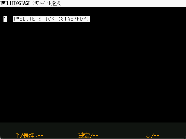
Serial Port Selection
If TWELITE STICK does not appear, try installing the FTDI D2XX driver.
On Windows, it appears as a COM port in Device Manager. On other systems, it appears as /dev/tty*.
When you select TWELITE STICK, the application proceeds to the main menu.
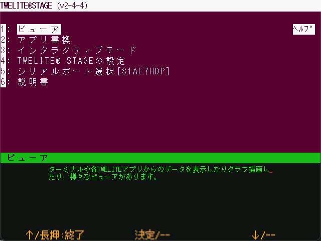
Main Menu
Selecting Viewer will take you to the viewer selection menu.
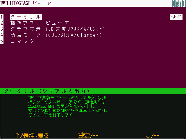
Viewer
To return to the previous screen, long press the bottom left of the screen or press the
ESC key.Selecting Terminal will open a VT-100 compatible terminal screen, just like a typical terminal application.
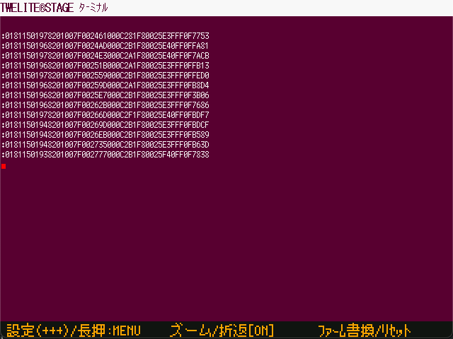
Terminal Screen
By default, TWELITE STICK may already be outputting received packet data, as shown above.
Long-press the Firmware Write/Reset button in the lower-right corner to reset the TWELITE.
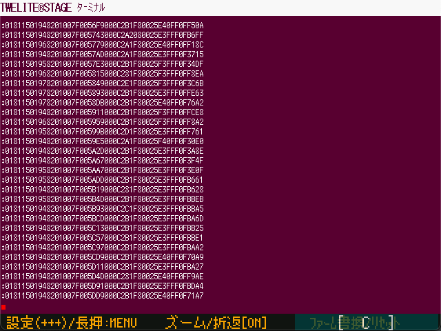
Long-press the lower-right corner to reset
A startup message will appear.
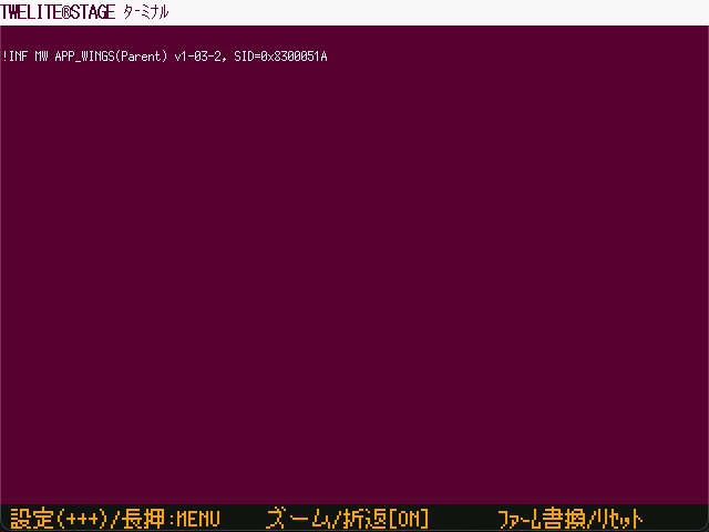
Example of Startup Message Output
In the example above, the following message is shown:
!INF MW APP_WINGS(Parent) v1-03-2, SID=0x8300051A
If you see !INF MW APP_WINGS(Parent) in the output, it indicates that the Parent mode of the Parent and Repeater App (App_Wings) is running.
TWELITE STICK has started successfully!
Communicating with a TWELITE DIP Child Device
This section describes how to verify communication with a child device using the TWELITE DIP.
The TWELITE DIP runs the Extremely Simple! Standard App (App_Twelite) that is written at the factory.
Preparing the TWELITE DIP
Connect a switch between DI1 and GND, and connect an LED between DO1 and VCC. This setup is the same as used in Basic Communication Between Terminals Using the Extremely Simple! Standard App.
Example wiring for child device
By using a TWELITE STICK in place of a TWELITE DIP parent, you can detect the button state on the PC side or control the LED from the PC.
Connecting the TWELITE STICK
Connect the TWELITE STICK to the USB port of your PC.
If it is set to Parent mode of the Parent and Repeater App, it will light up magenta.
Waiting in Parent Mode
Device Settings
No configuration changes are required. Communication will begin immediately using the factory default settings.
However, for confirmation, let’s check the current configuration.
To change TWELITE settings via UART, start the device in Interactive Mode. TWELITE STAGE APP provides functionality for working with Interactive Mode.
From the main menu, select Interactive Mode.
Main Menu
On the next screen, click anywhere or press the Enter key to continue.
Confirmation Screen
If the following screen appears, the mode has started successfully.
Interactive Mode
If the Channel value, which physically separates networks, is 18, and the Application ID value, which logically separates networks, is 67720102, communication with the factory-shipped TWELITE DIP will be possible.
How to Operate Interactive Mode
- Enter the ID shown on the left to edit each item (e.g., enter
ato edit the Application ID) - After selecting an item, type the value and press the
Enterkey to confirm, or press theESCkey to cancel - Press the
Skey to apply the settings you’ve entered - To reset all settings to default, press the
Rkey to reset, then press theSkey to apply
For details about each setting item, see the documentation for the Parent and Repeater App (App_Wings).
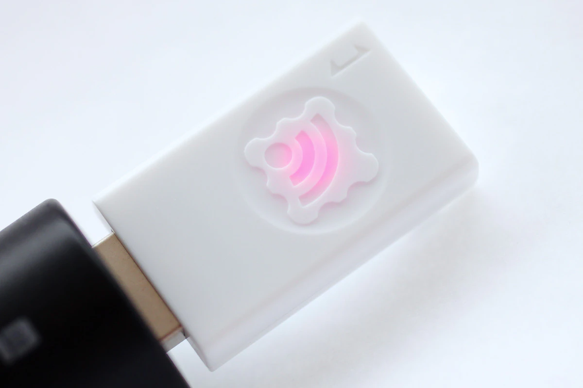
Logo Lighting
With the TWELITE STICK connected to your PC, press the switch connected to DI1 on the TWELITE DIP.
If operating correctly, the logo will glow red and brighter while the button is pressed.
Logo lights up red when DI1 is pressed
If a switch is connected to
DI2, the TWELITE STICK will glow green. If AI1 is disconnected from VCC and a voltage between 0–2V is applied, the brightness will vary depending on the button press on DI1 or DI2.Standard App Viewer
TWELITE STAGE APP includes a feature to display data received from child devices running the Extremely Simple! Standard App.
Let’s read the status of the switch connected to DI1.
From the main menu, select Viewer.
Main Menu
On the viewer selection screen, select Standard App Viewer.
Viewer Selection
The Standard App Viewer displays the latest data received by the TWELITE STICK from the Extremely Simple! Standard App.
Standard App Viewer
When you press the switch connected to DI1 on the TWELITE DIP, the D1 indicator will light up in red.
Standard App Viewer Items
Time CT: Timestamp of the packetId#: Logical Device ID of the child deviceSerial Number: Serial ID of the child device (engraved on the can)Dx: State of theDIxpinsAx: Voltage input to theAIxpins (inmV, ranging from0mVto2000mV)
Standard App Commander
TWELITE STAGE APP also includes a function to send data to child devices running the Extremely Simple! Standard App. Let’s try controlling the LED connected to DO1.
From the main menu, open Viewer.
Main Menu
On the viewer selection screen, choose Commander.
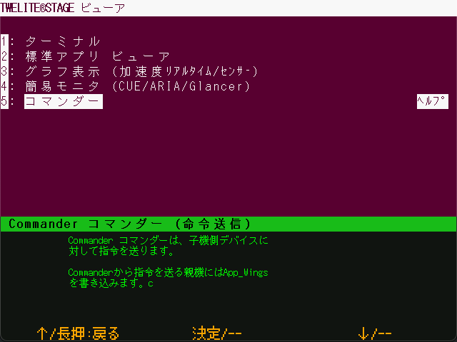
Viewer Selection
Select App_Twelite 0x80 Command.
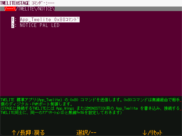
Standard App Commander
Click on DI1(1) or press the 1 key to control the lighting state of DI1.
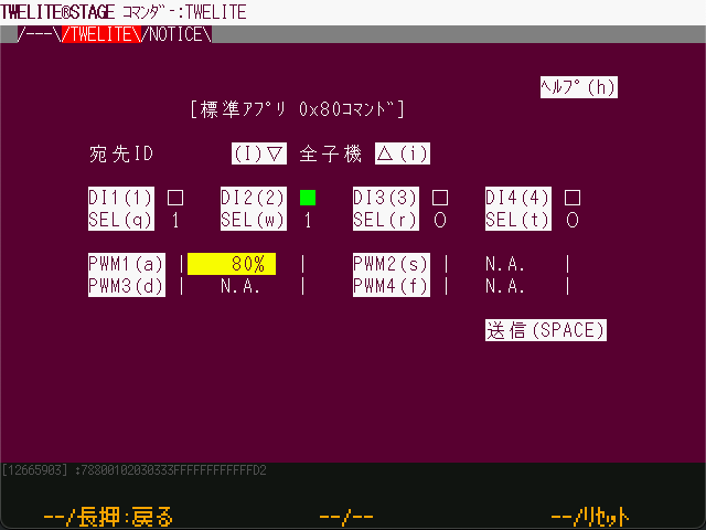
Commander Screen
Standard App Commander Items
Destination ID: Logical Device ID of the target device to which you want to send a state changeDIx(x): State change of the target device’sDOxpinSEL(x): Enable flag forDIx(x)PWMx(x): Change the duty cycle of the target device’sPWMxpinSend (SPACE): Re-send with the current state
You’ve successfully confirmed the TWELITE STICK’s settings and its communication with a TWELITE DIP child device!
Communicating with TWELITE ARIA
This section describes how to verify communication with the temperature and humidity sensor tag TWELITE ARIA.
TWELITE ARIA runs the ARIA App (App_ARIA) that is written at the factory.
Preparing TWELITE ARIA
Insert a CR2032 battery into the TWELITE ARIA.
Insert CR2032 battery
By using a TWELITE STICK as the parent device for TWELITE ARIA, you can obtain temperature, humidity, and magnetic proximity data on your PC.
Connecting the TWELITE STICK
Connect the TWELITE STICK to the USB port of your PC.
If it is set to Parent mode of the Parent and Repeater App, it will light up magenta.
Waiting in Parent Mode
Device Settings
No configuration changes are needed. Communication will start immediately with the factory default settings.
If the Channel, which physically separates networks, is set to 18, and the Application ID, which logically separates networks, is set to 67720102, then communication with the factory-configured TWELITE ARIA is possible.
Logo Lighting
With TWELITE STICK connected to the PC, bring a magnet close to the Hall sensor on TWELITE ARIA.
If working properly, TWELITE ARIA will send a packet each time a magnet is brought near, and TWELITE STICK’s logo will flash in response.
The logo will flash not only for ARIA packets but for any packets with the same channel and application ID.
Simple Monitor
TWELITE STAGE APP includes a simple monitor feature to display data received from TWELITE ARIA.
From the main menu, select Viewer.
Main Menu
On the viewer selection screen, choose Simple Monitor (CUE/ARIA/Glancer).
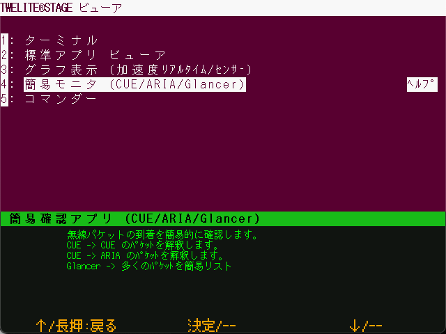
Viewer Selection
Next, select Simple Monitor for TWELITE ARIA.
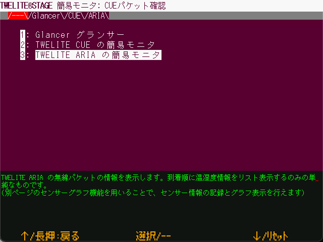
Simple Monitor Selection Screen
The Simple Monitor screen displays the latest data received by the TWELITE STICK from TWELITE ARIA.
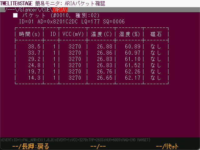
Simple Monitor
When a magnet is brought close to TWELITE ARIA, a new packet is received.
Simple Monitor Items
Packet: Information of the latest packet#: Packet sequence number (includes all types)Type: Packet type ID (fixed as02)ID: Logical Device IDAD: Serial ID (engraved on the can of the device)LQ: Link Quality Indicator (LQI, higher is better, range: 0–255)SQ: Packet sequence number based on TWELITE ARIA data
- History
Time: Timestamp when received (not included in packet)ID: Logical Device IDVCC(mV): Supply voltage of TWELITE ARIATemp(C): TemperatureHumidity(%): Relative humidityMagnet: Hall sensor result (None,[N],[S])
Sensor Graph
TWELITE STAGE APP includes a feature to graphically display temperature and humidity data received from child devices.
From the main menu, open Viewer.
Main Menu
On the viewer selection screen, select Graph View (Accelerometer Real-Time / Sensor).
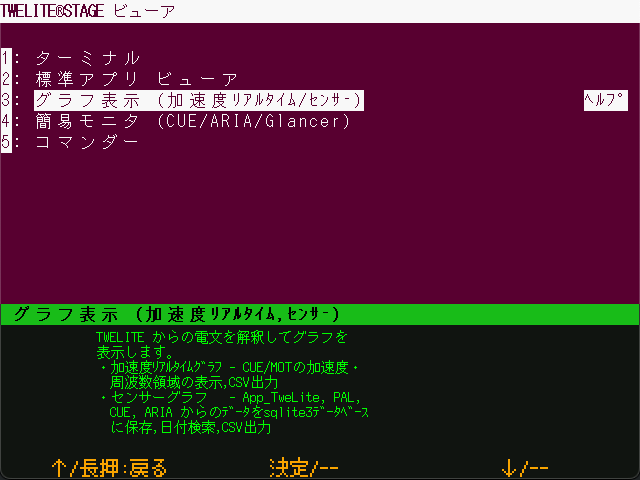
Viewer Selection
Next, select Sensor Graph.
Graph Selection Screen
From the list of nodes on the right, select one that begins with ARA.
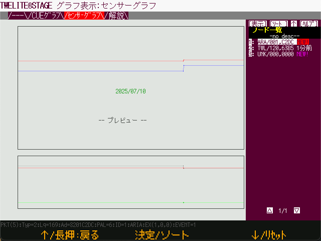
Node Selection
By default, data for the past 24 hours is displayed. To view the most recent data, click [Live >>].
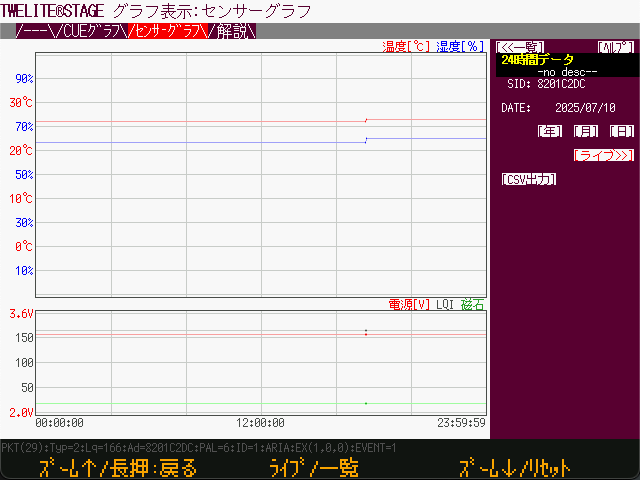
24-Hour Data
The latest data will be displayed. Bring a magnet close to the sensor or warm the sensor near the 7P interface to observe the changes in values.
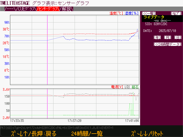
Live Data
For more details on the Sensor Graph, refer to the TWELITE STAGE APP Manual.
Communication with TWELITE ARIA has been successfully verified!
2.2 - Communicating with Child Devices Using Python (Basic)
How to communicate with child devices using Python
By using a dedicated library, you can communicate with TWELITE child devices via TWELITE STICK from Python.
Much of the content on this page also applies to the MONOSTICK series.
Basic Operation Check
Connect the TWELITE STICK
Connect the TWELITE STICK to your PC’s USB port.
The factory-default TWELITE is configured in Parent mode of the Parent and Repeater App. It can send and receive data to and from child devices in the TWELITE series, and the logo should light up magenta.
Factory default state
Installing the MWings Library
Prepare a Python 3.12 or later environment.
Install the MWings module, which interprets the output of the Parent and Repeater App.
pip install mwings
The MWings module allows communication with TWELITE child devices via a TWELITE parent device connected to the host.
- Interprets data received from the parent and converts it into a dictionary, JSON, or pandas DataFrame format*
- Sends commands generated from dictionaries to the parent device
*The Lite version does not support pandas
For detailed installation instructions and full feature documentation, refer to the MWings for Python Manual.
In modern Python development, managing Python versions and project-level dependencies is essential. The manual introduces how to set up an environment using pyenv and poetry.
For Raspberry Pi, please use the Lite version mwingslite module.
This version removes the dependency on pandas, avoiding potential conflicts with numpy. Although it does not support DataFrame output, it retains output functions for dictionaries and JSON strings.
Because of its lightweight nature, it can also be a good option on regular PCs if you do not need pandas functionality.
Confirming Data Reception
Verify that TWELITE STICK can interpret the received data.
Please run the sample script rx_print_json.py available on GitHub.
This script will print the contents of all types of packets received by the TWELITE STICK in JSON format to the terminal, allowing you to confirm the data.
# -*- coding:utf-8 -*-
# Written for Python 3.12
# Formatted with Black

# MWings example: Receive data, print JSON, typed

from zoneinfo import ZoneInfo

import mwings as mw


# Main function
def main() -> None:
    # Create a twelite object
    twelite = mw.Twelite(mw.utils.ask_user_for_port())

    # Use JST for received data
    twelite.set_timezone(ZoneInfo("Asia/Tokyo"))

    # Register event handlers
    @twelite.on(mw.common.PacketType.APP_ARIA)
    def on_app_aria(packet: mw.parsers.app_aria.ParsedPacket) -> None:
        print(packet.to_json(verbose=False, spread=True))

    @twelite.on(mw.common.PacketType.APP_CUE)
    def on_app_cue(packet: mw.parsers.app_cue.ParsedPacket) -> None:
        print(packet.to_json(verbose=False, spread=True))

    @twelite.on(mw.common.PacketType.APP_CUE_PAL_EVENT)
    def on_app_cue_pal_event(packet: mw.parsers.app_cue_pal_event.ParsedPacket) -> None:
        print(packet.to_json(verbose=False, spread=True))

    @twelite.on(mw.common.PacketType.APP_IO)
    def on_app_io(packet: mw.parsers.app_io.ParsedPacket) -> None:
        print(packet.to_json(verbose=False, spread=True))

    @twelite.on(mw.common.PacketType.APP_TWELITE)
    def on_app_twelite(packet: mw.parsers.app_twelite.ParsedPacket) -> None:
        print(packet.to_json(verbose=False, spread=True))

    @twelite.on(mw.common.PacketType.APP_PAL_AMB)
    def on_app_pal_amb(packet: mw.parsers.app_pal_amb.ParsedPacket) -> None:
        print(packet.to_json(verbose=False, spread=True))

    @twelite.on(mw.common.PacketType.APP_PAL_MOT)
    def on_app_pal_mot(packet: mw.parsers.app_pal_mot.ParsedPacket) -> None:
        print(packet.to_json(verbose=False, spread=True))

    @twelite.on(mw.common.PacketType.APP_PAL_OPENCLOSE)
    def on_app_pal_openclose(packet: mw.parsers.app_pal_openclose.ParsedPacket) -> None:
        print(packet.to_json(verbose=False, spread=True))

    @twelite.on(mw.common.PacketType.APP_UART_ASCII)
    def on_app_uart_ascii(packet: mw.parsers.app_uart_ascii.ParsedPacket) -> None:
        print(packet.to_json(verbose=False, spread=True))

    @twelite.on(mw.common.PacketType.APP_UART_ASCII_EXTENDED)
    def on_app_uart_ascii_extended(
        packet: mw.parsers.app_uart_ascii_extended.ParsedPacket,
    ) -> None:
        print(packet.to_json(verbose=False, spread=True))

    @twelite.on(mw.common.PacketType.ACT)
    def on_act(packet: mw.parsers.act.ParsedPacket) -> None:
        print(packet.to_json(verbose=False, spread=True))

    # Start receiving
    try:
        # Set as daemon thread
        twelite.daemon = True
        # Start the thread, Join to the main thread
        twelite.start()
        print("Started receiving")
        while True:
            twelite.join(0.5)
    except KeyboardInterrupt:
        # Stop the thread
        print("Flushing...")
        twelite.stop()
        print("Completed")


if __name__ == "__main__":
    # Call the main function
    main()
For example, if you have prepared a factory-default TWELITE DIP running the Extremely Simple! Standard App as a child device, just like in the previous section Using TWELITE STAGE APP, you should see an output like the following. To stop the script, press Ctrl+C.
{
  "time_parsed": "2025-07-11T11:45:02.067804+09:00",
  "packet_type": "APP_TWELITE",
  "sequence_number": 4713,
  "source_serial_id": "8201007F",
  "source_logical_id": 120,
  "lqi": 166,
  "supply_voltage": 3254,
  "destination_logical_id": 0,
  "relay_count": 0,
  "periodic": true,
  "di_changed_1": false,
  "di_changed_2": false,
  "di_changed_3": false,
  "di_changed_4": false,
  "di_state_1": false,
  "di_state_2": false,
  "di_state_3": false,
  "di_state_4": false,
  "ai_voltage_1": 2000,
  "ai_voltage_2": 2000,
  "ai_voltage_3": 2000,
  "ai_voltage_4": 2000
}
Contents of JSON string
mwings.parsers.app_twelite.ParsedPacket
| Key | Value Description |
|---|---|
time_parsed | Reception time (default UTC, ISO8601 format) |
packet_type | Packet type |
sequence_number | Sequence number (represents time for App_Twelite) |
source_serial_id | Sender serial ID |
source_logical_id | Sender logical device ID |
lqi | Link Quality Indicator (8-bit) |
supply_voltage | Supply voltage (mV) |
destination_logical_id | Destination logical device ID |
relay_count | Relay count |
periodic | Indicates whether it is a periodic transmission |
di_changed | Whether each digital input has changed |
di_state | Current state of each digital input |
ai_voltage | Voltage at each analog input |
mwings_implementation | MWings implementation details (for future use) |
mwings_version | MWings library version |
hostname | Hostname of the receiver |
system_type | System type of the receiver host |
When spread=True, list-type fields are split into keys like _1, _2, etc.
The received data is displayed in mixed format.
A sample script rx_export_csv_durable.py is also available for logging data to a CSV file.
It is useful as a command-line tool for logging received data over extended periods.
python rx_export_csv_durable.py -h
usage: rx_export_csv_durable.py [-h] [-v] [-s]

Log packets from App_Wings to csv, line by line

options:
  -h, --help     show this help message and exit
  -v, --verbose  include system information
  -s, --sort     sort columns in the output
Sending and Receiving Arbitrary Data
Here, let’s create a script that specifically communicates with a TWELITE DIP child device prepared just like in Using TWELITE STAGE APP.
Example wiring of TWELITE DIP child device
The goal is to display the state of a switch connected to the DI1 pin of the TWELITE DIP and control an LED connected to the DO1 pin.
Receiving Only Standard App Data
Modify rx_print_json.py to create a simplified script that only receives data from the Extremely Simple! Standard App.
# -*- coding:utf-8 -*-

from zoneinfo import ZoneInfo

import mwings as mw


# Main function
def main() -> None:
    # Create a twelite object
    twelite = mw.Twelite(mw.utils.ask_user_for_port())

    # Use JST for received data
    twelite.set_timezone(ZoneInfo("Asia/Tokyo"))

    # Register event handlers
    @twelite.on(mw.common.PacketType.APP_TWELITE)
    def on_app_twelite(packet: mw.parsers.app_twelite.ParsedPacket) -> None:
        print(packet.to_json(verbose=False, spread=True))

    # Start receiving
    try:
        # Set as daemon thread
        twelite.daemon = True
        # Start the thread, Join to the main thread
        twelite.start()
        print("Started receiving")
        while True:
            twelite.join(0.5)
    except KeyboardInterrupt:
        # Stop the thread
        print("Flushing...")
        twelite.stop()
        print("Completed")


if __name__ == "__main__":
    # Call the main function
    main()
Script Mechanism
By calling twelite.start(), a thread for receiving is launched, and twelite.on registers an event handler for each application type (in this case, on_app_twelite()), which is invoked upon each packet reception.
For a detailed explanation, refer to Script Breakdown in the MWings for Python Manual.
Extracting Specific Values
In the previous script, we used the to_json() method to output all data as a JSON string.
Here, we’ll extract only the state of the DI1 pin from parsers.app_twelite.ParsedPacket using the di_state field and display a virtual LED in the terminal.
Rewrite the on_app_twelite() handler as follows:
def on_app_twelite(packet: mw.parsers.app_twelite.ParsedPacket) -> None:
        print(f"\rDO1 LED: {"🔴" if packet.di_state[0] else "⚪"}", end='', flush=True)
If pressing the switch connected to the DI pin of TWELITE DIP causes the red light to appear, it indicates success.
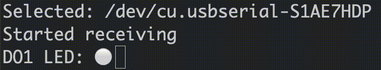
Example display
Sending Commands to the Parent Device
In addition to displaying data received by the TWELITE STICK, you can also send data from the TWELITE STICK.
In the script’s main loop, we call threading.Thread.join() every 0.5 seconds so that the receiving thread can also terminate when the main thread ends.
        # Start the thread, Join to the main thread
        twelite.start()
        print("Started receiving")
        while True:
            twelite.join(0.5)
Using this mechanism, let’s control the DO1 pin of the TWELITE DIP from the main loop and try blinking the LED every 0.5 seconds.
Modify the previous script as follows. The full script below includes all changes made so far.
# -*- coding:utf-8 -*-

from zoneinfo import ZoneInfo
from typing import Any

import mwings as mw


# Main function
def main() -> None:
    # Create a twelite object
    twelite = mw.Twelite(mw.utils.ask_user_for_port())

    # Use JST for received data
    twelite.set_timezone(ZoneInfo("Asia/Tokyo"))

    # Register event handlers
    @twelite.on(mw.common.PacketType.APP_TWELITE)
    def on_app_twelite(packet: mw.parsers.app_twelite.ParsedPacket) -> None:
        print(f"\rDO1 LED: {"🔴" if packet.di_state[0] else "⚪"}", end='', flush=True)

    # Initialize command
    initial: dict[str, Any] = {
        "destination_logical_id": 0x78,  # All child devices
        "di_to_change": [True, False, False, False],  # Enable DI1
        "di_state": [False, False, False, False],  # Initial state of DIx
    }
    command = mw.serializers.app_twelite.Command(**initial)

    # Toggle the DI1 state
    def toggle_di1() -> None:
        command.di_state[0] = not command.di_state[0]
        twelite.send(command)

    # Start receiving
    try:
        # Set as daemon thread
        twelite.daemon = True
        # Start the thread, Join to the main thread
        twelite.start()
        print("Started receiving")
        while True:
            toggle_di1() # Send
            twelite.join(0.5) # Receive
    except KeyboardInterrupt:
        # Stop the thread
        print("Flushing...")
        twelite.stop()
        print("Completed")


if __name__ == "__main__":
    # Call the main function
    main()
Script Mechanism
First, the contents of serializers.app_twelite.Command are initialized. Then, a closure toggle_di1() is defined to invert di_state[0] and send it. By calling toggle_di1() from the main loop, the LED is made to blink.
When you run this script, it displays a virtual LED just like before.
Example display
At the same time, the LED connected to the DO1 pin of TWELITE DIP should continuously blink. When you stop the script, the blinking stops.
Packet reception and command transmission can be handled asynchronously.
2.2.1 - Communicating with Child Devices Using Python (Web Server IoT)
Send data from child devices to a web server using Python
As a practical application, this guide demonstrates how to build an IoT system using a web server.
The content on this page also applies to the MONOSTICK series.
Collecting Temperature and Humidity Data from TWELITE ARIA
Let’s build a simple IoT system that receives temperature and humidity data from the sensor tag TWELITE ARIA, sends it to a web server, and displays it on a graph.
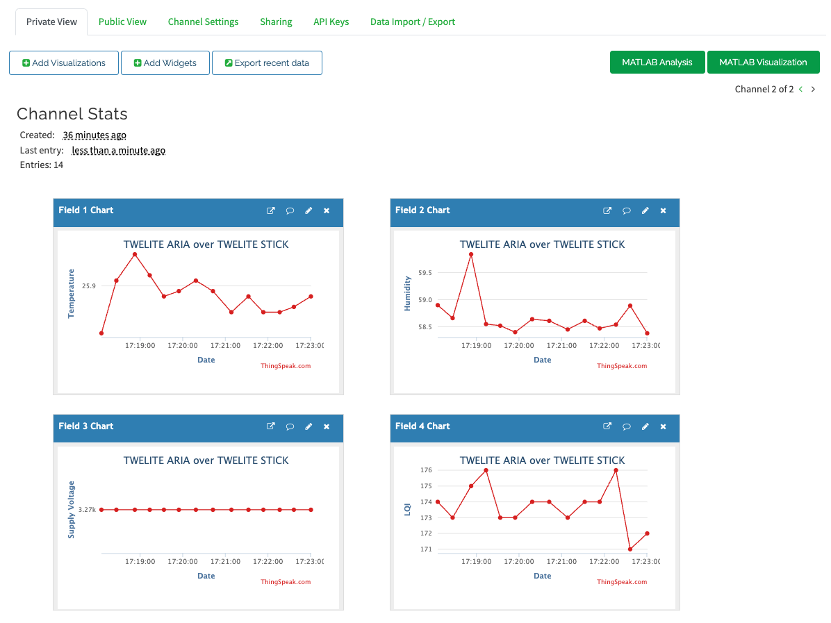
ThingSpeakの表示例
This can be accomplished with just 85 lines of Python script.
In the basic script for TWELITE DIP, we only performed simple operations on DI1 and DO1. However, in an actual IoT system, it is necessary to send acquired data to an upstream server using methods such as REST APIs.
About ThingSpeak
Here, we will use ThingSpeak, a service by MathWorks, in combination with the MWings library.
ThingSpeak is an IoT analytics service provided by MathWorks, the developer of MATLAB and Simulink.
As of July 2025, it is free to use as long as the data volume is within certain limits and not for commercial use.
Creating an Account
Visit the ThingSpeak website and create a MathWorks account.
Creating a Channel
Create a “Channel” and configure it as shown below (the “Name” and “Description” can be arbitrary).
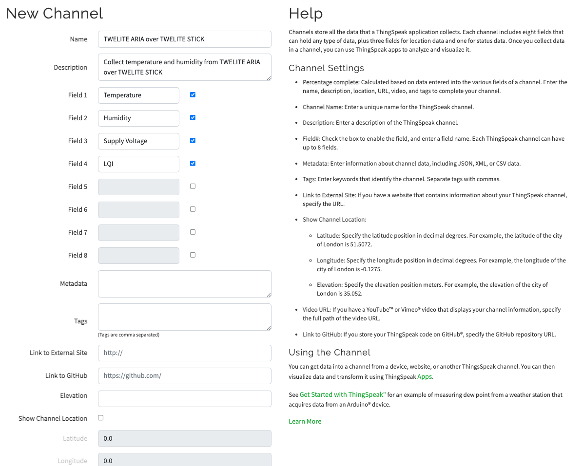
Channel Configuration Example
Since data is sent using field numbers, the order of
Field x matters.Obtaining API Keys
Go to the “API Keys” tab on the Channel page and note down the 16-character “Write API key”.
Configuring and Starting TWELITE ARIA
Changing Settings for TWELITE ARIA
Change the settings of TWELITE ARIA and set the Transmission Interval of TWELITE ARIA Mode to 20 seconds or more (to avoid overloading the server).
There are two ways to change TWELITE ARIA settings:
- Temporarily switch TWELITE STICK to OTA mode (ARIA) and configure wirelessly
- Use a TWELITE R2/R3 via USB connection and configure via wired connection
The former does not require TWELITE R2/R3, while the latter allows smoother operation.
Starting TWELITE ARIA
Insert a CR2032 battery to power up TWELITE ARIA.
Insert CR2032 battery
Writing and Running the Script
Installing Required Modules
Prepare Python 3.12 or later and install the mwings (or mwingslite) and requests modules.
pip install mwings requests
Creating the Script
Create the script stick_aria_thingspeak.py as shown below. Use mwings.parsers.app_aria to receive data and the requests module to send HTTP GET requests to ThingSpeak.
Replace the initial
API_KEY with the key you saved earlier.
# -*- coding:utf-8 -*-

from zoneinfo import ZoneInfo
from time import perf_counter

import mwings as mw
import requests


API_KEY = "XXXXXXXXXXXXXXXX"  # Replace with your ThingSpeak API key
BASE_URL = "https://api.thingspeak.com/update"
SEND_MIN_INTERVAL = 20  # Minimum interval in seconds to send data to ThingSpeak


# Main function
def main() -> None:
    # Create a twelite object
    twelite = mw.Twelite(mw.utils.ask_user_for_port())

    # Use JST for received data
    twelite.set_timezone(ZoneInfo("Asia/Tokyo"))

    # Initialize last send time
    last_send_time = perf_counter() - SEND_MIN_INTERVAL

    # Initialize the target serial ID
    target_serial_id = -1

    # Register event handlers
    @twelite.on(mw.common.PacketType.APP_ARIA)
    def on_app_aria(packet: mw.parsers.app_aria.ParsedPacket) -> None:

        # Filter packets by serial ID
        if target_serial_id < 0:
            # Set the serial ID from the received packet
            target_serial_id = packet.source_serial_id
            print(f"Serial ID set to {target_serial_id:08X}")
        elif packet.source_serial_id != target_serial_id:
            # Ignore packets from other serial ID devices
            print(
                f"Ignoring packet from serial ID {packet.source_serial_id:08X}, expected {target_serial_id:08X}"
            )
            return

        # Throttle sending to ThingSpeak
        if perf_counter() - last_send_time < SEND_MIN_INTERVAL:
            print("Skipping send due to minimum interval")
            return  # Skip sending if within the minimum interval
        last_send_time = perf_counter()  # Update last send time

        # Send data to ThingSpeak
        payload = {
            "api_key": API_KEY,
            "field1": f"{packet.temp_100x / 100.0:.2f}",  # Temperature
            "field2": f"{packet.humid_100x / 100.0:.2f}",  # Humidity
            "field3": f"{packet.supply_voltage}",  # Supply voltage (mV)
            "field4": f"{packet.lqi}",  # Link Quality Indicator
        }
        response = requests.get(BASE_URL, params=payload)

        # Check the response status
        if response.status_code == 200:
            print(f"OK: entry ID = {response.text}")
        else:
            print(f"NG: status code = {response.status_code}")

    # Start receiving
    try:
        # Set as daemon thread
        twelite.daemon = True
        # Start the thread, Join to the main thread
        twelite.start()
        print("Started receiving")
        while True:
            twelite.join(0.5)  # Receive
    except KeyboardInterrupt:
        # Stop the thread
        print("Flushing...")
        twelite.stop()
        print("Completed")


if __name__ == "__main__":
    # Call the main function
    main()
Running the Script
Execute the script.
python stick_aria_thingspeak.py
If data is successfully received from TWELITE ARIA and sent correctly, you will see the following output showing entry IDs in sequence:
Started receiving
Serial ID set to 8201C2DC
OK: entry ID = 1
OK: entry ID = 2
OK: entry ID = 3
OK: entry ID = 4
OK: entry ID = 5
...
Click the “Private View” tab on ThingSpeak. The transmitted data should appear as a graph.
By default, the Y-axis range adjusts dynamically. You can configure the min and max values for each graph via the ✏️ icon.
For example, based on the operating voltage of TWELITE, you can set
Y-Axis Min and Y-Axis Max for the Field 3 Chart.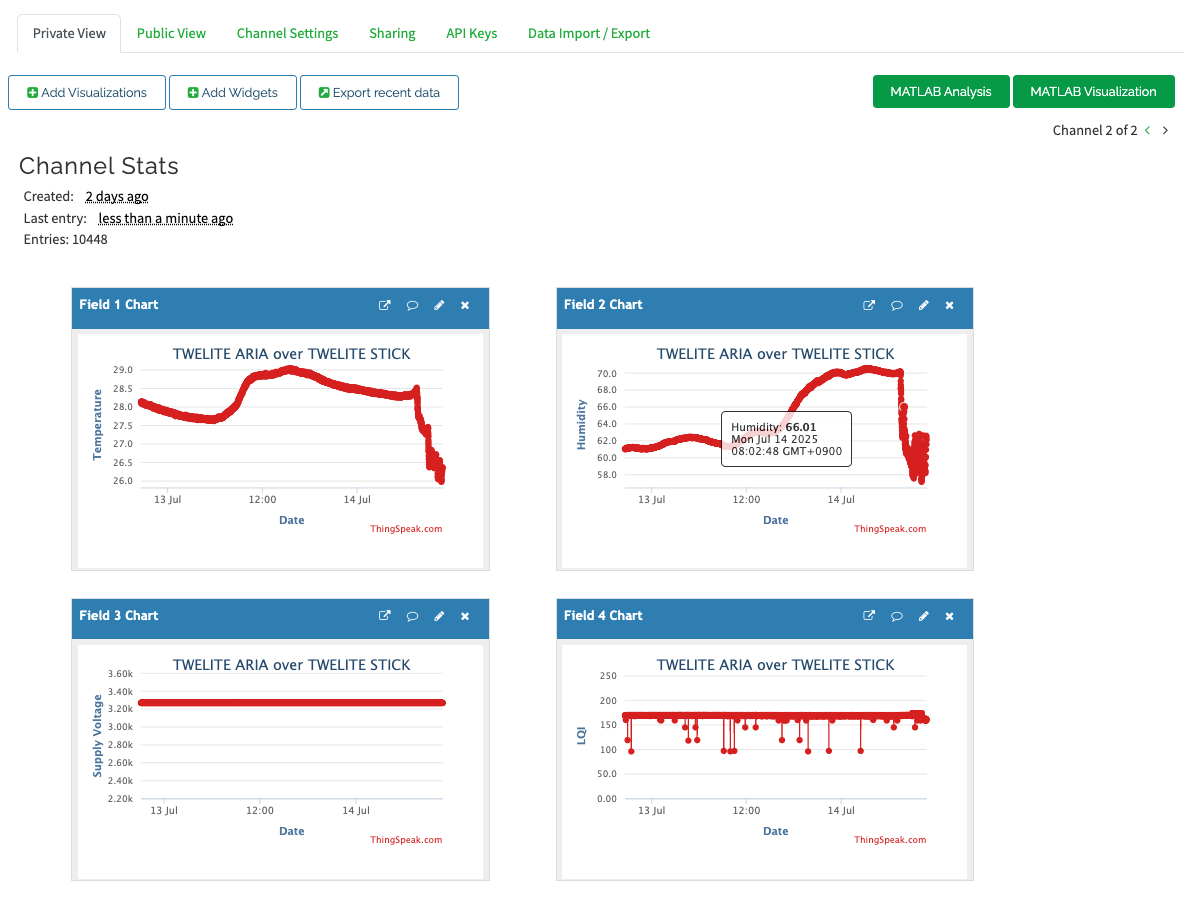
Displaying approximately 2 days of data
You’ve successfully built a simple IoT system integrated with a web server!
Script Overview
Filtering for Sending and Receiving
- To prevent overloading the server, data is sent only at intervals defined by
SEND_MIN_INTERVAL. - To avoid mixing data from multiple devices, the serial ID of the first device is used as the target.
The data sent to the server is constructed in the following section:
# Send data to ThingSpeak
payload = {
    "api_key": API_KEY,
    "field1": f"{packet.temp_100x / 100.0:.2f}",  # Temperature
    "field2": f"{packet.humid_100x / 100.0:.2f}",  # Humidity
    "field3": f"{packet.supply_voltage}",  # Supply voltage (mV)
    "field4": f"{packet.lqi}",  # Link Quality Indicator
}
response = requests.get(BASE_URL, params=payload)
From mwings.parsers.app_aria, we retrieve the temperature, humidity, coin cell voltage, and signal quality (LQI) expressed as a value between 0 and 255, then convert these to strings to construct the query for the GET request.
2.2.2 - Communicating with Child Devices Using Python (Graphical UI)
Build an application with a graphical UI to communicate with child devices using Python
As a practical example, we will create an application with a simple graphical user interface.
The content on this page also applies to the MONOSTICK series.
Communicating with TWELITE DIP
Let’s build an application to communicate with the TWELITE DIP, featuring a simple user interface.
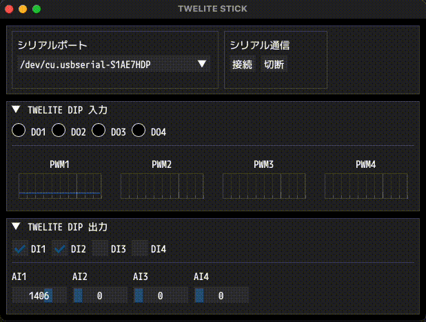
Example of screen display
This can be accomplished with just 433 lines of Python script.
In the basic script for TWELITE DIP, we only performed simple operations with DI1 and DO1. However, applications designed for actual monitoring require a user interface like the one found in TWELITE STAGE APP.
About Dear PyGui
Here, we will use a combination of Dear PyGui and the MWings library.
Dear PyGui (DPG) is a UI toolkit based on Dear ImGui written in C++ and OpenGL.
It is commonly used in development tool interfaces. While it is not suited for highly customized designs, it features lightweight performance and simple syntax.
Wiring and Starting the TWELITE DIP
In this application, when a signal is received via DIx or AIx of the TWELITE DIP, a signal is simultaneously output to DOx or PWMx.
In addition to VCC and GND, freely connect any of the following 16 pins:
| Type | Pin | 1 | 2 | 3 | 4 | Range | Notes |
|---|---|---|---|---|---|---|---|
| Digital Input | DIx | #15 | #16 | #17 | #18 | 0.0V - VCC | Internal pull-up |
| Analog Input | AIx | #22 | #23 | #24 | #25 | 0.0V - 2.0V | Invalid if exceeded |
| Digital Output | DOx | #5 | #8 | #9 | #12 | 0.0V - VCC | Connect LED cathode |
| PWM Output | PWMx | #4 | #6 | #7 | #11 | 0% - 100% | Voltage at VCC level |
Creating and Running the Script
Installing Modules
Install the mwings (or mwingslite) and dearpygui modules.
pip install mwings dearpygui
Creating the Script
Create the script stick_dip_gui.py as described below. It uses mwings.parsers.app_twelite to receive data and mwings.serializers.app_twelite to send data, with a GUI provided via dearpygui.
A font file can be used to display components.
In this example, it is assumed that Mplus1Code-Medium.otf from M PLUS FONTS is located in the same directory.
Project
├ stick_dip_gui.py
└ Mplus1Code-Medium.otf
# -*- coding:utf-8 -*-
from time import perf_counter
from enum import IntEnum, auto
from zoneinfo import ZoneInfo
from typing import Any, Self, final
from types import TracebackType
from pathlib import Path
from collections import deque
import mwings as mw
import dearpygui.dearpygui as dpg # type: ignore
PLOT_UPDATE_INTERVAL = 1.0 / 100 # 100Hz
PLOT_X_LIMIT = 5.0 # 3 seconds
FONT = "Mplus1Code-Medium.otf"
# MARK: MainViewport
@final
class MainViewport:
@final
class State(IntEnum):
"""Application state enumeration."""
IDLE = auto()
CONNECTING = auto()
selected_port: str
twelite: mw.Twelite
command_app_twelite: mw.serializers.app_twelite.Command
pwm_data: dict[int, int]
pwm_plot_data: dict[int, deque[tuple[float, int]]]
last_plot: float
state: State
theme_disabled: int
def __init__(self) -> None:
"""Initialize the main window and prepare all components."""
self.initialize_viewport()
self.create_themes()
self.create_windows()
self.initialize()
self.update_state(self.State.IDLE)
def create_themes(self) -> None:
"""Create a visual theme for disabled UI elements."""
with dpg.theme() as self.theme_disabled:
with dpg.theme_component(dpg.mvAll):
dpg.add_theme_color(dpg.mvThemeCol_Text, (150, 150, 150, 255))
dpg.add_theme_color(dpg.mvThemeCol_TextDisabled, (100, 100, 100, 255))
dpg.add_theme_color(dpg.mvThemeCol_FrameBg, (5, 5, 5, 255))
# MARK: Initialize Viewport
def initialize_viewport(self) -> None:
"""Set up Dear PyGui context, fonts, and viewport."""
dpg.create_context()
with dpg.font_registry():
font_path = str(Path(__file__).parent / FONT)
with dpg.font(file=font_path, size=18) as default_font:
dpg.add_font_range_hint(dpg.mvFontRangeHint_Japanese)
dpg.bind_font(default_font)
dpg.create_viewport(
title="TWELITE STICK", width=620, height=440, resizable=True
)
dpg.set_viewport_vsync(False)
dpg.setup_dearpygui()
dpg.show_viewport()
def create_windows(self) -> None:
"""Create and configure all Dear PyGui windows and their contents."""
# MARK: Panel Window
with dpg.window(
no_title_bar=True,
no_close=True,
no_collapse=True,
no_move=True,
no_resize=True,
pos=(10, 10),
width=600,
height=100,
):
ports = mw.utils.get_ports()
with dpg.group(horizontal=True):
with dpg.child_window(width=300):
dpg.add_text("Serial Port")
dpg.add_combo(
items=ports,
default_value=ports[0],
tag="ports_combo",
width=280,
enabled=True,
callback=self.on_select_port,
)
with dpg.child_window(width=150):
dpg.add_text("Transmission")
with dpg.group(horizontal=True):
dpg.add_button(
label="Connect",
tag="start_button",
enabled=True,
callback=self.on_start,
)
dpg.add_button(
label="Disconnect",
tag="stop_button",
enabled=False,
callback=self.on_stop,
)
# MARK: Input Window
with dpg.window(
label="TWELITE DIP Input",
no_close=True,
# no_resize=True,
pos=(10, 120),
width=600,
height=160,
tag="window_twelite_dip_input",
):
with dpg.group(horizontal=False):
# DOx
with dpg.group(horizontal=True):
for p in range(1, 5):
with dpg.group(horizontal=True):
with dpg.drawlist(
width=20, height=20, tag=f"indicator_do{p}"
):
dpg.draw_circle(
center=(10, 10),
radius=10,
fill=(0, 0, 0, 255),
tag=f"circle_do{p}",
)
dpg.add_text(f"DO{p}")
dpg.add_spacer()
dpg.add_separator()
dpg.add_spacer()
# PWMx
with dpg.group(horizontal=True):
for p in range(1, 5):
with dpg.plot(
label=f"PWM{p}",
height=80,
width=140,
tag=f"plot_pwm{p}",
no_frame=True,
no_mouse_pos=True,
):
dpg.add_plot_axis(
dpg.mvXAxis,
tag=f"plot_pwm{p}_x",
no_tick_labels=True,
)
with dpg.plot_axis(
dpg.mvYAxis,
tag=f"plot_pwm{p}_y",
no_tick_labels=True,
no_tick_marks=True,
no_gridlines=True,
):
dpg.add_line_series(
[],
[],
tag=f"series_pwm{p}",
parent=f"plot_pwm{p}_y",
)
# MARK: Output Window
with dpg.window(
label="TWELITE DIP Output",
no_close=True,
no_resize=True,
pos=(10, 290),
width=600,
height=140,
tag="window_twelite_dip_output",
):
with dpg.group(horizontal=False):
# DIx
with dpg.group(horizontal=True):
for p in range(1, 5):
dpg.add_checkbox(
label=f"DI{p}",
tag=f"checkbox_di{p}",
enabled=False,
callback=self.on_check_di,
user_data=p,
)
dpg.add_spacer()
dpg.add_separator()
dpg.add_spacer()
# AIx
with dpg.group(horizontal=False):
with dpg.group(horizontal=True):
for p in range(1, 5):
with dpg.group(horizontal=False):
dpg.add_text(f"AI{p}")
dpg.add_slider_int(
label="",
width=80,
default_value=0,
min_value=0,
max_value=2000,
tag=f"slider_ai{p}",
enabled=False,
callback=self.on_change_ai,
user_data=p,
)
def update_state(self, new_state: State) -> None:
"""Update the UI and internal state based on the application's current status."""
# MARK: UI State
self.state = new_state
match new_state:
case self.State.IDLE:
dpg.configure_item("ports_combo", enabled=True)
dpg.configure_item("start_button", enabled=True)
dpg.configure_item("stop_button", enabled=False)
for p in range(1, 5):
dpg.configure_item(f"checkbox_di{p}", enabled=False)
dpg.configure_item(f"slider_ai{p}", enabled=False)
dpg.bind_item_theme("window_twelite_dip_input", self.theme_disabled)
dpg.bind_item_theme("window_twelite_dip_output", self.theme_disabled)
case self.State.CONNECTING:
dpg.configure_item("ports_combo", enabled=False)
dpg.configure_item("start_button", enabled=False)
dpg.configure_item("stop_button", enabled=True)
for p in range(1, 5):
dpg.configure_item(f"checkbox_di{p}", enabled=True)
dpg.configure_item(f"slider_ai{p}", enabled=False)
dpg.bind_item_theme("window_twelite_dip_input", 0)
dpg.bind_item_theme("window_twelite_dip_output", 0)
# MARK: UI Handlers
def on_select_port(self, sender: Any, app_data: str, user_data: Any) -> None:
"""Handle serial port selection from the combo box."""
self.selected_port = app_data
def on_start(self, sender: Any, app_data: str, user_data: Any) -> None:
"""Handle the start button click and initiate communication."""
self.start()
def on_stop(self, sender: Any, app_data: str, user_data: Any) -> None:
"""Handle the stop button click and terminate communication."""
self.update_state(self.State.IDLE)
self.twelite.close()
def on_check_di(self, sender: Any, app_data: bool, user_data: int) -> None:
"""Handle checkbox state changes for DI output control."""
if 1 <= user_data <= 4:
self.command_app_twelite.di_state[user_data - 1] = app_data
self.twelite.send(self.command_app_twelite)
def on_change_ai(self, sender: Any, app_data: int, user_data: int) -> None:
"""Handle slider changes for AI values and send PWM updates."""
if 1 <= user_data <= 4:
self.command_app_twelite.pwm_duty[user_data - 1] = app_data * 1024 // 2000
self.twelite.send(self.command_app_twelite)
# MARK: Packet handler
def on_app_twelite(self, packet: mw.parsers.app_twelite.ParsedPacket) -> None:
"""Update the GUI based on incoming TWELITE DIP packet data."""
now = perf_counter()
for p in range(1, 5):
# DO
p_state = packet.di_state[p - 1]
match p:
case 1: # RED
color = (255, 0, 0, 255) if p_state else (0, 0, 0, 255)
case 2: # GREEN
color = (0, 255, 0, 255) if p_state else (0, 0, 0, 255)
case 3: # YELLOW
color = (255, 255, 0, 255) if p_state else (0, 0, 0, 255)
case 4: # BLUE
color = (0, 0, 255, 255) if p_state else (0, 0, 0, 255)
dpg.configure_item(f"circle_do{p}", fill=color)
# PWM
self.pwm_data[p] = packet.ai_voltage[p - 1]
self.pwm_plot_data[p].append((now, self.pwm_data[p]))
# MARK: Plot
def update_plot(self) -> None:
"""Update the plot with the latest PWM data."""
now = perf_counter()
# Throttle plot updates to PLOT_UPDATE_INTERVAL
if now - self.last_plot < PLOT_UPDATE_INTERVAL:
return
self.last_plot = now
for p in range(1, 5):
# If no new value was added recently, duplicate the last value
if self.pwm_plot_data[p]:
last_time, last_val = self.pwm_plot_data[p][-1]
if now - last_time > PLOT_UPDATE_INTERVAL:
self.pwm_plot_data[p].append((now, last_val))
else:
self.pwm_plot_data[p].append((now, self.pwm_data[p]))
# Remove old values older than PLOT_X_LIMIT
while (
self.pwm_plot_data[p]
and now - self.pwm_plot_data[p][0][0] > PLOT_X_LIMIT
):
self.pwm_plot_data[p].popleft()
x_series, y_series = (
zip(*list(self.pwm_plot_data[p])) if self.pwm_plot_data[p] else ([], [])
)
if x_series and y_series:
dpg.set_value(f"series_pwm{p}", [x_series, y_series])
dpg.set_axis_limits(f"plot_pwm{p}_x", x_series[0], x_series[-1])
dpg.set_axis_limits(f"plot_pwm{p}_y", 0, 2000)
# MARK: Initialize Variables
def initialize(self) -> None:
"""Initialize internal command structure and default values."""
ports = mw.utils.get_ports()
self.selected_port = ports[0] # default
command_app_twelite_initial: dict[str, Any] = {
"destination_logical_id": 0x78, # All child devices
"di_to_change": [True, True, True, True], # Enable DI1-4
"di_state": [False, False, False, False], # Initial state of DIx
"pwm_to_change": [True, True, True, True], # Enable AI1-4
"pwm_duty": [0, 0, 0, 0], # Initial state of AIx
}
self.command_app_twelite = mw.serializers.app_twelite.Command(
**command_app_twelite_initial
)
self.pwm_data = {1: 0, 2: 0, 3: 0, 4: 0}
self.pwm_plot_data = {1: deque(), 2: deque(), 3: deque(), 4: deque()}
self.last_plot = 0.0
# MARK: Start
def start(self) -> None:
"""Start TWELITE communication and register listeners."""
# Create a twelite object
self.twelite = mw.Twelite(self.selected_port)
# Use JST for received data
self.twelite.set_timezone(ZoneInfo("Asia/Tokyo"))
# Register event handler(s)
self.twelite.add_listener(mw.common.PacketType.APP_TWELITE, self.on_app_twelite)
self.update_state(self.State.CONNECTING)
# MARK: loop
def loop(self) -> None:
"""Perform periodic updates while the application is running."""
match self.state:
case self.State.IDLE:
pass
case self.State.CONNECTING:
self.twelite.update()
self.update_plot()
dpg.render_dearpygui_frame()
# MARK: Show
def show(self) -> None:
"""Main execution loop of the application."""
try:
while dpg.is_dearpygui_running():
self.loop()
except KeyboardInterrupt:
pass
finally:
print("Quit...")
self.close()
# MARK: Lifecycle
def __enter__(self) -> Self:
"""Enter the runtime context related to this object."""
return self
def __exit__(
self,
exc_type: type[BaseException] | None,
exc_value: BaseException | None,
traceback: TracebackType | None,
) -> bool | None:
"""Exit the runtime context and close the connection."""
self.close()
return None
def __del__(self) -> None:
"""Destructor to ensure resources are cleaned up."""
self.close()
def close(self) -> None:
"""Cleanly shut down TWELITE connection and Dear PyGui context."""
if self.state == self.State.CONNECTING:
self.twelite.close()
dpg.destroy_context()
# MARK: Entry point
if __name__ == "__main__":
with MainViewport() as viewport:
viewport.show()
Running the Script
Run the script.
python stick_dip_gui.py
- Select the serial port (e.g.,
COM3,/dev/tty.usb*) from the combo box labeled “Serial Port” - Click the “Connect” button under “Transmission” to start communication
- Change the inputs of the TWELITE DIP and observe changes in the “TWELITE DIP Input” window
- Adjust the checkboxes and sliders in the “TWELITE DIP Output” window to modify outputs of the TWELITE DIP
- Click the “Disconnect” button to stop communication
- Close the window
Example of screen display
If the communication is successful, the state of the TWELITE DIP will be displayed in real time, and its outputs can be modified at any time.
You’ve successfully built an application with a simple graphical UI that communicates with the TWELITE DIP!
Graph update timing
The real-time PWMx graph reflects the last 5 seconds of data at 10 ms intervals, determined by the variables at the top of the script:
PLOT_UPDATE_INTERVAL = 1.0 / 100  # 100Hz
PLOT_X_LIMIT = 5.0  # 3 seconds
Script Overview
The initialization of Dear PyGui is handled by initialize_viewport().
This function sets up the font file and defines the size of the OS window (referred to as the Viewport).
    def initialize_viewport(self) -> None:
        """Set up Dear PyGui context, fonts, and viewport."""
        ...
The interface within the OS window is defined in create_windows().
Child windows on the screen are created using dpg.window(), and components are defined within them.
By assigning a tag to a component, you can modify its values and attributes from the program (similar to the id= in HTML).
    def create_windows(self) -> None:
        """Create and configure all Dear PyGui windows and their contents."""
        ...
Buttons, combo boxes, sliders, and checkboxes that accept user input can register a callback.
    def on_select_port(self, sender: Any, app_data: str, user_data: Any) -> None:
        """Handle serial port selection from the combo box."""
        ...
As with other scripts, data received from a child TWELITE is handled by an event handler.
When building an executable with Nuitka
When building an executable (e.g., .exe) using Nuitka, converting method bindings into C may cause self to be duplicated, resulting in too many arguments. In such cases, implement the callback by returning a closure as shown below.
from typing import Any, Callable
...
    def cb_for_select_port(self) -> Callable[[Any, str, Any], None]:
        """Make a callback for serial port selection from the combo box."""

        def callback(sender: Any, app_data: str, user_data: Any) -> None:
            self.selected_port = app_data

        return callback
...
        dpg.add_combo(
            ...
            callback=self.cb_for_select_port(),
        )
In on_app_twelite(), data to be reflected in DOx is registered immediately using tag, and data for PWMx is passed to update_plot() via member variables.
    def on_app_twelite(self, packet: mw.parsers.app_twelite.ParsedPacket) -> None:
        """Update the GUI based on incoming TWELITE DIP packet data."""
        ...
When the “Connect” button is pressed, start() is called.
This function initializes mwings.Twelite and registers the receive handler.
Since the receive handler is defined as a method, the
add_listener method is used instead of the decorator @on used previously.
    def start(self) -> None:
        """Start TWELITE communication and register listeners."""
        ...
Because Dear PyGui is built on a low-level API, the application controls frame rendering directly, allowing you to define your own rendering loop. While the OS window is open, loop() is repeatedly called.
Once connected to the serial port, loop() performs the following three tasks:
- Handles incoming data via
mwings.Twelite.update() - Updates the
PWMxgraph viaupdate_plot() - Draws and updates the UI with
dpg.render_dearpygui_frame()
Since both receiving and rendering are handled in the same thread here,
mwings.Twelite.update() is used instead of mwings.Twelite.start(), which launches a separate thread.
    def loop(self) -> None:
        """Perform periodic updates while the application is running."""
        ...
The entire application runs when show() is called.
    def show(self) -> None:
        """Main execution loop of the application."""
        ...
The program exits the rendering loop either when dpg.is_dearpygui_running() becomes False after closing the window, or upon receiving a KeyboardInterrupt (Ctrl+C), and then cleans up mwings.Twelite and dearpygui.
3 - TWELITE SPOT
Integrate TWELITE and Wi-Fi networks
The wireless LAN gateway TWELITE SPOT is a product that combines the low-power wireless microcontroller module TWELITE with the wireless LAN microcontroller module ESP32. By developing firmware for the ESP32, you can integrate the TWELITE network with Wi-Fi networks.
For product specifications, please refer to the Datasheet.
Expanding Possibilities with TWELITE and ESP32
TWELITE SPOT is a product that combines the compact, low-power, and pairing-free TWELITE series—which allows many devices to be used simultaneously—with the wireless LAN microcontroller module ESP32.
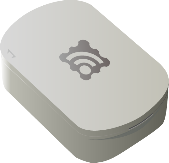
Appearance
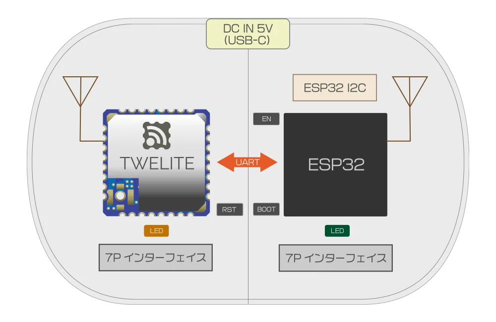
Internal Structure
For customers who frequently use the TWELITE series
Settings such as frequency channels are changed via the ESP32. Unlike other products, you cannot use the interactive mode from the 7P interface. Configuration is done using the TWELITE-specific Arduino library provided for ESP32.
Note: The 7P interface on the TWELITE side is only used for updating the SPOT-specific parent application.
By developing firmware for the ESP32, you can implement systems such as the following:
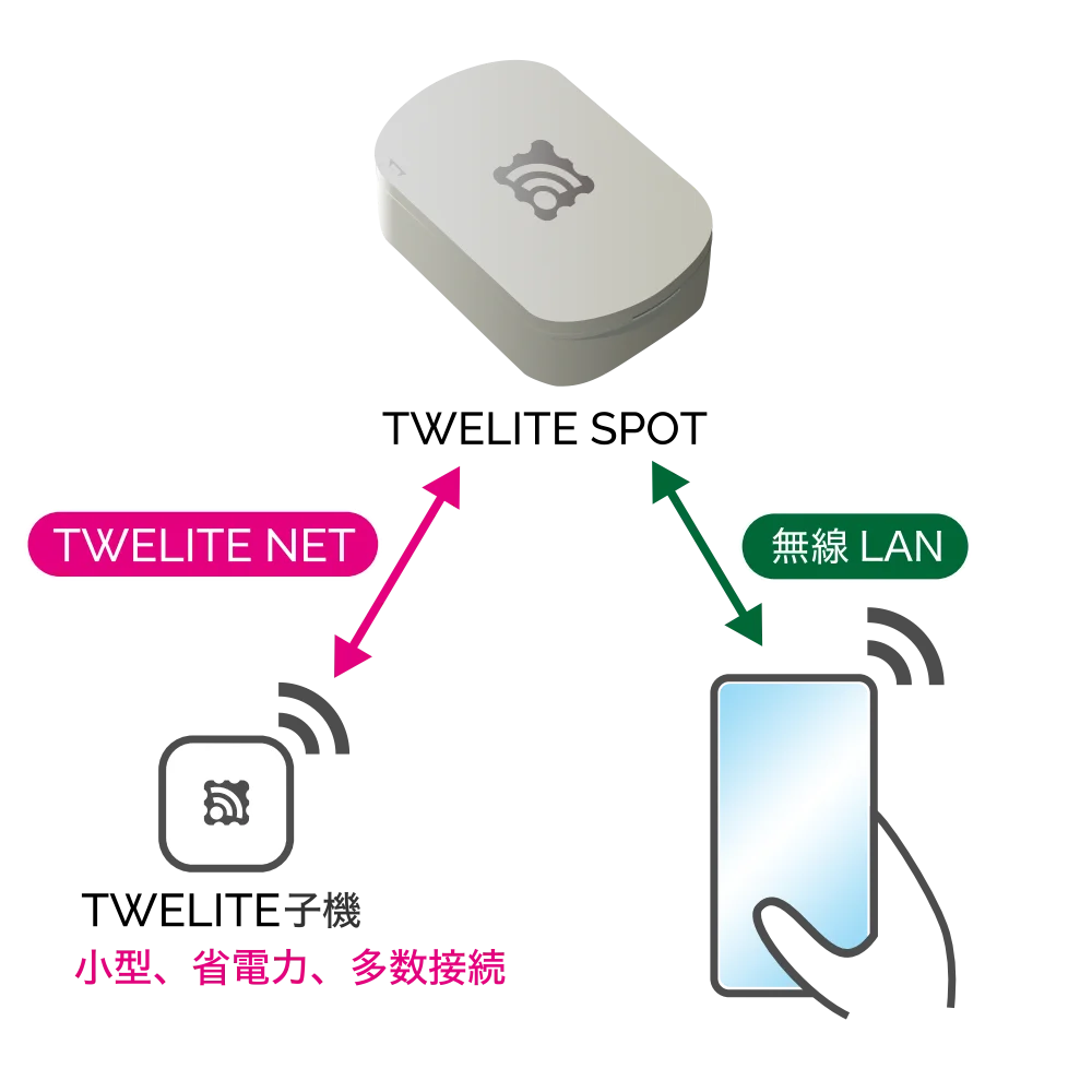 | 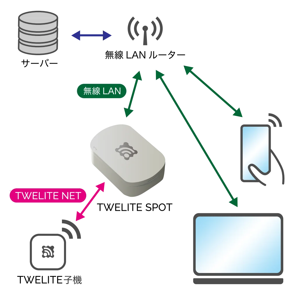 | 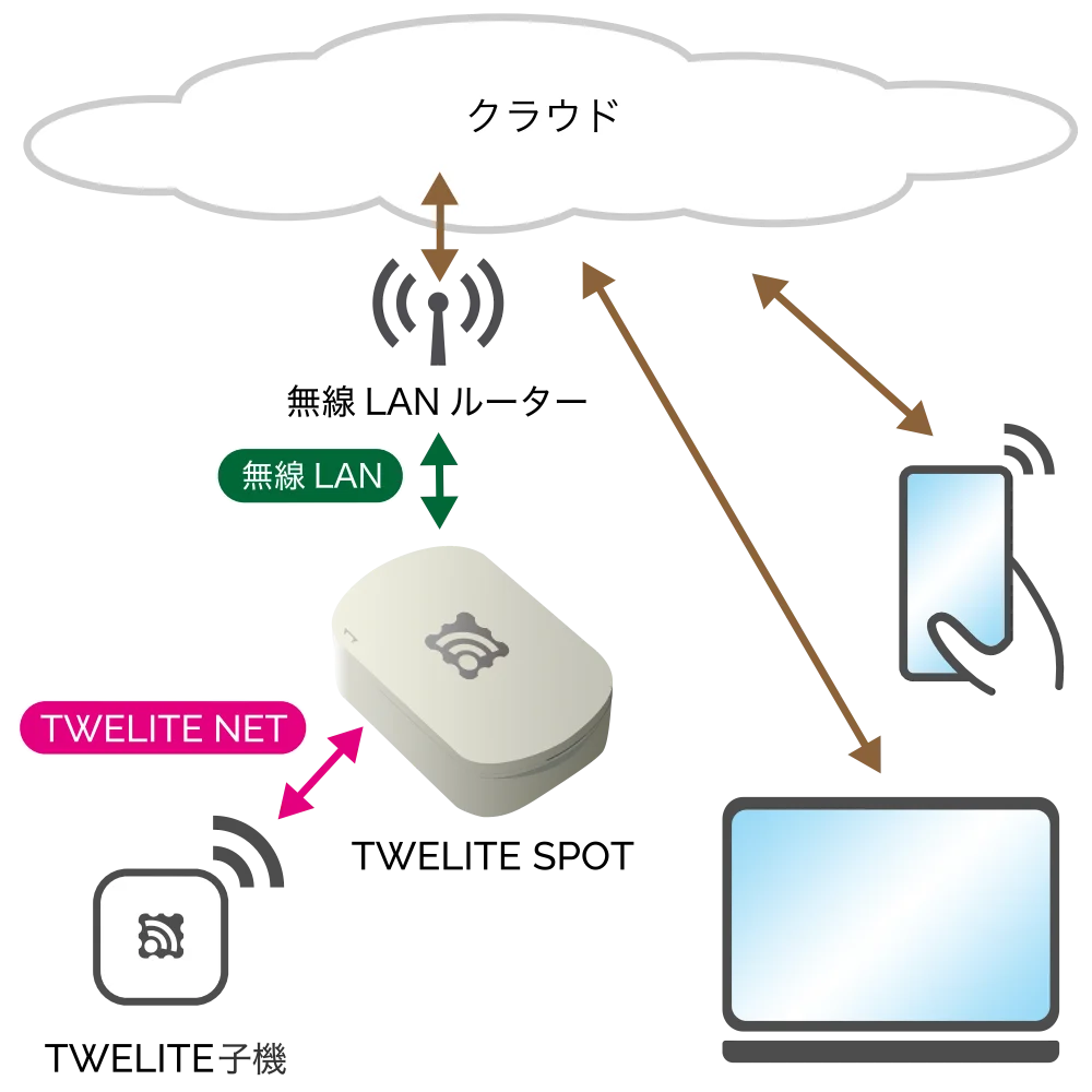 |
|---|---|---|
| Local Server | Local Gateway | IoT Gateway |
| Share data from TWELITE | Use data from TWELITE | Use data from TWELITE |
Local Server
The ESP32 is used as a server. For example, you can display acceleration data measured by a TWELITE CUE on a smartphone or operate the output ports of a TWELITE DIP from a smartphone.
Sample sketch
Local Gateway
The ESP32 connects to the LAN. For example, data sent from TWELITE ARIA devices installed throughout a building can be received by TWELITE SPOT devices on each floor, aggregating temperature and humidity data from all floors on a server within the LAN.
Sample sketch
IoT Gateway
The ESP32 connects to the Internet. For example, by attaching a TWELITE CUE and a magnet to a door, you can detect on the cloud whether the door remains open based on the acquired door open/close status.
Development with Arduino IDE and Dedicated Library
To build a system using TWELITE SPOT, you need to develop firmware for the ESP32.
Arduino IDE can be used for firmware development on the ESP32.
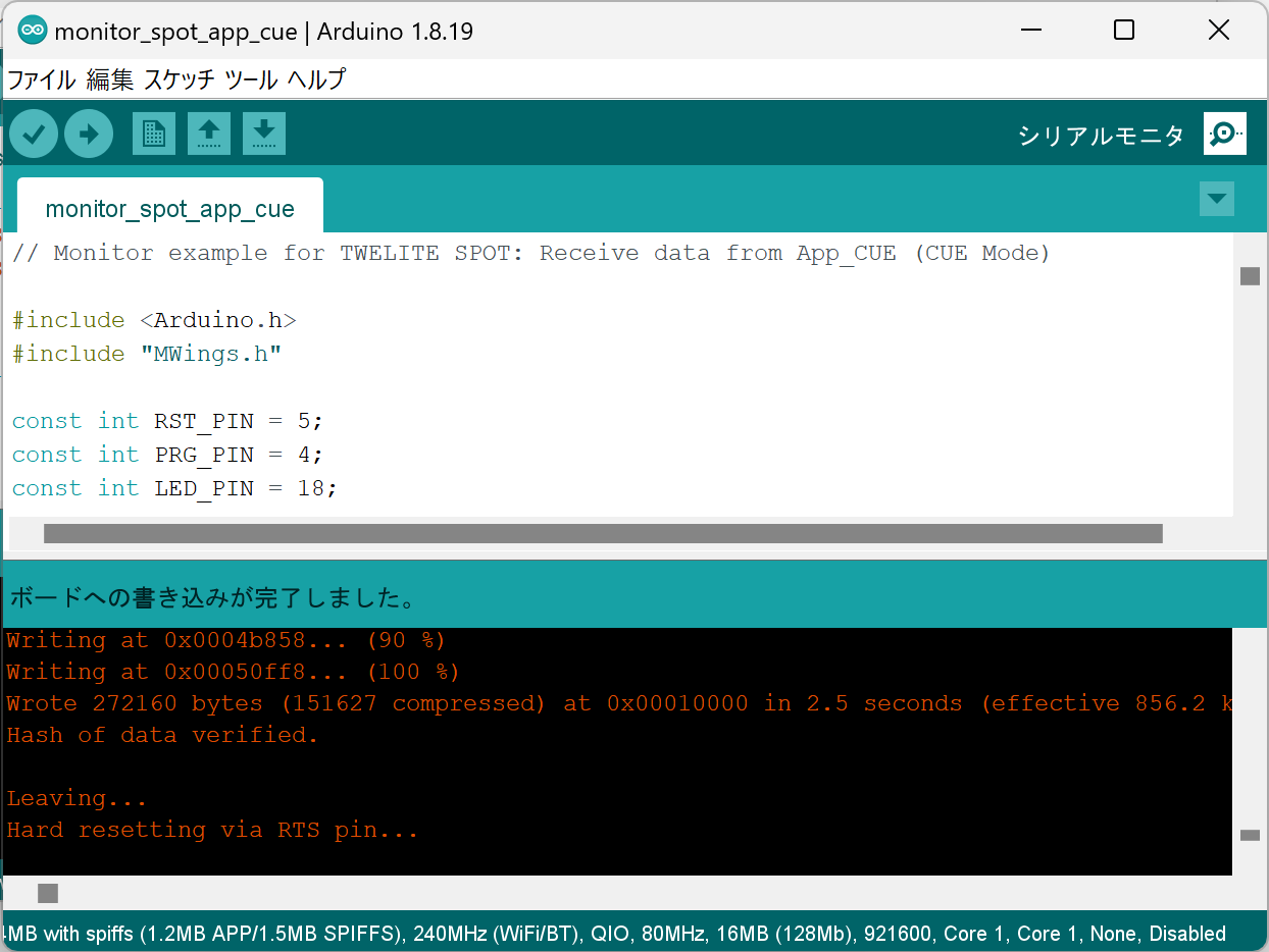
Development using Arduino IDE
There is a vast amount of information online about firmware development using Arduino IDE.
For example, try searching for esp32 arduino.
The MWings library, distributed via the Arduino Library Manager, makes it easy to receive packets from TWELITE Child devices and send commands to them.
The MWings library can also be used with the Arduino UNO R4 series.
Flow of the Start Guide
This start guide covers verifying TWELITE SPOT operation, setting up the ESP32 development environment, creating simple sketches, and writing them.
1. Verify TWELITE SPOT Operation
Contents
Using the pre-installed app on TWELITE SPOT, view acceleration sensor wireless tag TWELITE CUE data on a smartphone.
Required Items
| 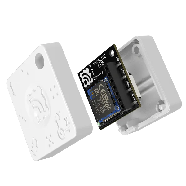 | |
|---|---|---|
| TWELITE SPOT | TWELITE CUE | |
| TWELITE Parent | TWELITE Child |
2. Perform Hello World on ESP32
Basics of Firmware Development Using ESP32
Contents
Set up the development environment, create and write a Hello World sketch, and verify operation.
Required Items
| 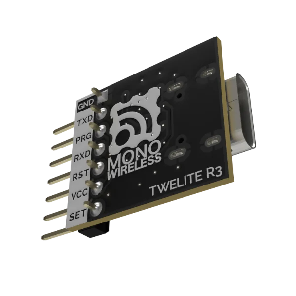 | |
|---|---|---|
| TWELITE SPOT | TWELITE R3 | |
| TWELITE SPOT device to write firmware | USB adapter to connect PC and TWELITE SPOT |
3. Acquire Data from TWELITE CUE
Contents
Output acceleration data from TWELITE CUE via ESP32.
Required Items
| | |
|---|---|---|
| TWELITE SPOT | TWELITE CUE | TWELITE R3 |
| TWELITE SPOT device to write firmware | TWELITE Child device to communicate with TWELITE SPOT | USB adapter to connect PC and TWELITE SPOT |
The start guide uses TWELITE CUE as the TWELITE Child device, but the content can also be applied to other TWELITE series such as the temperature and humidity sensor wireless tag TWELITE ARIA.
The start guide uses third-party open-source software.
We cannot provide detailed instructions on the use of third-party software. We also assume no responsibility for any damages resulting from the use of third-party software.
3.1 - Getting Started
Display acceleration data from TWELITE CUE on your smartphone using TWELITE SPOT
TWELITE SPOT can host dynamic pages on a web server running on ESP32, distributing data received from TWELITE Child devices within the network.
Using the pre-installed app on TWELITE SPOT, let’s view data from the Acceleration Sensor Wireless Tag TWELITE CUE on your smartphone.
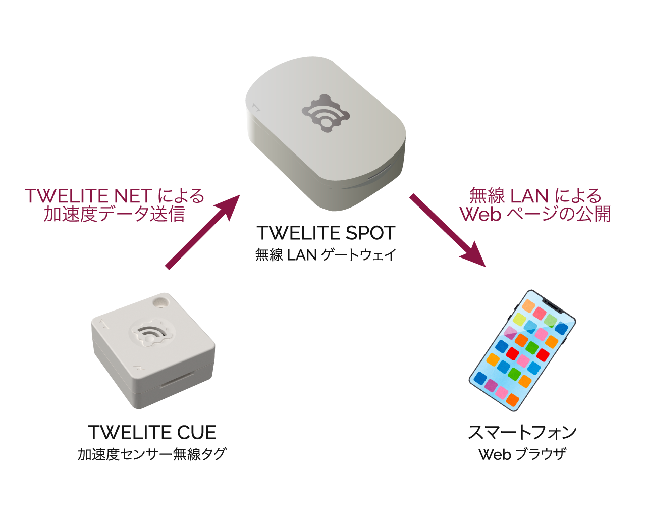
Operation Image
Here, TWELITE SPOT functions as a wireless LAN access point.
What You Need
-
Wireless LAN Gateway TWELITE SPOT
- USB-C cable for power
- USB AC adapter (capable of supplying 1A or more)
- Acceleration Sensor Wireless Tag TWELITE CUE (If you do not have one, please purchase it 👉 Retailers List)
- 📱 Smartphone
Confirm TWELITE SPOT Operation
1. Power On the Device ⚡
Connect the USB-C cable to the side of TWELITE SPOT and supply power from the USB AC adapter.
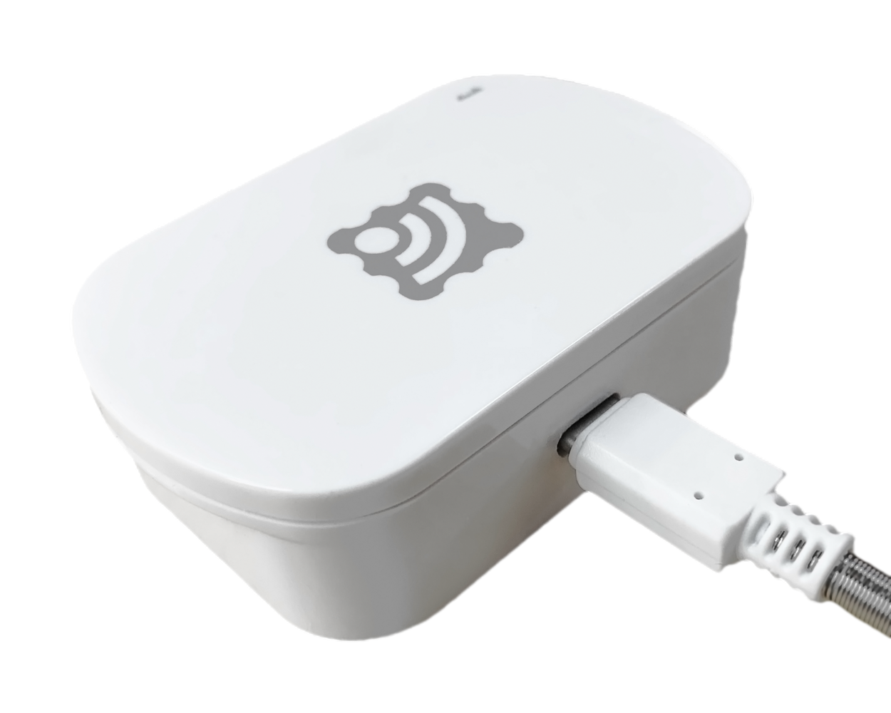
Connecting USB Power
2. Power On TWELITE CUE ⚡
Insert a CR2032 coin battery into TWELITE CUE. It will start operating immediately.
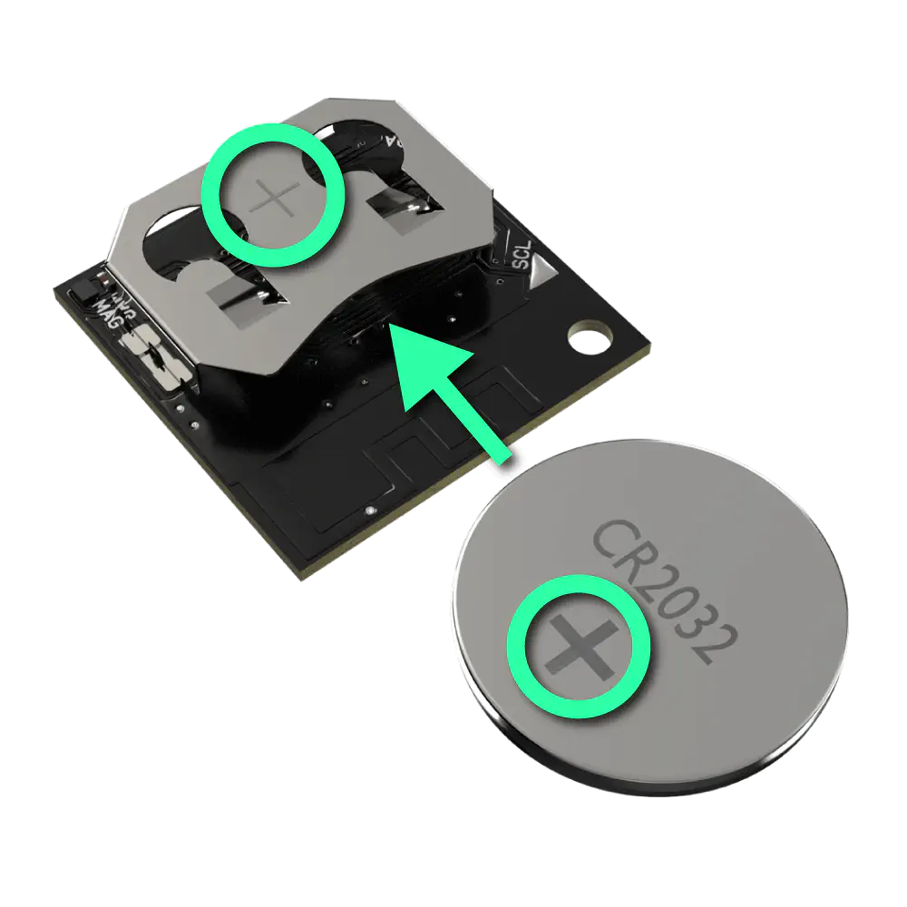
Inserting Coin Battery
When TWELITE CUE starts normally, the LED on the side with the logo will blink.
TWELITE CUE cannot communicate with TWELITE SPOT unless it is in the default factory settings.
If you have changed the settings of TWELITE CUE, please change the settings again to return it to factory default.
3. Connect Your Smartphone 📱
Connect your smartphone to the Wi-Fi network TWELITE SPOT (XXXX) from the Wi-Fi settings.
The password is
twelitespot. The XXXX in the SSID is a device-specific identifier.4. Open a Web Browser 🌐
Open a web browser on your smartphone and access spot.local.
If you cannot connect, try accessing 192.168.1.1.
If that still does not work, try accessing http://192.168.1.1/.
You will see a screen like the following.
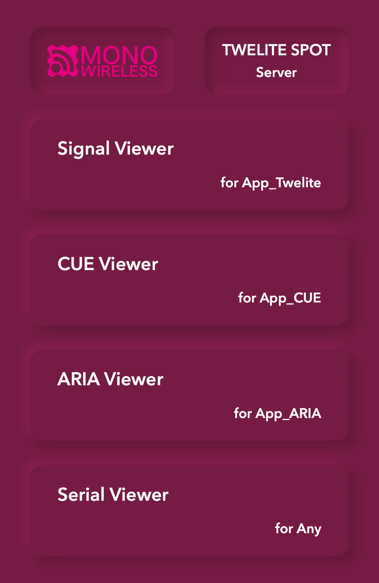
Top Page
5. Open the CUE Viewer 📈
Tap on CUE Viewer to open the CUE viewer screen.
You will see a screen like the following.
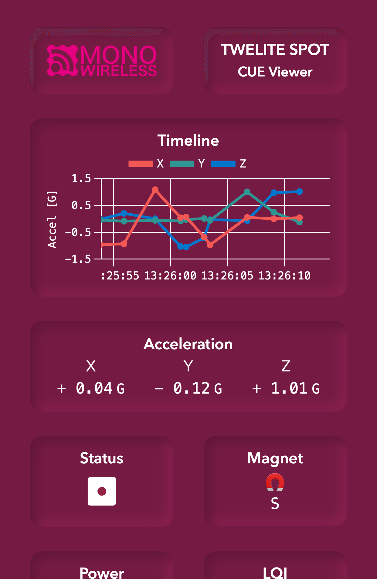
Try changing the orientation of TWELITE CUE.
The CUE viewer displays the number on the dice printed on TWELITE CUE.
You have confirmed the operation of TWELITE SPOT using TWELITE NET and wireless LAN!
For more details about the features, please refer to the TWELITE SPOT Manual.
3.2 - Basics of Firmware Development with ESP32
Try Hello World on ESP32 for TWELITE SPOT firmware development
ESP32 can build a system using wireless LAN on its own. For example, you can display data on a hosted web page, send data to a server within the LAN via WebSocket, or send REST API requests to cloud services.
TWELITE SPOT is a product that combines this ESP32 with TWELITE, enabling the use of many small, low-power wireless tags.
First, let’s try Hello World to learn the basics of firmware development for ESP32.
We will set up the development environment, create and write the Hello World sketch, and verify its operation.
This content also serves as an operation check for TWELITE SPOT. Even if you have experience developing firmware for ESP32 using Arduino IDE, please review the following.
TWELITE SPOT is equipped with both TWELITE and ESP32, but usually, you only develop firmware for the latter. For TWELITE firmware, please use the pre-installed Parent and Repeater applications.
What You Need
-
Wireless LAN Gateway TWELITE SPOT
- USB-C cable for power
- USB AC adapter (capable of supplying 1A or more)
-
USB Adapter TWELITE R3 (Please purchase if you do not have one 👉 List of retailers)
- USB-C cable for communication
- 💻 Computer
Setting Up the Environment
1. Install the IDE 🚛
If you have not installed Arduino IDE on your computer, please download and install it from the Arduino official download page (IDE 1.x or 2.x).
For detailed instructions, please refer to the TWELITE SPOT manual (IDE 1.x) or TWELITE SPOT manual (IDE 2.x).
Please install Arduino IDE 1.x.
Although the latest Arduino IDE 2.x can also write sketches similarly to Arduino IDE 1.x, as of May 2023, the Java-based plugin does not work, so the Legacy IDE is recommended.
2. Install the Toolchain 🚚
If you have not installed Arduino core for the ESP32 in Arduino IDE, add the following URL to the Board Manager URLs and install the esp32 board definition.
https://espressif.github.io/arduino-esp32/package_esp32_index.json
For detailed instructions, please refer to the TWELITE SPOT manual (IDE 1.x) or TWELITE SPOT manual (IDE 2.x).
3. Configure the Board Settings ⚙️
From here, the content is specific to TWELITE SPOT.
Configure Arduino core for the ESP32 to match TWELITE SPOT.
Select the Board Type
From the toolbar, select Tools -> Board -> ESP32 Arduino -> ESP32 Dev Module.
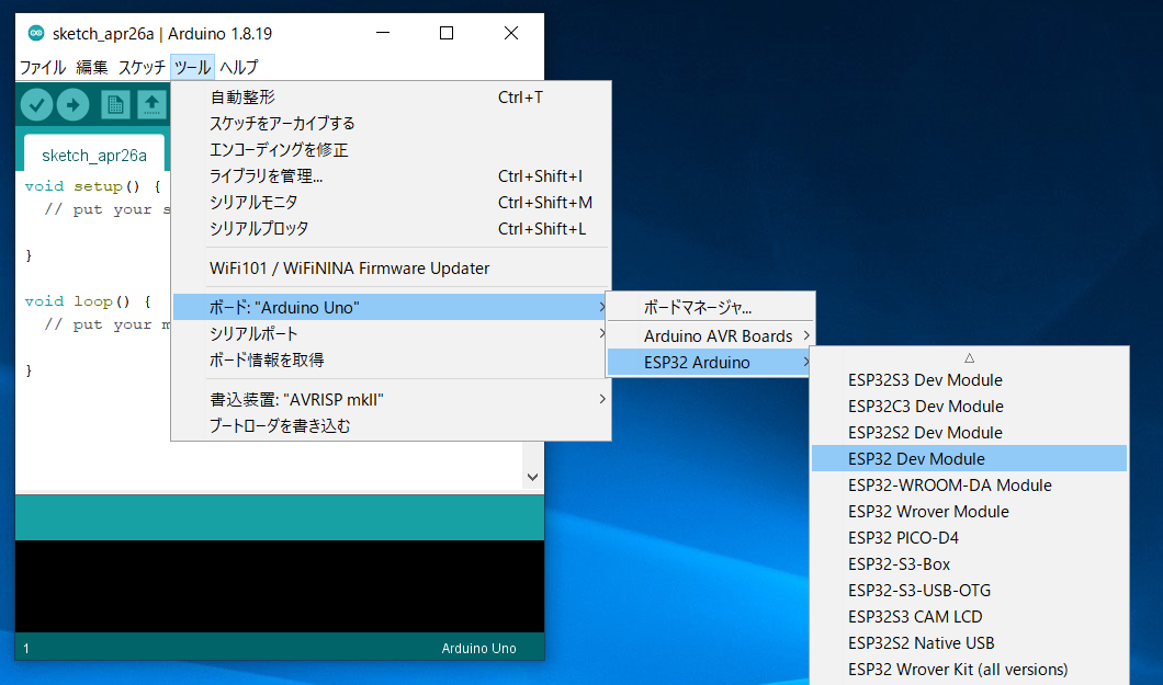
Location of ESP32 Dev Module
Configure Board Settings
Configure as shown in the figure below.
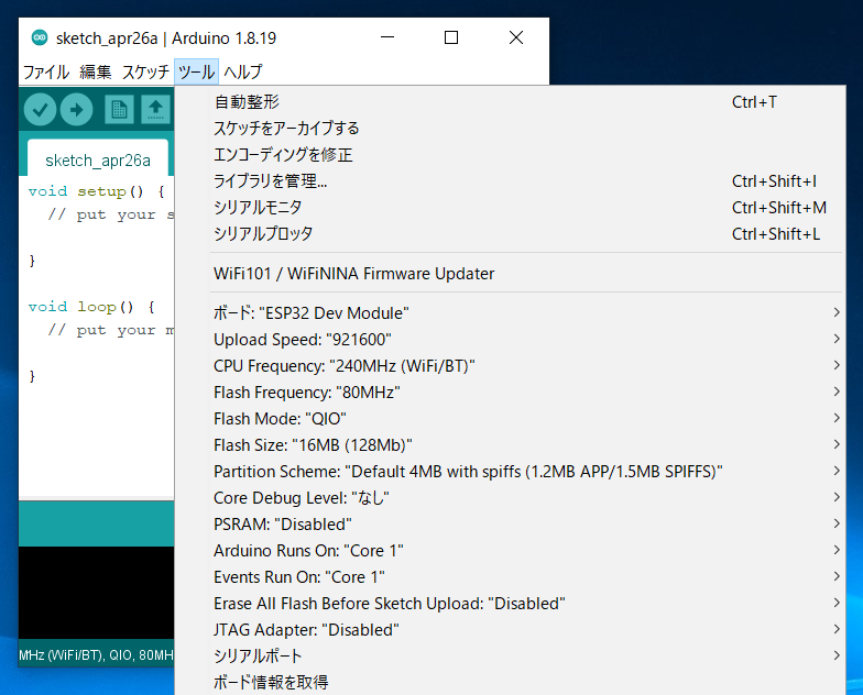
Settings after configuration
Change
Flash size from 4MB (32Mb) to 16MB (128Mb).Prepare TWELITE SPOT
1. Remove the Cover ⛏️
Remove the cover on the top of the TWELITE SPOT case.
Switches and connectors will be exposed.
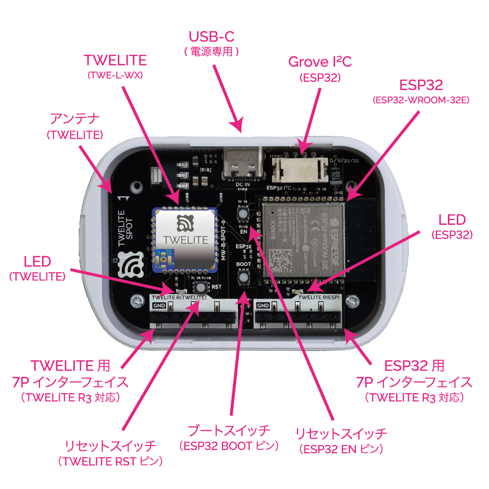
Names of each part
For details of each part, please see the datasheet.
2. Connect TWELITE R3 / R2 🔌
Connect TWELITE R3 / R2 to the 7P interface for ESP32 (marked ESP32).
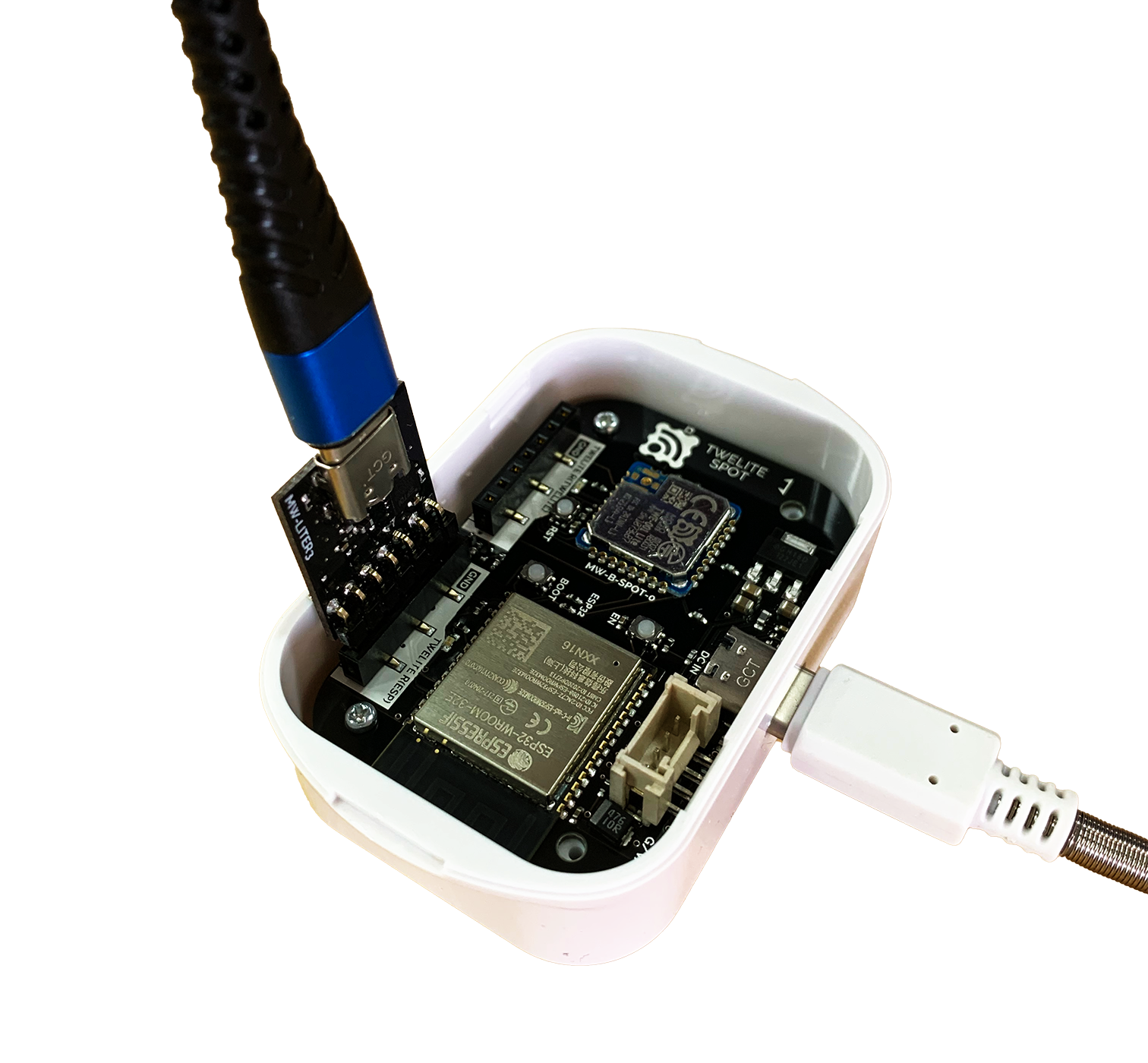
Connection example (ESP32)
Always connect TWELITE R3 / R2 to TWELITE SPOT in the same orientation as shown above. Connecting in the wrong orientation may damage TWELITE SPOT or TWELITE R3 / R2.
Tip 👉 Face the surface of TWELITE R3 / R2 towards the connection target.
The VCC pin of each 7P interface is not connected. Since TWELITE R series cannot supply power, you need to supply power from the USB-C connector on the side.
3. Connect USB-C Power ⚡
Supply 5V power to the USB-C connector on the side.
Run the Sketch
In Arduino, programs/projects are called sketches.
1. Create the Sketch 👨💻
Create a Hello World sketch that outputs a string from ESP32 to the serial port and displays it on the Arduino IDE serial monitor.
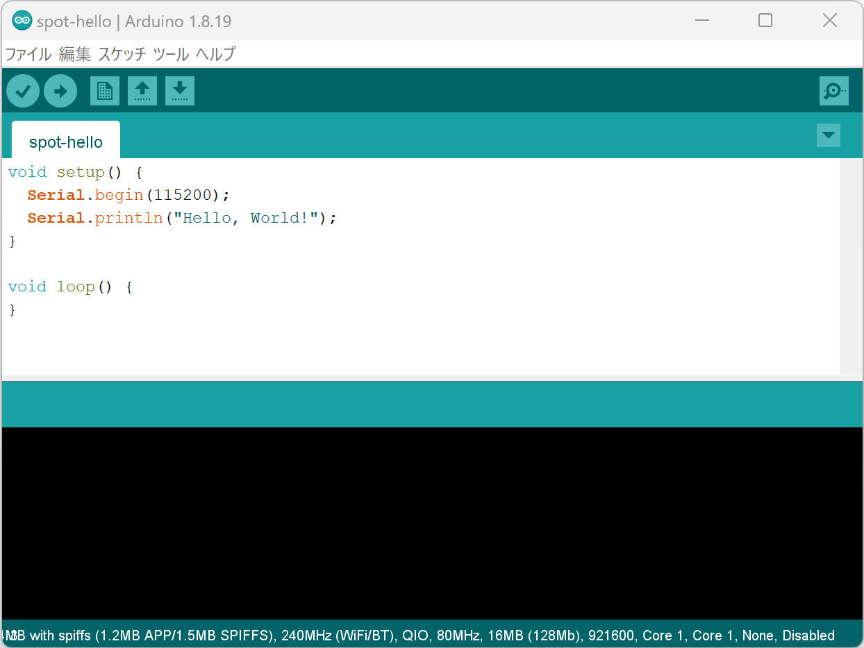
Sketch creation screen
Start Arduino IDE and enter the following code.
void setup() {
  Serial.begin(115200);
  Serial.println("Hello, World!");
}

void loop() {
}
The contents of setup() run only once at startup. The contents of loop() run repeatedly without end.
On the second line, the baud rate (communication speed) of the serial port is set to 115200bps.
Serial.begin(115200);
This baud rate must match the baud rate of the serial monitor described later.
On the third line, the string "Hello, World!" is output to the serial port.
Serial.println("Hello, World!");
Serial.println() automatically appends a newline (CRLF) at the end.2. Write the Sketch ⚒️
Select the Serial Port
From the Tools -> Serial Port menu, select the port for the connected device (TWELITE R series).
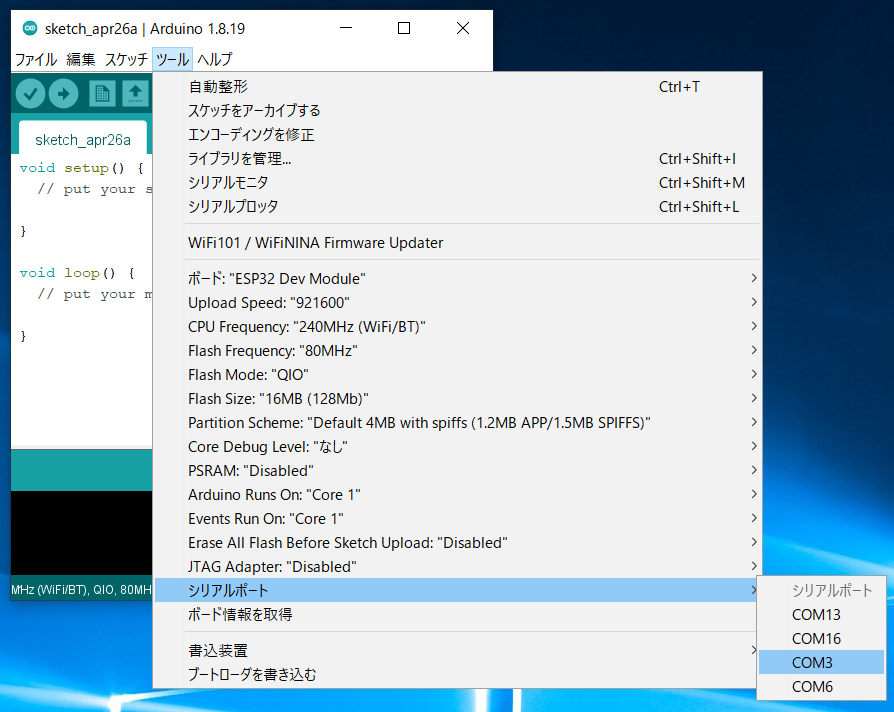
Serial port selection
On Windows, serial ports are named like
COM?, and on macOS/Linux, like /dev/tty?.Start ESP32
Start ESP32 in programming mode.
Press the ESP32 reset switch EN(RST) and the ESP32 boot switch BOOT, then release them in the order EN(RST) -> BOOT.
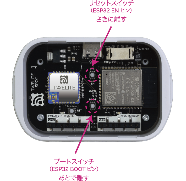
Button locations
It is important to reset while holding down
BOOT.Write the Sketch
Click the Upload button on the Arduino IDE toolbar.
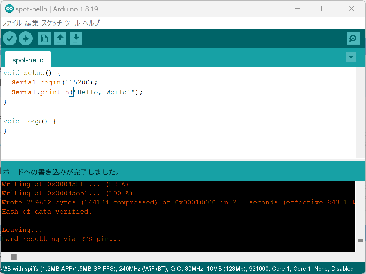
Upload completion screen
For details on how to write, please refer to the TWELITE SPOT manual.
3. Open the Serial Monitor 🖥️
Open the Screen
Click the Serial Monitor button at the top right of Arduino IDE.
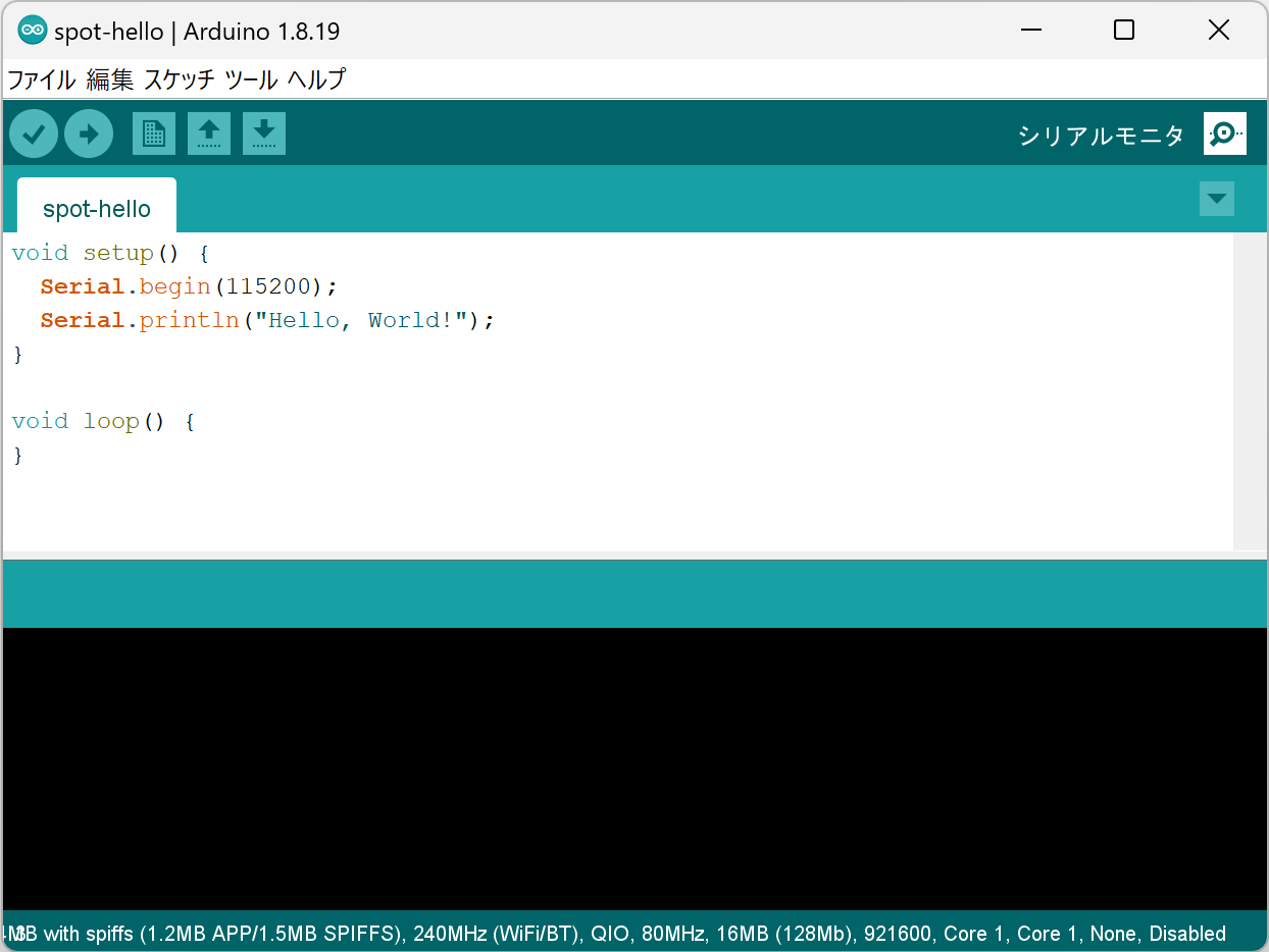
Serial monitor button at top right
Configure Settings
Set the baud rate at the bottom right of the serial monitor screen to 115200.
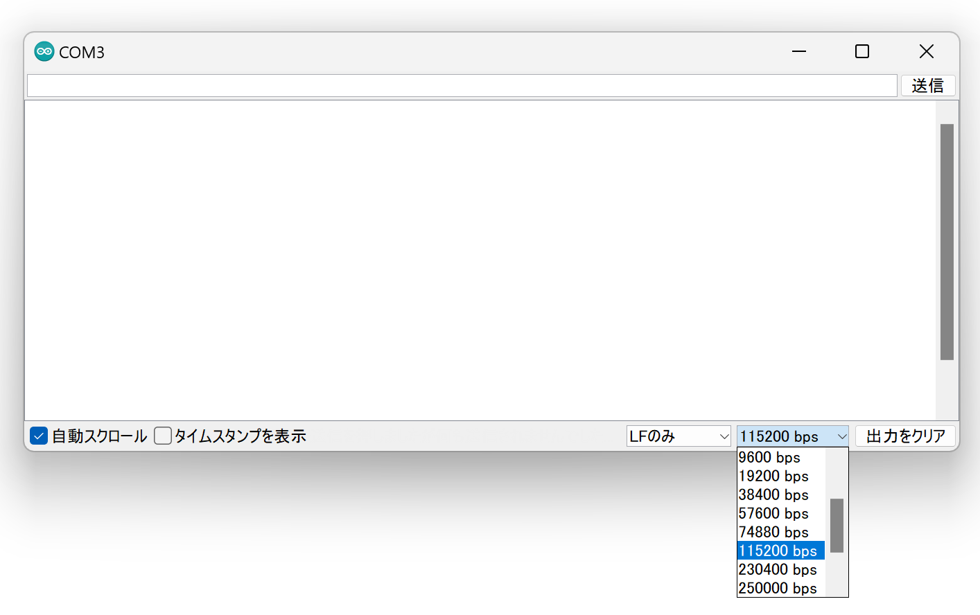
Baud rate setting
4. Run the Sketch 🚀
Restart ESP32
After writing is complete, press and release the ESP32 reset switch EN(RST) on TWELITE SPOT to reset ESP32.
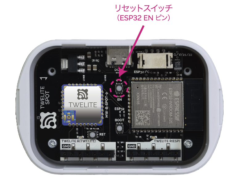
Reset switch location
Check the Serial Monitor
If the following string is displayed on the serial monitor, it was successful.
Hello, World!
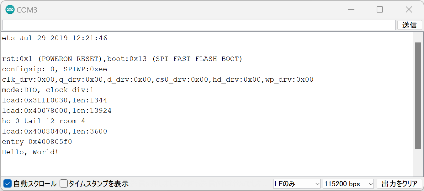
Successful Hello World output
The firmware development environment for ESP32 mounted on TWELITE SPOT is ready!
3.3 - Receiving Data from a TWELITE Child
Output acceleration data received from TWELITE CUE to the serial monitor
TWELITE SPOT enables the use of numerous small, low-power wireless tags by combining ESP32 with TWELITE.
Let’s start by outputting acceleration data from the TWELITE CUE via ESP32.
What You Need
-
Wireless LAN Gateway TWELITE SPOT
- USB-C cable for power
- USB AC adapter (capable of supplying 1A or more)
-
Acceleration Sensor Wireless Tag TWELITE CUE (If you do not have one, please purchase 👉 List of Retailers)
- CR2032 coin battery
-
USB Adapter TWELITE R3 (If you do not have one, please purchase 👉 List of Retailers)
- USB-C cable for communication
- 💻 Computer
In this article, we use TWELITE CUE as the TWELITE Child, but the content can also be applied to devices such as the Temperature and Humidity Sensor Wireless Tag TWELITE ARIA.
Setting Up the Environment
1. Install the Development Environment 🚛
If you have not set up the environment described in Basic Firmware Development Using ESP32, please do so first.
2. Configure the Board Settings ⚙️
Set the board type to ESP32 Dev Module and configure as shown below.
Settings After Configuration
3. Install the Library 🚚
Install the MWings Library required to use TWELITE from ESP32.
The MWings library simplifies communication with all TWELITE series products such as TWELITE CUE / TWELITE ARIA, TWELITE PAL, TWELITE DIP, and TWELITE UART.
Open Sketch -> Include Library -> Manage Libraries…
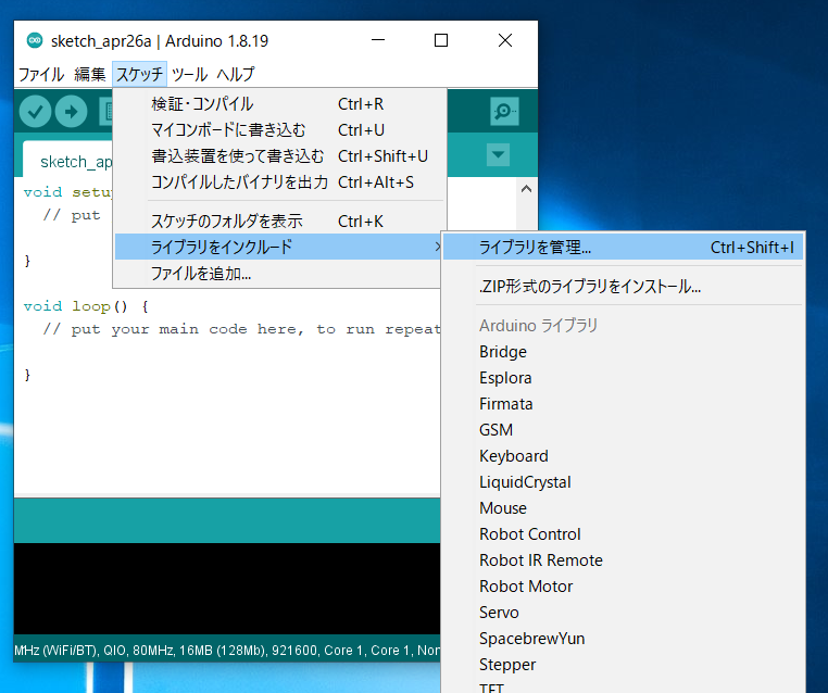
Location of Library Manager
Type MWings in the search box and install MWings.
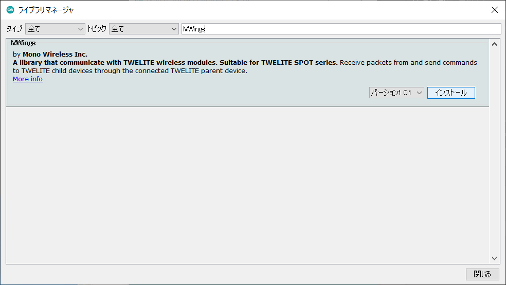
Library Manager
MWings library can also be used with Arduino UNO R4 series.
Prepare the TWELITE SPOT
1. Remove the Cover ⛏️
Remove the top cover of the TWELITE SPOT case.
2. Connect the Cables 🔌
Connect TWELITE R3 / R2 to the ESP32 7P interface labeled ESP32, then supply 5V power to the USB-C connector on the side.
Connection Example (ESP32)
Run the Sketch First
1. Open the Sample 📂
Launch Arduino IDE, then select File -> Examples -> MWings -> monitor_spot_app_cue.
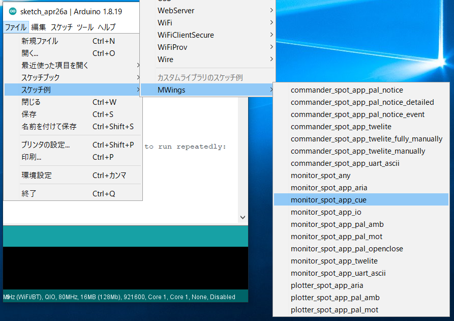
For TWELITE ARIA, select monitor_spot_app_aria.
2. Select the Serial Port ⚙️
From the Tools -> Port menu, select the port of the connected device (TWELITE R series).
Serial Port Selection
3. Start the ESP32 👇
Start ESP32 in programming mode.
Press the reset switch EN(RST) and the ESP32 boot switch BOOT, then release in the order EN(RST) -> BOOT.
Button Locations
4. Write the Sketch ⚒️
Click the Upload button at the top of the Arduino IDE.
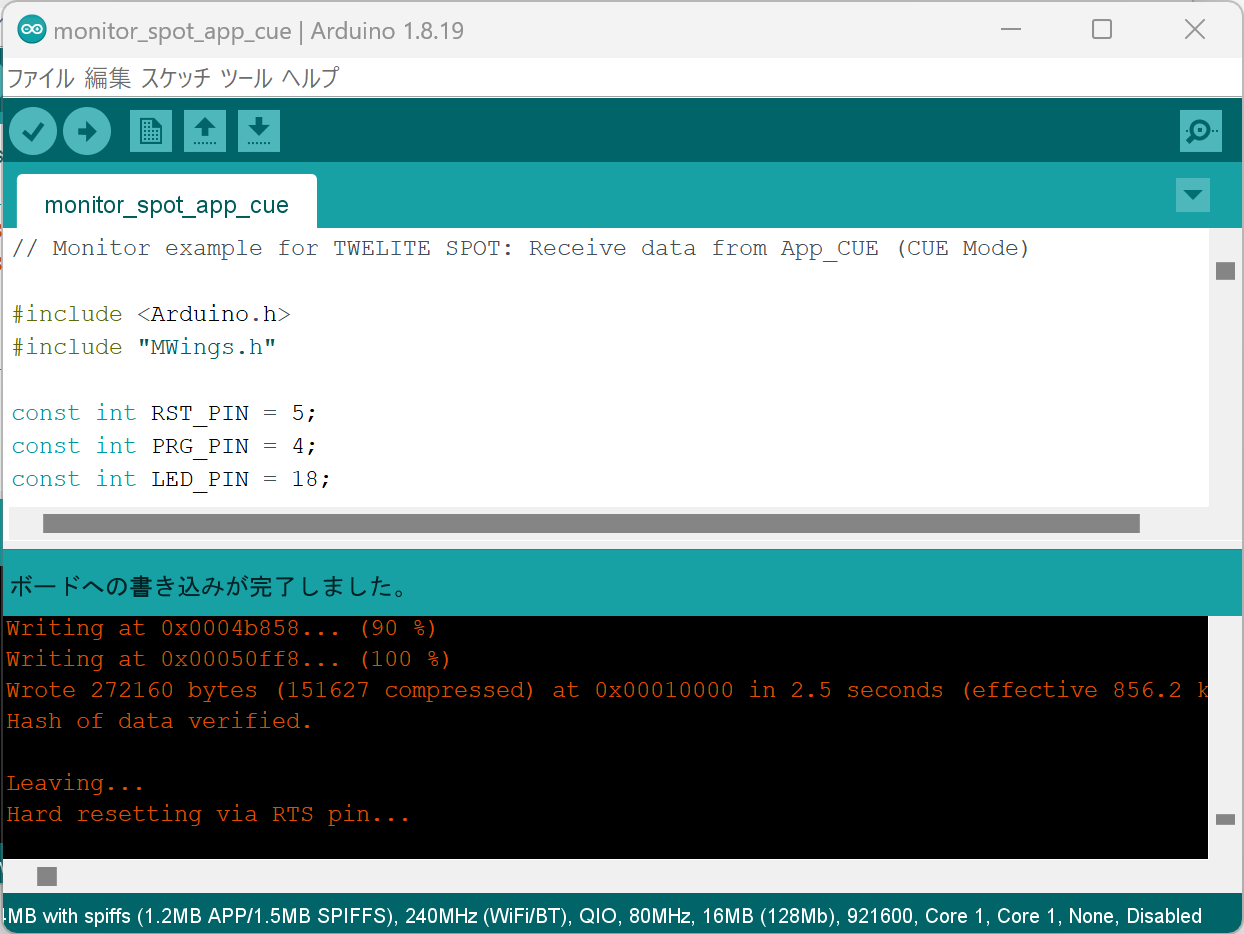
Upload Completion Screen
For detailed writing instructions, please see the TWELITE SPOT Manual.
5. Open the Serial Monitor 🖥️
Open the Window
Click the Serial Monitor button at the top right of the Arduino IDE.
Serial Monitor Button at Top Right
Configure
Set the serial monitor baud rate to 115200.
6. Restart ESP32 🚀
After writing is complete, press and release the ESP32 reset switch EN(RST) on the TWELITE SPOT to reset the ESP32.
Reset Switch Location
Restarting ESP32 also restarts TWELITE.
- When ESP32 starts, the LED on the ESP32 side of the board blinks.
- When TWELITE starts, the LED on the TWELITE side of the board lights for 1 second.
7. Confirm Startup 💬
If the following string appears on the serial monitor, startup was successful.
Monitor example for TWELITE SPOT: App_CUE (CUE Mode)
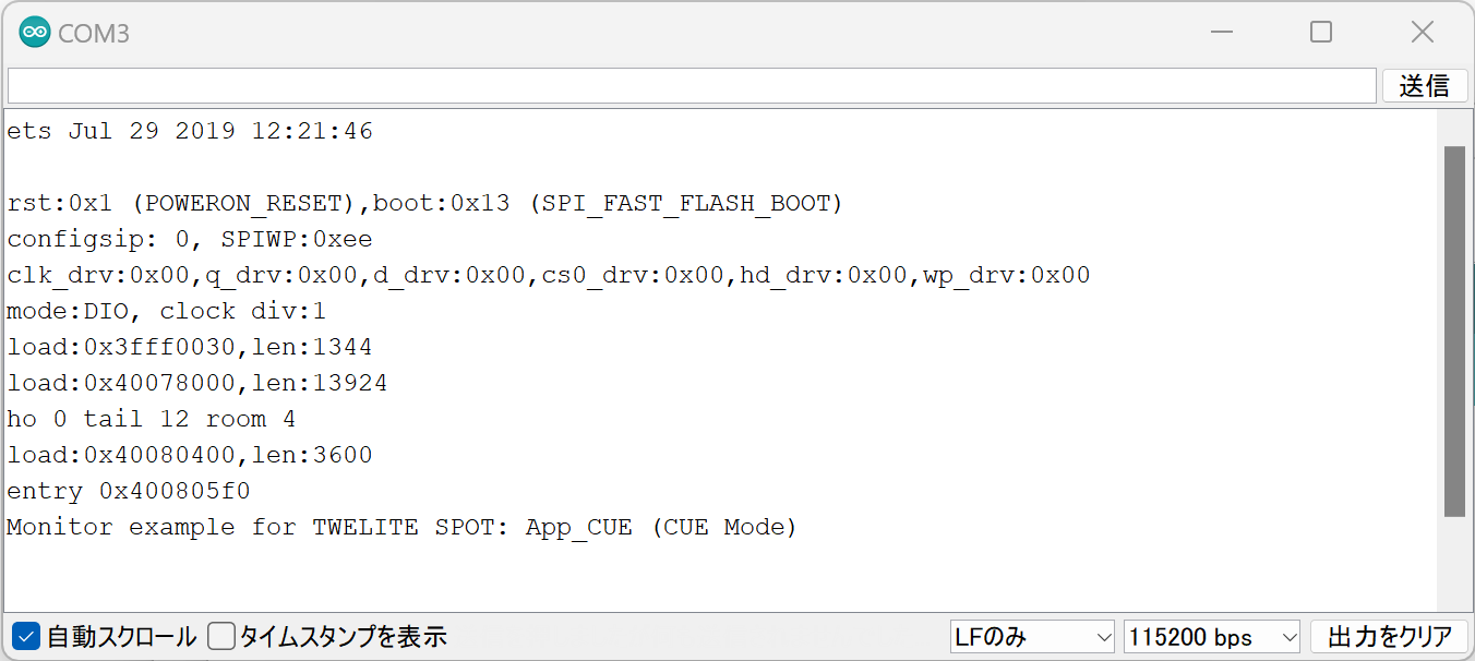
Successful Startup Display
For TWELITE ARIA, the display will look like this:
Monitor example for TWELITE SPOT: App_ARIA (ARIA Mode)
8. Start TWELITE CUE ⚡
Insert a CR2032 coin battery into the TWELITE CUE. It will start operating immediately.
Inserting the Coin Battery
When TWELITE CUE starts normally, the LED on the logo side will blink.
If you have changed TWELITE CUE settings, please change the settings again and restore factory defaults (TWELITE CUE mode, Application ID
0x67720102, Frequency Channel 18).9. Confirm Reception 💬
If the following string appears on the serial monitor, data reception from TWELITE CUE was successful.
Packet Number:     #3
Source Logical ID: 0x1
LQI:               147
Supply Voltage:    3310 mV
Accel Event:       Dice (1)
Accel X Axis [0]:  72 mG
Accel Y Axis [0]:  -64 mG
Accel Z Axis [0]:  1000 mG
Magnet State:      Leaving or Not found
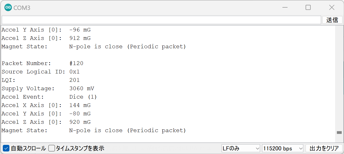
Successful Reception Display
For TWELITE ARIA, temperature and humidity data is output instead of acceleration data, so some parts of the display differ.
You have successfully read acceleration data from TWELITE CUE via the TWELITE installed on TWELITE SPOT!
Sketch Explanation
Here is a brief explanation of the sample sketch (monitor_spot_app_cue.ino).
Including the Library
Line 4 includes the MWings library you installed earlier.
#include "MWings.h"
Defining Pin Numbers
Lines 6-8 define the pin numbers.
const int RST_PIN = 5;
const int PRG_PIN = 4;
const int LED_PIN = 18;
| Name | Description |
|---|---|
RST_PIN | Pin number connected to the TWELITE RST pin |
PRG_PIN | Pin number connected to the TWELITE PRG pin |
LED_PIN | Pin number connected to the ESP32 LED on the board |
Do not change the RST_PIN and PRG_PIN numbers.
Changing these will prevent proper TWELITE startup.
For connection details, see the Circuit Diagram in the TWELITE SPOT Datasheet.
Defining TWELITE Settings
Lines 10-11 define the settings applied to the TWELITE Parent installed in TWELITE SPOT.
const uint8_t TWE_CHANNEL = 18;
const uint32_t TWE_APP_ID = 0x67720102;
| Name | Description |
|---|---|
TWE_CHANNEL | TWELITE frequency channel |
TWE_APP_ID | TWELITE application ID |
Serial Port Setup
Lines 19-21 initialize the serial ports and output the startup message to the serial monitor.
  Serial.begin(115200);
  Serial.println("Monitor example for TWELITE SPOT: App_CUE (CUE Mode)");
  Serial2.begin(115200);
Serial is used for communication with the Arduino IDE serial monitor. The baud rate is set to 115200 bps to match the serial monitor settings.
Serial2 is used for communication with the TWELITE Parent installed on TWELITE SPOT. This is also set to 115200 bps to match the Parent’s initial settings.
The TWELITE Parent’s serial communication initial settings are 115200 bps / 8N1.
TWELITE Initialization
Lines 24-26 call Twelite.begin() to configure and start the TWELITE Parent on TWELITE SPOT.
    Twelite.begin(Serial2,
                      LED_PIN, RST_PIN, PRG_PIN,
                      TWE_CHANNEL, TWE_APP_ID);
| Parameter | Type | Description |
|---|---|---|
Serial2 | HardwareSerial& | Serial port used for communication with TWELITE |
LED_PIN | int | Pin number connected to the status LED |
RST_PIN | int | Pin number connected to the TWELITE RST pin |
PRG_PIN | int | Pin number connected to the TWELITE PRG pin |
TWE_CHANNEL | uint8_t | TWELITE frequency channel |
TWE_APP_ID | uint32_t | TWELITE application ID |
Registering Packet Reception Event
Lines 29-49 call Twelite.on() to register the processing to be done when data is received from the TWELITE CUE.
Here, the received packet content is output to the serial monitor.
    Twelite.on([](const ParsedAppCuePacket& packet) {
        Serial.println("");
        Serial.print("Packet Number:     #");
        Serial.println(packet.u16SequenceNumber, DEC);
        Serial.print("Source Logical ID: 0x");
        Serial.println(packet.u8SourceLogicalId, HEX);
        Serial.print("LQI:               ");
        Serial.println(packet.u8Lqi, DEC);
        Serial.print("Supply Voltage:    ");
        Serial.print(packet.u16SupplyVoltage, DEC); Serial.println(" mV");
        Serial.print("Accel Event:       ");
        printAccelEvent(packet.u8AccelEvent);
        Serial.print("Accel X Axis [0]:  ");
        Serial.print(packet.i16SamplesX[0], DEC); Serial.println(" mG");
        Serial.print("Accel Y Axis [0]:  ");
        Serial.print(packet.i16SamplesY[0], DEC); Serial.println(" mG");
        Serial.print("Accel Z Axis [0]:  ");
        Serial.print(packet.i16SamplesZ[0], DEC); Serial.println(" mG");
        Serial.print("Magnet State:      ");
        printMagnetState(packet.u8MagnetState, packet.bMagnetStateChanged);
    });
This event is called only when a packet is received from the TWELITE CUE.
The received packet content is stored in the argument packet of type ParsedAppCuePacket.
packet contains the following data (the bold data are used in the code above).
| Data | Type | Description |
|---|---|---|
packet.u32SourceSerialId | uint32_t | Source Serial ID |
packet.u8SourceLogicalId | uint8_t | Source Logical Device ID |
packet.u16SequenceNumber | uint16_t | Sequence Number |
packet.u8Lqi | uint8_t | LQI (Radio Signal Quality Indicator) |
packet.u16SupplyVoltage | uint16_t | Supply Voltage (mV) |
packet.i16SamplesX | int16_t[10] | X-axis acceleration samples (mG) |
packet.i16SamplesY | int16_t[10] | Y-axis acceleration samples (mG) |
packet.i16SamplesZ | int16_t[10] | Z-axis acceleration samples (mG) |
packet.u8SampleCount | uint8_t | Number of samples |
packet.bHasAccelEvent | bool | true if acceleration event is present |
packet.u8AccelEvent | uint8_t | Acceleration Event ID |
packet.u8MagnetState | uint8_t | Magnetic Event ID |
packet.bMagnetStateChanged | bool | true if magnetic sensor state changed |
For TWELITE ARIA, use the ParsedAppAriaPacket type.
Twelite.on() can be written for each data type, for example, you can add the following to handle data received from TWELITE ARIA.
Twelite.on([](const ParsedAppAriaPacket& packet) {
    // Handle packet...
});
For details, see the API Reference.
Updating TWELITE Data
Line 55 calls Twelite.update().
Twelite.update();
Twelite.update() reads packet data (ModBus ASCII format) from the TWELITE Parent one byte at a time.
By repeatedly calling
Twelite.update() inside loop(), the parsing of packet data from the TWELITE Parent progresses. When packet parsing is complete, events like those described above are called.Blocking calls such as
delay() may cause packet data reading to fall behind. Always implement time-consuming processes asynchronously and keep the loop() function running as fast as possible.You have learned how to read acceleration data from TWELITE CUE via TWELITE installed on TWELITE SPOT!
For further steps, see the sketch explanation below and Related Information.
3.4 - Related Information
For further study
This page summarizes materials useful for firmware development of TWELITE SPOT.
MWings Library
- GitHub Repository: monowireless/mwings_arduino
- MWings API Reference: TWELITE Wings API for 32-bit Arduinos
TWELITE Product Datasheets
TWELITE SPOT Manuals
Sketch Explanations
Others
- Installation Methods Considering Wireless Performance
- Setting Up Development Environment with Arduino IDE 1.x
- Setting Up Development Environment with Arduino IDE 2.x
- How to Write Sketches to ESP32
- How to Write Files to ESP32 (Arduino IDE 1.x)
- How to Write Files to ESP32 (Arduino IDE 2.x)
- How to Write with Specified Partition Table on ESP32
External Links
Arduino
- Official Site: Arduino - Home
- API Reference: Arduino Reference - Arduino Reference
- Coding Style Guide: Arduino Style Guide for Creating Libraries | Arduino Documentation
- Official JSON Library: arduino-libraries/Arduino_JSON: Official JSON Library for Arduino
- Official NTP Library: arduino-libraries/NTPClient: Connect to a NTP server
ESP32
- Product Information: ESP32 Wi-Fi & Bluetooth MCU I Espressif Systems
- Datasheet: esp32_datasheet_en.pdf
- Arduino Toolchain: espressif/arduino-esp32: Arduino core for the ESP32
- Getting Started Guide: Getting Started — Arduino-ESP32 documentation
- Installation Guide: Installing — Arduino-ESP32 documentation
- API Reference: Libraries — Arduino-ESP32 documentation
- Wi-Fi API: Wi-Fi API — Arduino-ESP32 documentation
- Tutorials: Tutorials — Arduino-ESP32 documentation
- Troubleshooting: Troubleshooting — Arduino-ESP32 documentation
- ESP-IDF: espressif/esp-idf: Espressif IoT Development Framework
- Documentation: ESP-IDF Programming Guide - ESP32
- Multitasking and Queue Related: FreeRTOS (ESP-IDF) - ESP32
- Documentation: ESP-IDF Programming Guide - ESP32
ESP-IDF is the official development environment for ESP32 using FreeRTOS.
Arduino core for the ESP32 is implemented based on ESP-IDF, so you can also call ESP-IDF functions from Arduino.
The sketch spot-google-sheets utilizes FreeRTOS multitasking and queues.
For example, to perform multitasking, functions like
xTaskCreatePinnedToCore()can be used.
Community
Libraries
- Asynchronous TCP:
me-no-dev/AsyncTCP: Async TCP Library for ESP32ESP32Async/AsyncTCP: Async TCP Library for ESP32 - Asynchronous Web Server:
me-no-dev/ESPAsyncWebServer: Async Web Server for ESP8266 and ESP32ESP32Async/ESPAsyncWebServer: Async Web Server for ESP32 - WebSocket: Links2004/arduinoWebSockets: arduinoWebSockets
- Google Spreadsheets: mobizt/ESP-Google-Sheet-Client: Arduino Google Sheet REST client library
- Date and Time: PaulStoffregen/Time: Time library for Arduino
- Seeed 96x96 / 128x128 OLED: Seeed-Studio/OLED_Display_96X96: Seeed OLED Display 96*96 library
Plugins
- File Writing IDE 1.x: me-no-dev/arduino-esp32fs-plugin: Arduino plugin for uploading files to ESP32 file system
- File Writing IDE 2.x: earlephilhower/arduino-littlefs-upload: Build and uploads LittleFS filesystems for the Arduino-Pico RP2040, RP2350, ESP8266, and ESP32 cores under Arduino IDE 2.2.1 or higher
- Stack Trace IDE 1.x: me-no-dev/EspExceptionDecoder: Exception Stack Trace Decoder for ESP8266 and ESP32
4 - TWELITE STAGE SDK / act
Develop firmware for TWELITE
By using the TWELITE STAGE SDK, you can develop custom firmware for TWELITE.
MWX Library and act
The MWX library aims to simplify the code representation for TWELITE wireless modules. Programs created with MWX are called act. There are two types of act: loop-based description and event-driven description (called behavior).
Loop-based description (setup(), loop())
Suitable for describing small-scale functions.
#include <TWELITE>
const uint8_t PIN_LED = 5;

void setup() {
  pinMode(PIN_LED, OUTPUT);
}

void loop() {
  if (TickTimer.available()) {
    uint32 t_now = millis();

    // blink LED every 1024ms
    digitalWrite(PIN_LED, (t_now >> 10) & 1 ? HIGH : LOW);
  }
}
Event-driven application description
You can define a state machine within a class to handle various events and interrupt handlers, enabling clear code for complex application behaviors. This method is called behavior.
// myApp.hpp
...
class myApp : MWX_APPDEFS_CRTP(myApp) {
...
  void loop() {
    // main loop
  }

  void receive(mwx::packet_rx& rx) {
    // on receive
  }
};

// myApp.cpp
...
MWX_DIO_EVENT(12, uint32_t arg) {
		// on event from DIO12
}
Simplifying peripheral procedures
Classes are defined to handle commonly used UART, I2C, SPI, ADC, DIO, timers, and pulse counters.
void loop() {
  while(Serial.available() {
    auto x = Serial.read(); ... } // serial message
  if (Analogue.available() {
    auto x = Analogue.read(...); } // adc values
  if (Buttons.available() {
    Buttons.read(...); } // DIO changes
  if (the_twelite.receiver.available()) {
    auto&& rx = the_twelite.receiver.read(); } // on rx packet
}
Defining a simple relay network
This relay network is implemented equivalently to the TWELITE standard application. It manages device addresses with 8-bit logical IDs and does not perform network construction communication, allowing wireless packets to be sent to the network immediately after power-on.
#include <TWELITE>
#include <NWK_SIMPLE>

void setup() {
  ...
  auto&& nwksmpl = the_twelite.network.use<NWK_SIMPLE>();
	nwksmpl << NWK_SIMPLE::logical_id(0xFE)
	           // set Logical ID. (0xFE means a child device with no ID)
	        << NWK_SIMPLE::repeat_max(3);
	           // can repeat a packet up to three times.
}

void loop() {
  ...
  vTransmit();
  ...
}

void vTransmit() {
  if (auto&& pkt =
    the_twelite.network.use<NWK_SIMPLE>().prepare_tx_packet();
  pkt << tx_addr(0x00)  // to parent
	  	<< tx_retry(0x3); // set retry

	pack_bytes(pkt.get_payload() // prepare payload data
	    , uint8_t(0x01)
	    , uint16_t(analogRead(PIN_ANALOGUE::A1))
	    , uint16_t(analogRead_mv(PIN_ANALOGUE::VCC)));

	pkt.transmit(); // transmit!
}
Compatibility with TWELITE APPS packets is not guaranteed
In TWELITE APPS, the relay count is basically limited to 3 times, but act packets can be relayed up to 64 times.
When increasing the relay count, please note that packets that have already been relayed (whose duplicate packet management table has been cleared) may be relayed again if they return after a certain time due to taking a detour.
Board definitions for PAL and MONOSTICK
Easily handle sensors and other components on the board.
#include <TWELITE>
#include <PAL_AMB> // include the board support of PAL_AMB

void setup() {
	auto&& brd = the_twelite.board.use<PAL_AMB>(); // use PAL AMB
	uint8_t u8dip = brd.get_DIP_SW();   // check DIP switch status
	brd.set_led(LED_TIMER::BLINK, 100); // LED switches on/off every 100ms
	...

	// start capture of sensors
	brd.sns_SHTC3.begin();
}

void loop() {
	if (TickTime.available()) { // check every ms
		auto&& brd = the_twelite.board.use<PAL_AMB>();

		if (brd.sns_LTR308ALS.available()) {
		  Serial << brd.sns_SHTC3.get_temp();
		} else {
		  // notify sensor that 1ms passed.
			brd.sns_SHTC3.process_ev(E_EVENT_TICK_TIMER);
		}
	}
}
4.1 - Development Environment
About the development environment (OS, etc.)
To build the development environment, you need to install software packages and agree to their licenses. Additionally, security settings may be required on your PC or workstation.
- Although we take great care during distribution, please also ensure to check for viruses and other threats on your side.
- Please consult your environment administrator regarding your security policies and operations (e.g., whether external applications can be installed).
Furthermore, when installing or running the development environment, the OS may be involved and require configuration (e.g., running applications from unknown developers. Many of the development environment tools or introduced tools do not have mechanisms to verify the developer). Please refer to general information for configuration methods.
To write applications using the MWX library, the following are required:
- MWSDK (Software Development Kit)
- Development editor (We recommend Microsoft Visual Studio Code)
Windows
The compiler toolchain is relatively less dependent on the environment, so it is expected to work on many systems; however, we recommend currently supported Windows 10 and 11 versions. If your environment differs and causes issues, please prepare an environment based on the ones we have verified.
Below are the versions used in development:
- Windows 11 21H2 (Visual Studio 2019)
- FTDI driver installed and working (required for MONOSTICK, TWELITE R operation)
You can run the compiler in WSL (Windows Subsystem for Linux) environments. However, writing firmware and similar operations should be done using utilities on Windows 10.
WSL environment is not mandatory.
Linux
The compiler toolchain is relatively less dependent on the environment, so it is expected to work on many systems; however, we recommend currently supported distributions. If your environment differs and causes issues, please prepare an environment based on the ones we have verified.
Below are the versions used in development:
- Ubuntu 18.04 LTS 64bit
- Ubuntu 20.04 LTS 64bit
32-bit systems are not supported.
macOS
The compiler toolchain is relatively less dependent on the environment, so it is expected to work on many systems; however, we recommend currently supported macOS versions. If your environment differs and causes issues, please prepare an environment based on the ones we have verified.
Below are the versions used in development:
- macOS 10.14 Mojave (Intel)
- macOS 12 Monterey (Apple Silicon)
Development Tools such as Visual Studio Code
For tools and usage to run the development environment, please refer to information from the developers or communities.
For efficient code writing, we recommend using Visual Studio Code (VSCode).
Since the MWX library requires more header files than typical C development, VSCode demands more PC resources for code interpretation.
VSCode is not mandatory. You may use any editor you are comfortable with.
If your environment supports LSP (Language Server Protocol), it can generally provide efficiency comparable to VSCode.
Differences Due to Build Environments
Build results on Linux/WSL/macOS differ from those on Windows 10. Although we have not observed differences affecting normal operation, disabling gcc’s LTO tends to increase binary size by a few percent.
If you have doubts about operation, please always build and verify reproduction on Windows 10 or 11 before contacting us.
4.2 - Installing the SDK
Installing the TWELITE SDK
Installing the TWELITE STAGE SDK
Download the TWELITE STAGE SDK distribution archive (ZIP, etc.) and extract it to an appropriate folder.
Please see How to Install the TWELITE STAGE SDK.
Once extracted as shown below, the installation is complete.
Example Folder
Setting Environment Variables
When building from the command line, please set the environment variables. This is not necessary for the TWELITE STAGE app as it sets them automatically.
Set MWSDK_ROOT and MWSDK_ROOT_WINNAME (Windows only).
Windows
Here, the extracted folder name is assumed to be C:\MWSTAGE. If you installed to a different folder, please adjust accordingly.
Run C:\MWSTAGE\Tools\SET_ENV.CMD. This sets the following environment variables:
MWSDK_ROOTMWSDK_ROOT_WINNAME
For example, the settings will look like this:
MWSDK_ROOT=C:/MWSTAGE/MWSDK/
MW_ROOT_WINNAME=C:\MWSTAGE\MWSDK\
To uninstall the TWELITE STAGE SDK from your PC, please do the following:
- Run
UNSET_ENV.cmdto clear the environment variable settings. - Delete the
MWSTAGEfolder.
Linux
Set the MWX_ROOT environment variable in your development environment or shell.
There are several ways to do this, but you can add the following settings to your home folder’s .profile file (create it if it doesn’t exist). This will enable building in VSCode as well. Make sure the environment variables are applied.
MWSDK_ROOT=/foo/bar/MWSTAGE/MWSDK/
export MWSDK_ROOT
To add this without an editor, run the following commands. The $ is the prompt and may differ depending on your environment. Replace /foo/bar/MWSTAGE with the folder where you installed the SDK.
cd $HOME
echo MWSDK_ROOT=/foo/bar/MWSTAGE/MWSDK>>.profile
echo export MWSDK_ROOT>>.profile
macOS
Set the MWX_ROOT environment variable so that it is reflected in your development environment or shell.
There are several ways to do this, but you can add the following settings to your home folder’s .profile file (create it if it doesn’t exist). This will enable building in VSCode as well.
MWSDK_ROOT=/foo/bar/MWSTAGE/MWSDK/
export MWSDK_ROOT
To add this without an editor, run the following commands. The $ is the prompt and may differ depending on your environment. Replace /foo/bar/MWSTAGE with the folder where you installed the SDK.
To apply
MWSDK_ROOT system-wide, use launchd.
Some VSCode settings reference environment variables, but they are not required for building.4.3 - Building Act
Building act
An application program written with the MWX library is called an act. First, build and write it.
- About the build folder structure
- Building with Visual Studio Code (referred to as VSCode)
This page describes several build methods, but all of them ultimately execute the
make command. For details, please refer to the explanation of the Makefile.Depending on the OS environment, security warnings may appear when running each executable program (build toolchain such as
make or gcc). You will need to configure settings to suppress these warnings. Whether to operate the program with warnings suppressed should be decided by the customer or system administrator after consultation.About the build folder structure
Open the folder where you installed MWSDK (MWSDK_ROOT, e.g., C:\MWSDK). It has the following structure:
MWSDK_ROOT
  |
  +-ChipLib      : Semiconductor library
  +-License      : Software license agreement
  +-MkFiles      : makefile
  +-Tools        : Compiler and other tools
  +-TWENET       : TWENET/MWX library
  +-Act_samples  : Act samples
  ...
Act files are stored under Act_samples. (Some parts are omitted below)
Act_samples
  |
  +-CoreAppTwelite    : Act for the board with the same structure as App_TweLite
  +-PAL_AMB           : Act for environmental sensing PAL
  +-PAL_MAG           : Act for open/close sensing PAL
  +-PAL_MOT           : Act for motion sensing PAL
  ..
  +-Parent-MONOSTICK  : Parent act for MONOSTICK
  +-PingPong          : PingPong act
  +-PulseCounter      : Act using pulse counter
  +-act0              : Scratch (just to try writing) act
These acts are simple examples that serve as a reference for writing MWX library programs, but many acts have the following functions:
- Acquire sensor values
- After acquiring sensor values, send a wireless packet to the parent device
- After sending is complete, sleep for a fixed time (or wait for an interrupt)
The Parent-MONOSTICK act receives and displays packets. This parent act outputs in ASCII format. (It starts with : like :00112233AABBCC...FF[CR][LF], and the middle part expresses bytes in hexadecimal with two ASCII characters. The ending ?? is also two characters representing a byte called LRC checksum. Reference: ASCII format)
When actually running, try the following combinations.
| Parent | Child | Explanation |
|---|---|---|
BRD_APPTWELITE | BRD_APPTWELITE | The parent device boots with M1 pin set to LOW (GND level). In normal mode (always running), you can verify operation like App_Twelite. |
PingPong | PingPong | Operates with two child devices. When one sends a Ping packet, the other returns a Pong packet. |
Parent-MONOSTICK | Others | You can verify packet transmission from child acts. |
Now, let’s look inside the PingPong folder among the acts.
You can also build other acts in Act_samples. In that case, please replace folder and file names accordingly.
Act_samples
  +-PingPong
    +-PingPong.cpp   : Act file
    +-build          : Build folder
    +-.vscode        : VSCode configuration files
A .cpp file with the same name as the folder is always required directly under the folder.
For small acts, write all in this
.cpp file. For larger projects, refer to the Makefile explanation to split into multiple files for building.There is an act file
PingPong.cpp directly under the PingPong folder. If you rename the folder, be sure to rename the .cpp file to the same name as the folder.Next, open the build folder.
Act_samples
  +-PingPong
    +-build
      +-Makefile        : makefile
      +-build-BLUE.cmd  : Build script for TWELITE BLUE (Windows)
      +-build-RED.cmd   : Build script for TWELITE RED (Windows)
      +-build-clean.cmd : Delete obj_* files
Scripts and Makefile required for building are stored here.
By running make TWELITE={BLUE or RED} in the folder containing this Makefile, the build is executed. Building in VSCode also internally calls make.
Building with TWELITE STAGE app
Using the TWELITE STAGE app, you can build, write, and run. Here, we explain from launching the TWELITE STAGE app up to building.
0. Connect TWELITE
Connect MONOSTICK or TWELITE R to your USB port.
TWELITE is a delicate electronic component, so handle it with care. Below are typical precautions.
Especially when using TWELITE R, often the electronic board is exposed without a case, which may cause unintended shorts or noise leading to malfunction of the USB device.
In such cases, quitting the application and unplugging/replugging the USB device usually recovers it. Worst case, USB device or PC damage may occur.
Handle the board carefully.
- Circuit mistakes
- Check the circuit again before powering.
- Be careful of reverse battery insertion or overvoltage.
- Static electricity
- Even voltages that are not felt can cause semiconductor failure. Simple measures like touching metal before work, wristbands, or dedicated mats have significant effects.
- Shorts caused by metal objects
- Keep metal objects away from the board. Cluttered clips may cause shorts, and batteries could discharge heavily and heat dangerously.
1. Launch TWELITE STAGE app
Launch the executable TWELITE_Stage.{extension} in the {TWELITE SDK installation} folder (Reference: TWELITE STAGE app manual).
Below is a screen example during TWELITE STAGE app operation. There is a main screen on the left and a command prompt screen, but operate the main screen. The command prompt shows various info and input data from the TWELITE microcontroller serial port but is usually not used.
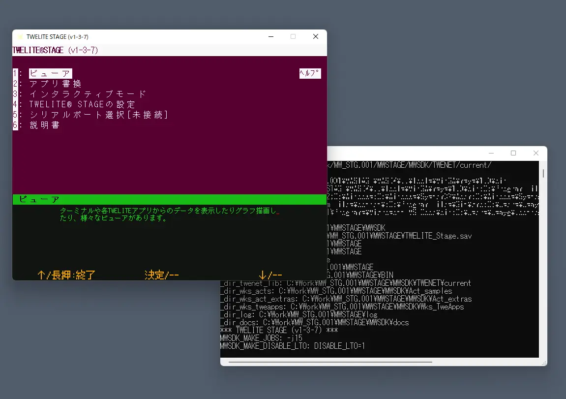
Screen example
Main operations on the main screen are:
- Left mouse click (select)
- Right double-click (go back to previous screen)
- Quickly press
ESCtwice, or once on some screens (go back) - Hold
Alt(⌘)key (help screen) - Normal keyboard input (follow screen instructions)
(Reference: TWELITE STAGE app manual)
2. Select serial port
This screen appears first when launching the TWELITE STAGE app. If TWELITE R or MONOSTICK is connected beforehand, it will be listed here. Select the TWELITE device to operate. You can also select it later by other operations.
Serial port selection screen
(Reference: TWELITE STAGE app manual)
3. Main menu
After exiting the serial port selection screen, the main menu appears. Select the “App write” menu to build and write.
Main menu
(Reference: TWELITE STAGE app manual)
4. App write menu
Before selecting the app write menu, confirm TWELITE connection and serial port selection. You can check the serial port selection status by holding the Alt(⌘) key to display the help screen.
App write menu
Projects accessible from the TWELITE STAGE app are categorized. The right Help shows related info in a browser. The Folder opens the project folder.
If TWELITE is connected, the model is identified when selecting the menu. (The app internally builds according to the identified TWELITE model.)
If an error occurs here, return to the main menu and reselect the menu. If unresolved, try clearing serial port selection with
Alt(⌘) + 0 in the TWELITE STAGE app, and check USB connections. Some USB errors require restarting your computer.(Reference: TWELITE STAGE app manual)
4. Select project
Here, select “act build & write” from the app write menu.
App write menu
5. Build & write
Here, select BRD_APPTWELITE in the project selection screen.
When selected, writing proceeds as shown in the screen example below. If an error appears, follow the instructions or go back and retry.
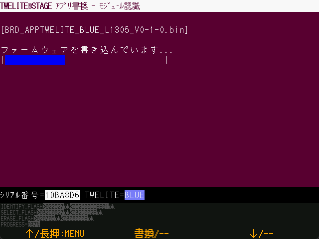
Writing in progress (with verify setting)
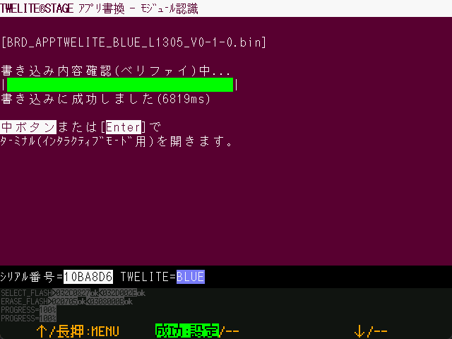
Write complete
(Reference: TWELITE STAGE app manual)
6. Move to interactive mode
After writing completes successfully, it proceeds to interactive mode (settings screen). The screen appears only if the firmware supports interactive mode.
In interactive mode, you can configure various settings such as the TWELITE wireless channel.
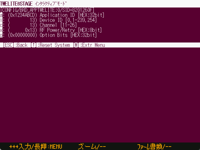
Interactive mode
(Reference: TWELITE STAGE app manual)
7. Terminal screen
Return to the root menu and select “Viewer” → “Terminal”.
A very simple serial terminal. You can check messages from TWELITE and send messages to TWELITE.
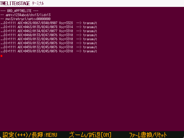
Terminal screen
The screen shows messages sent wirelessly approximately every second. You can also enter + + + to enter interactive mode screen.
(Reference: TWELITE STAGE app manual)
Building with VSCode
VSCode is a powerful editor for source editing, but you can also build firmware for TWELITE microcontrollers within VSCode.
Launch VSCode from the project list under the “Build & Write” menu in the TWELITE STAGE app.
Press the [VSCode] button on the right of the build list.

VSCode settings
This requires configuration in the TWELITE STAGE app.
Set “Open folder with code (VSCode)” to 1 in STAGE settings.
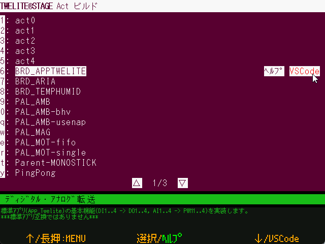
Open with VSCode
For Windows, Linux, and macOS, the executable
TWELITE_Stage_VSCode.{extension} with this setting enabled is distributed by default.If VSCode is already running, necessary settings may not be reflected. In that case, close VSCode and launch it again from the TWELITE STAGE app.
Because system environment variables are used for info reflection, problems may occur when running multiple TWELITE STAGE instances referencing different library folders simultaneously. If the environment variable MWSDK_ROOT is set correctly in the VSCode terminal, builds are expected to work properly.
VSCode build tasks
Open the workspace you want to build first. The workspace included with the TWELITE STAGE SDK has build task definitions.
Below is an example with an English interface, showing the opened workspace.
Open [Terminal>Run Task...].
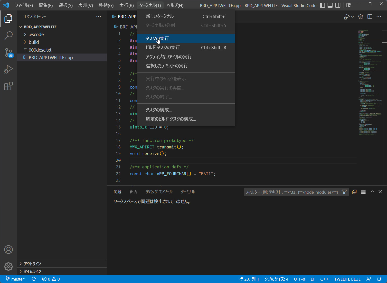
Run task menu
Select the TWELITE wireless module type (BLUE/RED) and act name to build. In the example below, Build for TWELITE BLUE is selected. The build starts immediately after selection.
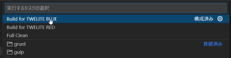
Select build task
Build progress is output in the terminal at the bottom.

Build progress
If built correctly, a message showing the .elf file generated with size info (text data bss dec hex filename) appears as shown in the inverted part of the example.
Also, a BIN file (e.g., BRD_APPTWELITE_BLUE_???.bin) should be created under the build folder. Please check.
The VSCode task definition includes a conversion for folder names incompatible with Windows file system (e.g., /c/User/... to C:/User/...).
The conversion rule in .vscode/tasks.json is not perfect but rewrites drive name parts in output messages to a format recognized by VSCode. This allows error file names and line numbers to be displayed in VSCode from compile messages.
...
"windows": {
    "command": "sh",
    "args": [
        "-c", "make TWELITE=BLUE 2>&1 | sed -E -e s#\\(/mnt\\)?/\\([a-zA-Z]\\)/#\\\\\\2:/#g"
    ],
If the build fails, first check the error messages. Messages containing the word error often help identify the cause easily.
Also, try cleaning (deleting intermediate files in objs_??? folders) and rebuilding. (If intermediate files from other environments remain, all operations including make clean may fail.)
Building from command line
Additional information for building from the command line.
Knowledge of command line (bash, zsh, etc.) usage is required.
Security warnings may appear when running executables depending on OS. Configuration to suppress warnings is needed. (Whether to operate with warnings suppressed should be decided by the customer or system administrator.)
Linux, macOS environment
Run make in a window running bash or zsh (or other shell). Confirm the environment variable MWSDK_ROOT is set correctly. For example, if installed at /work/MWSDK, add the following to ~/.profile or similar:
MWSDK_ROOT=/work/MWSDK
export MWSDK_ROOT
Run make from the command line. If make is missing, install the package.
On Linux, install via package manager (APT example):
sudo apt install makeor
sudo apt install build-essentialOn macOS, included in Command Line Tools for Xcode.
xcode-select --install
Windows environment
Run {MWSTAGE SDK installation}/MWSDK/WIN_BASH.cmd. Environment variables and make utility are set.
Build
Build as follows:
cd $MWSDK_ROOT
cd Act_samples/PingPong/build
pwd
/mnt/c/MWSDK/Act_samples/PingPong/build

ls
... list files

rm -rfv objs_*
... delete intermediate files just in case

make TWELITE=BLUE
... build for BLUE

make -j8 TWELITE=BLUE
... parallel build for BLUE (8 processes)
Command examples
See the Makefile explanation for details.
make TWELITE=BLUE: Build for TWELITE BLUEmake TWELITE=RED: Build for TWELITE REDmake cleanall: Delete intermediate files
About intermediate files
When building, objs_??? folders are created containing intermediate files. These files depend on the build environment, so leftover files from other environments cause make errors and build failures.
Deleting
objs_??? folders directly may resolve make errors.4.4 - Creating a New Project
Creating a new project
To create a new project, copy an existing sample act folder with a different name and edit the file names.
The destination folder does not have to be under the
MWSDK directory. However, the folder name must not contain spaces or Japanese characters.The project file structure is as follows (using PingPong as an example):
Act_samples
  +-PingPong
    +-PingPong.cpp   : Act file
    +-build          : Build folder
    +-.vscode        : VSCode configuration files
Copy this PingPong folder to another location (but the folder name must not contain Japanese characters or spaces).
SomeDir
  +-AlphaBravo
    +-PingPong.cpp -> AlphaBravo.cpp ※ Rename the file
    +-build          : Build folder
    +-.vscode        : VSCode configuration files
The only file that needs editing is the PingPong.cpp file name. Change it to the same name as the folder, AlphaBravo.cpp.
Run build\build-BLUE.cmd to generate the BIN file (on Windows 10).
On Linux/WSL/macOS, run make TWELITE=BLUE to verify that the build succeeds.
Editing the Build Definition
If you need to add files to the build target, edit build/Makefile. .c and .cpp files directly under the project folder are added automatically, but other files require manual editing.
See the Makefile documentation for editing instructions.
VSCode Configuration
If you use VSCode, edit the definitions under .vscode as needed.
Many samples included in the TWELITE STAGE SDK are set up as follows:
- The TWELITE STAGE SDK library source code references
${env:MWSDK_TWENET_LIBSRC}/include/**and${env:MWSDK_TWENET_LIBSRC}/src/**. This environment variableMWSDK_TWENET_LIBSRCis automatically set when opening the project from the TWELITE STAGE app in VSCode. - By default, no additional options such as
-Dare set for the build tasks.
4.5 - Installing VSCode for act
Install Visual Studio Code for act development
This page explains the introduction of VSCode for firmware development of the TWELITE wireless module. It does not cover general VSCode usage.
We apologize to those who arrived here via search engines.
We hope you will remember TWELITE, a wireless module characterized by ultra-low power consumption.
To facilitate writing the source code of act, we include configuration files for code interpretation in Visual Studio Code (VSCode).
VSCode reads source files and header files to interpret the source code, which helps with function definition information and completion of function and method names (LSP). Compared to traditional C libraries, the MWX library loads a larger amount of header files. Depending on your environment, the editor may feel slow.
To analyze source code and build from VSCode, information such as the folder where the library source code is stored is required. This information is reflected by launching VSCode from the TWELITE STAGE app. (Specifically, appropriate environment variables are set when starting VSCode. The project settings refer to these environment variables.)
Installing VSCode
Our support does not cover inquiries about how to install or use VSCode. Please refer to publicly available information.
Depending on your environment, security settings may be required for installation. Please check with your system administrator about installation feasibility and refer to official sources and general information for the procedure.
Features of VSCode
- Editing source code
- Intellisense based on source code interpretation(* This does not guarantee that all definitions are interpreted correctly)
VSCode can be downloaded from the official site.
Installing Plugins
To enable Visual Studio Code to interpret C/C++ language, install the following plugin:
- C/C++ for Visual Studio Code
Notes for Each OS
To launch VSCode from TWELITE STAGE, the code command must be enabled.
The following information is from code.visualstudio.com:
- Running Visual Studio Code on macOS https://code.visualstudio.com/docs/setup/mac
- Running Visual Studio Code on Windows https://code.visualstudio.com/docs/setup/windows
- Running Visual Studio Code on Linux https://code.visualstudio.com/docs/setup/linux
Notes
MWX library samples include a .vscode definition. This definition uses the MWSDK_ROOT environment variable to locate the library source code (under {MWSDK_ROOT}/TWENET/current).
When starting VSCode from TWELITE STAGE, the above environment variables and others are set. If VSCode is already running, these settings may not be applied.
VSCode’s source code interpretation does not always exactly match compiler interpretation (due to differences between GCC and clang, etc.). Also, depending on the editing state, interpretation may become more incomplete.
4.6 - Build Definition Makefile
Build definition with Makefile
The Makefile is stored in build/Makefile. By running the make command, the act is pre-defined to be built.
In MWSDK 2020-04, the .cpp files in the project folder are automatically detected, so usually there is no need to modify the Makefile.
Editing is required when source files are placed in subfolders.
In MWSDK 2019-12 and earlier, if there are multiple .cpp files, editing the Makefile is necessary.
After copying the project folder from another environment, always delete the build/objs_??? folder. If intermediate files from another environment remain, make will result in an error.
(From MWSDK 2020-04 onwards) You can avoid errors by running clean with USE_APPDEPS=0 and then running the make command again.
make USE_APPDEPS=0 TWELITE=BLUE clean
...
make TWELITE=BLUE
make parameters
TWELITE=
Specify the build target as BLUE or RED. For TWELITE BLUE, specify make TWELITE=BLUE.
all
Executes the build. Usually omitted, and run like make TWELITE=BLUE.
clean
Deletes intermediate build files. Run like make TWELITE=BLUE clean.
cleanall
Deletes all intermediate files. Run like make cleanall. This is equivalent to deleting all objs_??? folders in the build folder.
USE_APPDEPS=0 or 1
Setting 1 (default) determines build files based on file dependencies. For example, if a header file changes, related source files will be recompiled.
Setting 0 disables dependency evaluation. If set to 0, make will not error even if inconsistent intermediate files remain.
Makefile definition
Depending on the size of the act and when defining behaviors, source files are usually split and built.
One of the build files is project_folder_name.cpp.
If you want to define other files, edit the build/Makefile in the project folder.
Below is an example Makefile from the sample PAL_AMB-behavior.
##############################################################################
# Copyright (C) 2019 Mono Wireless Inc. All Rights Reserved.
# Released under MW-SLA-*J,*E (MONO WIRELESS SOFTWARE LICENSE
# AGREEMENT).
##############################################################################
# USER PROJECT BUILD DEFINITION.
##############################################################################

#####################################################################
## set TWELITE model
TWELITE ?= BLUE
#TWELITE = RED

#####################################################################
## set application version (MUST SET THIS.)
VERSION_MAIN = 0
VERSION_SUB  = 1
VERSION_VAR  = 0

#####################################################################
## set an additional source file
##   the default file name is dirname.

## for C++ files compiled with g++ (must have .cpp suffix)
APPSRC_CXX += myAppBhvParent.cpp
APPSRC_CXX += myAppBhvParent-handlers.cpp
APPSRC_CXX += myAppBhvChild.cpp
APPSRC_CXX += myAppBhvChild-handlers.cpp

## for C files compiled with gcc (must have .c suffix)
#APPSRC += my_c_file.c

## Additional Src/Include Path
# if set, find source files from given dirs.
#
APP_COMMON_SRC_DIR_ADD1 = ../Parent
APP_COMMON_SRC_DIR_ADD2 = ../Child
#APP_COMMON_SRC_DIR_ADD3 =
#APP_COMMON_SRC_DIR_ADD4 =

#####################################################################
## set misc option for compiler

## C++ flags passed to g++
# e.g. CXXFLAGS += -DMY_DEFS
#CXXFLAGS +=

## C++/C flags passed to g++/gcc
# e.g. CFLAGS += -DMY_DEFS
#CFLAGS +=

## include opts
# e.g. INCFLAGS += -I../my_common_src/
#INCFLAGS +=

## optimize flag (default is -Os, normally no need to change)
#OPTFLAG=-O2

#####################################################################
## must include mwx.mk (the makefile body part.)
MWSDK_PATH?=$(realpath $(MWSDK_ROOT))
include $(MWSDK_PATH)/MkFiles/mwx.mk
#####################################################################
VERSION_???
Specify the version number. It will be reflected in the built file name.
## set application version (MUST SET THIS.)
VERSION_MAIN = 0
VERSION_SUB  = 1
VERSION_VAR  = 0
During compilation, these are passed as definitions like -DVERSION_MAIN=0 -DVERSION_SUB=1 -DVERSION_VAR=0.
Adding source files
(From MWSDK 2020-04 onwards) If files are not placed in subfolders, no additional specification is required. All
.c and .cpp files in the project folder are added automatically.What is needed when adding source files are APPSRC_CXX and APP_COMMON_SRC_DIR_ADD?.
When placing source files in subfolders, specifying the folder
APP_COMMON_SRC_DIR_ADD? is mandatory.Append the source file names to APPSRC_CXX. These file names must not include folder names. Even if they are in subfolders, specify them without folder names (i.e., if the same file name exists in multiple subfolders, the build will fail).
APPSRC_CXX += myAppBhvParent.cpp
APPSRC_CXX += myAppBhvParent-handlers.cpp
APPSRC_CXX += myAppBhvChild.cpp
APPSRC_CXX += myAppBhvChild-handlers.cpp
Next, specify the search paths if source files are stored outside the project folder. You can set up to four.
APP_COMMON_SRC_DIR_ADD1 = ../Parent
APP_COMMON_SRC_DIR_ADD2 = ../Child
Folder paths are relative to the Makefile.
Compiler and linker options
You can also pass several other options to the compiler and linker.
| Option | Description |
|---|---|
CXXFLAGS | Specify compile options for C++ source files. |
CFLAGS | Specify compile options for C/C++ source files. |
INCFLAGS | Specify include paths for header files. |
OPTFLAGS | Define when you want to apply compile options other than the default -Os for special reasons. |
LDFLAGS | Specify linker options. (Although not mentioned in the comments of the above Makefile, you can specify this.) |
4.7 - Other Platforms
Using other platforms
Build definitions are prepared so that some functions (serparser, pktparser, Serial objects for console) can be built on other platforms as well. Only the necessary files are extracted.
Build definitions are stored in the {mwx library directory}/stdio folder. For build instructions, please refer to README.md (link is on GitHub).
- Must be able to compile with C++11.
- Must have access to C++11 standard library headers (such as utility, algorithm, functional, iterator).
new/delete/virtualare not used.- Memory allocation using
newmay be used exceptionally.- In
serparser/pktparser,deleteis used in alloc_heap that uses thenewoperator. - (Reference) However, some parts of the
mwxlibrary are designed under the assumption thatdeleteis not considered.
- In