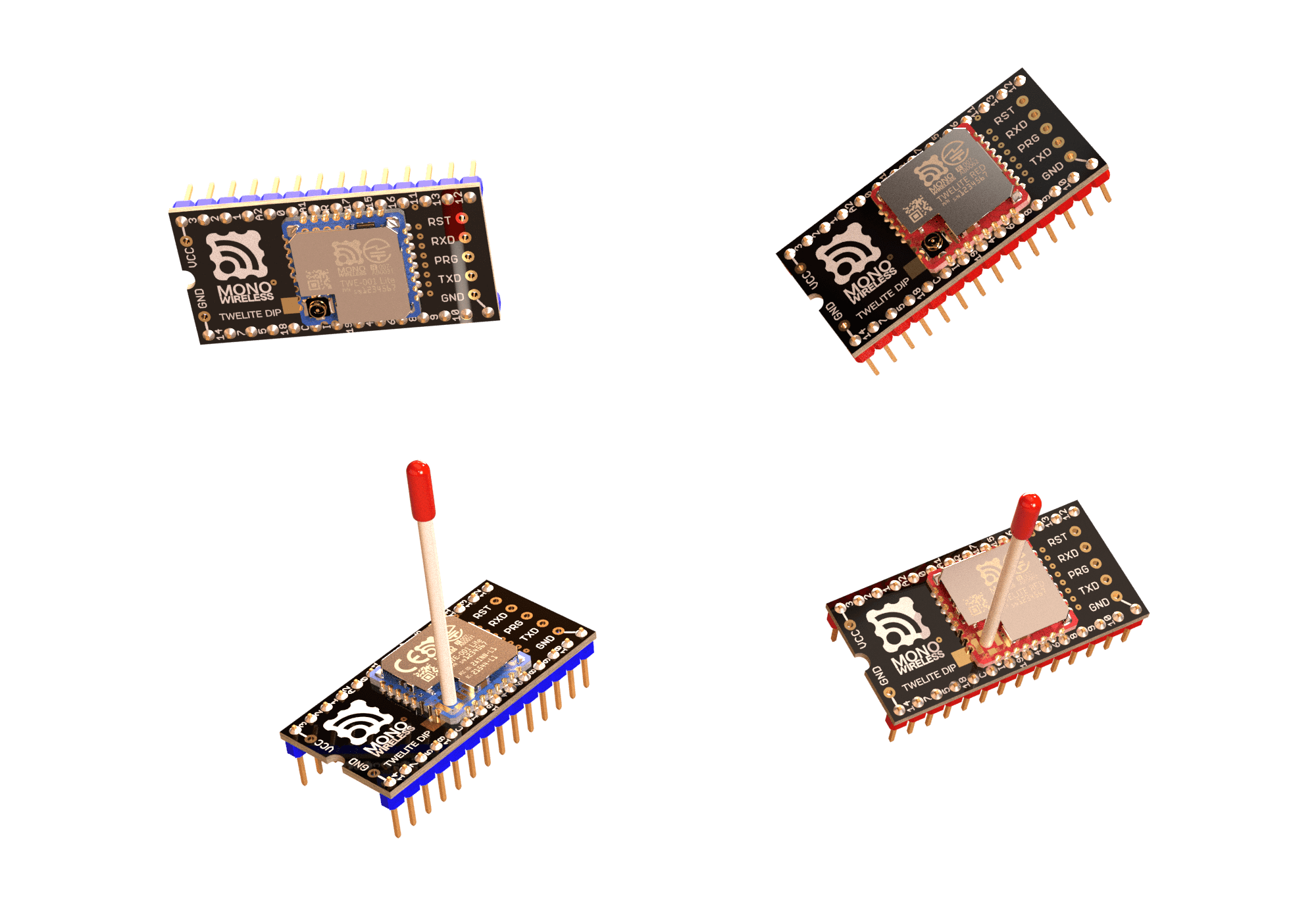
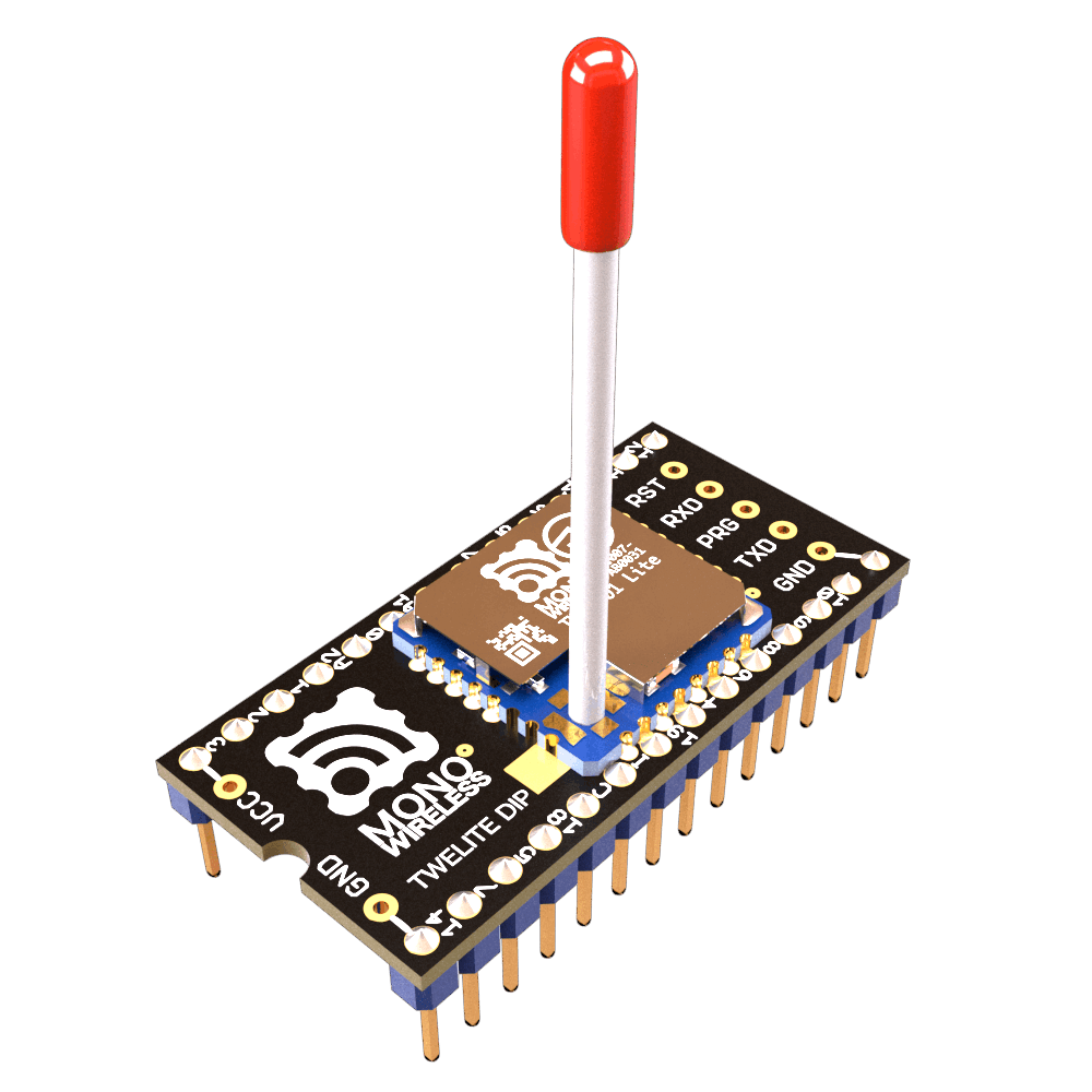
The Extremely Simple! Wireless Module TWELITE DIP is a product with TWELITE mounted on a 2.54mm pitch board. It is suitable for prototyping and small-scale production because it can be easily wired by hand.
TWELITE can communicate immediately after startup. Pairing like Bluetooth is not required.
Broadcast communication is performed between devices set to the same frequency channel. Therefore, multiple devices cannot transmit simultaneously on the same channel. Packets not addressed to the device are ignored. You can think of it as working like a transceiver or intercom.
TWELITE can transmit without receiving, enabling the realization of devices with excellent power-saving performance.
What is the wireless communication standard?
TWELITE is a wireless module that uses 2.4GHz radio waves and complies with IEEE 802.15.4, which is a different standard from Bluetooth (IEEE 802.15.1). Other products conforming to IEEE 802.15.4 include Zigbee modules, but TWELITE is not a Zigbee module. Zigbee modules use the Zigbee protocol stack on top of IEEE 802.15.4, whereas TWELITE implements a simple, proprietary protocol stack instead.
Although it is not suitable for large-volume data communication, it is optimal for simple signal transmission and similar applications.
Small amounts of data can be transmitted efficiently.
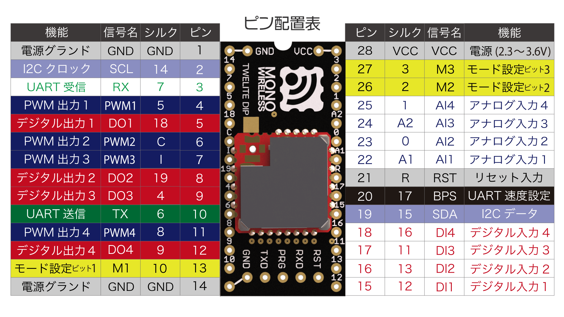
Pin Functions
Pin Layout Table
The pins used by the Extremely Simple! Standard App have several functions.
Transmit digital and analog signals using the Extremely Simple! Standard App
Extremely Simple! The Extremely Simple! Standard App (App_Twelite) allows you to achieve basic signal transmission just by wiring.
Using the Extremely Simple! Standard App pre-installed on the factory-default TWELITE DIP, let’s try reflecting the signal input to one DIx/AIx port onto the other DOx/PWMx port.
TWELITE DIP can be either the BLUE series or the RED series.
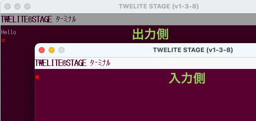
One-Way Signal Transmission
Signals input to the Parent can be output from the Child.
The Parent sends data to all Children
When multiple Children are prepared, the Parent’s DIx can simultaneously control the DOx of all Children.
Digital Signal
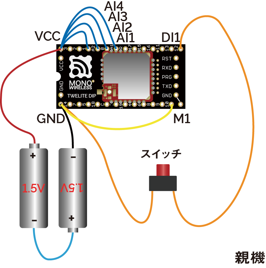
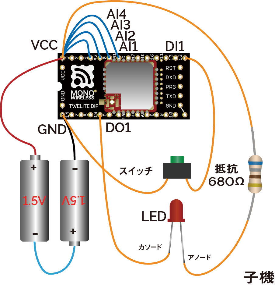
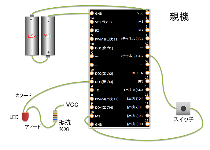
Pressing the switch connected to the Parent lights the LED connected to the Child, and releasing the switch on the Parent turns off the LED on the Child.
Parent Wiring
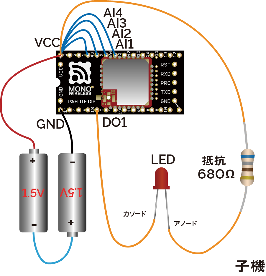
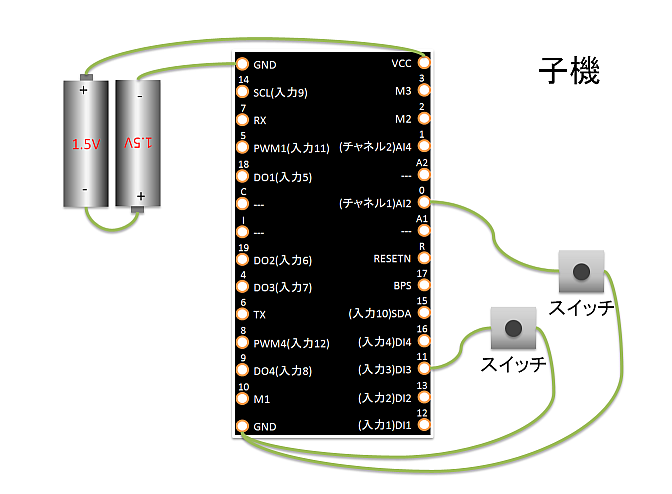
Child Wiring
In the above example, only DI1 and DO1 are used, but there are a total of 4 ports. Other ports can be used similarly.
Connect the M1 pin of one TWELITE DIP to GND. This unit will act as the Parent.
Also, connect unused AIx ports to VCC to disable them (this can be omitted by changing settings in Interactive Mode).
Please connect a current-limiting resistor to the LED.
Output current capacity is limited
Supply Voltage
Drive Capacity
2.7V-3.6V
4mA
2.2V-2.7V
3mA
2.0V-2.2V
2.5mA
If exceeding the drive capacity, please use a MOSFET or transistor.
Analog Signal
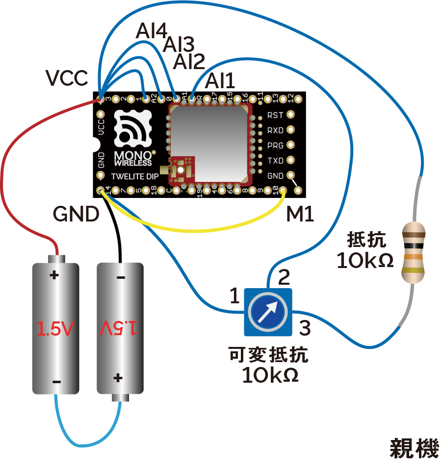
Turning the potentiometer connected to the Parent changes the brightness of the LED connected to the Child.
Parent Wiring
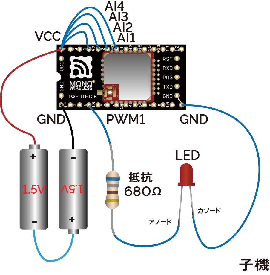
Child Wiring
In the above example, only AI1 and PWM1 are used, but there are a total of 4 ports. Other ports can be used similarly.
About input/output voltage
The analog input operates at 2.0V or below.
In the above example, the supply voltage is divided in half by a potentiometer (10KΩ) and a resistor (10KΩ). In the initial state of the Extremely Simple! Standard App, the output adjusted for the potentiometer is applied to PWMx. When the duty cycle is \(duty\), the input voltage \(V_{input}\), and the supply voltage \(V_{cc}\), the calculation formula is as follows:
\(duty=min(230\frac{V_{input}}{V_{cc}}-5, 100)\)
If you set the option bit 0x00000040 using Interactive Mode, full scale output is possible for inputs below 1.8V (inputs above 2.0V are treated as unused).
\(duty=100\frac{min(V_{input}, 1.8)}{1.8}\)
If anything is wired to PWM2 or PWM3, firmware writing may fail.
These pins have functions used during firmware writing (Details).
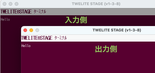
Two-Way Signal Transmission
Signal transmission can be performed not only from Parent to Child but also from Child to Parent in the same way.
The Parent receives data from all Children
When multiple Children are prepared, the exclusive DIx of each Child can control the Parent’s DOx in parallel.
(Example: Reflect one Child’s DI1 to the Parent’s DO1, and another Child’s DI2 to the Parent’s DO2)
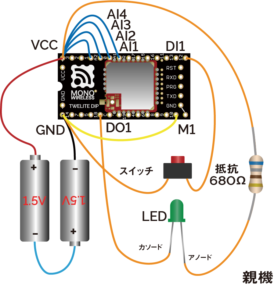
Pressing the switch connected to the Parent lights the LED connected to the Child, and releasing the switch on the Parent turns off the LED on the Child.
At the same time, pressing the switch connected to the Child lights the LED connected to the Parent, and releasing the switch on the Child turns off the LED on the Parent.
Parent Wiring
Child Wiring
In the above example, only DI1 and DO1 are used, but there are a total of 4 ports. Other ports can be used similarly.
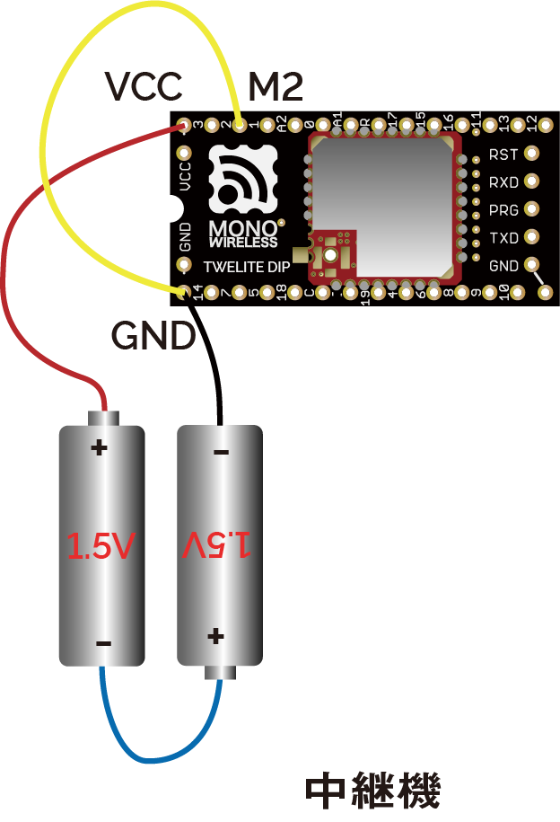
Installing a Repeater
By placing a unit configured as a Repeater between the Parent and Child, communication distance can be extended. Up to 3 stages of repeaters can be used.
By using Interactive Mode, you can change various parameters such as network grouping and enabling low latency mode.
What is Interactive Mode
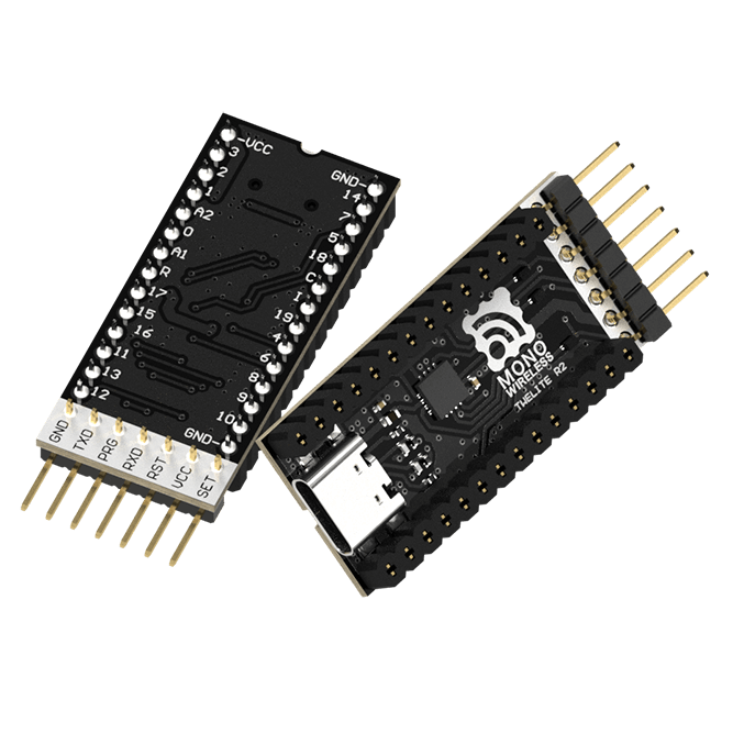
Interactive Mode is a mode used when connecting the TWELITE series to a PC for configuration. By connecting the TWELITE series to a PC via a USB adapter TWELITE R series, you can change various parameters through UART communication.
We recommend using the TWELITE STAGE app. The TWELITE STAGE app is a tool that includes functions for firmware configuration and writing, as well as features to evaluate communication with the parent device. The TWELITE STAGE app is included in the TWELITE STAGE SDK.
For more details about the TWELITE STAGE app, please refer to the TWELITE APPS Manual.
Prepare a pair of parent and child devices and configure so that transmission occurs only when the parent’s button is pressed
Network Grouping
By default, all TWELITE DIP devices can communicate with each other. When you prepare two pairs of parent and child devices, the inputs of the parent are reflected to both children, and the inputs of the children are reflected to both parents.
Using Interactive Mode, change the Application ID and frequency channel to separate the two pairs so they can be used independently at the same time.
The Application ID logically separates the network, and the frequency channel physically separates it. If the number of groups is 16 or less, it is recommended to change both.
It is recommended to space frequency channels as much as possible.
Customization Procedure
Insert the TWELITE DIP into the TWELITE R2 and connect it to the PC using a USB-C cable
Pressing the switch on Group A’s parent lights only Group A’s child LED
Pressing the switch on Group B’s parent lights only Group B’s child LED
Change the Application ID of Group B’s child to 0xAAAAAAAA and the frequency channel to 11.
Pressing the switch on Group A’s parent lights LEDs on both children
Using Low Latency Mode
By default, there is a delay of about 30-70ms from when the source DIx changes until it is reflected on the destination DOx. This delay exists due to processing to avoid chattering and wireless packet interference.
Low Latency Mode shortens this delay to about 3-10ms by simplifying these processes.
Enable low latency mode on the transmitting device (parent) via Interactive Mode.
The option bits value is a 32-bit unsigned integer. You can enable corresponding settings by setting flags on each bit.
To enable multiple settings simultaneously, take the logical OR of all.
Customization Procedure
Insert the TWELITE DIP into the TWELITE R2 and connect it to the PC using a USB-C cable
Pressing the parent’s switch lights the child’s LED
The operation is the same as the default state, but you might notice slightly improved response
Connect an oscilloscope to the parent’s DO1 and child’s DI1 to compare and confirm the effect
Transmit Only When Button is Pressed
By default, transmission occurs when the input state changes and also once every second.
In this case, for example, if the transmitting device’s button is held down and the power is cut, the output on the receiving side remains.
The Transmit Only When Button is Pressed setting causes the transmitting device to repeatedly send when DIx is Low, and continue sending for one second after transitioning to High. If the receiving device’s DOx is set Low and reception stops, it returns to High.
Change the setting via Interactive Mode to transmit only when the button is pressed.
This is useful for applications such as rotating a motor while a remote control button is pressed.
Since transmission continues at short intervals while DIx is Low, increasing the number of transmitters on the same frequency channel is not recommended. Apply this option only for 1:1 communication.
Set the Interactive Mode values as follows to change the behavior of digital input/output on the transmitting device (parent) and receiving device (child).
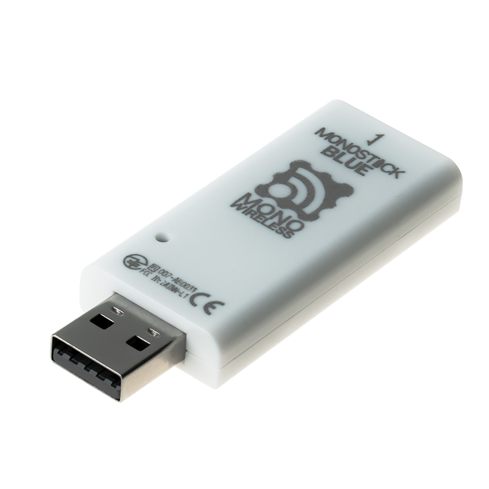
Connect the Parent to a PC and send/receive data via UART
By using UART communication, you can integrate the Parent with a PC.
Use the TWELITE STAGE app and Python scripts to communicate over UART, allowing you to acquire and control Child device data from your PC via the Parent.
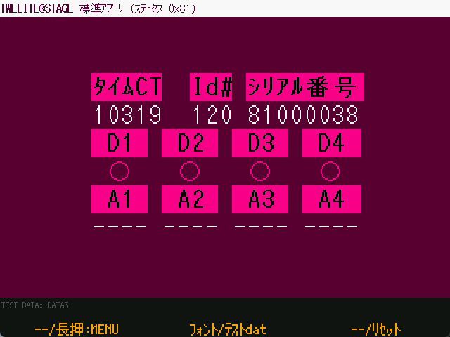
The data sent from the Child running the Extremely Simple! Standard App includes information such as the input state of the DIx/AIx ports, power supply voltage, and the logical device ID of the sender.
Displaying Serial Strings
Data received by the Parent from the Child can be obtained by interpreting the strings output by the Parent over serial (UART). Let’s display this string first.
The default serial communication settings are 115200bps 8-N-1.
When data is received from the Child, a message like the following will be displayed:
:78811501C98201015A000391000C2E00810301FFFFFFFFFB
By interpreting such strings output by the Parent, you can obtain the data sent by the Child.
The above string represents the following data
#
Data
Description
Value
:
char
Header
:
78
0
uint8
Sender Logical Device ID
0x78
81
1
uint8
Command Number
0x81
15
2
uint8
Packet Identifier
0x15
01
3
uint8
Protocol Version
0x01
C9
4
uint8
LQI
201/255
8201015A
5
uint32
Sender Serial ID
0x201015A
00
9
uint8
Destination Logical ID
0x00
0391
10
uint16
Timestamp
approx. 14.27 seconds
00
12
uint8
Number of Relays
0
0C2E
13
uint16
Power Supply Voltage
3118mV
00
15
int8
-
81
16
uint8
Digital Signal
DI1LDI2H DI3HDI4H (Periodic Tx)
03
17
uint8
Digital Signal Mask
DI1DI2
01
18
uint8
AI1 Converted Value
16mV
FF
19
uint8
AI2 Converted Value
Not used
FF
20
uint8
AI3 Converted Value
Not used
FF
21
uint8
AI4 Converted Value
Not used
FF
22
uint8
AIx Correction Value
AI10x03
FB
uint8
Checksum
0xFB
char
Footer
\r
char
Footer
\n
The strings output by the TWELITE Parent follow the format below:
Header
Payload
Checksum
Footer
:
repeated 00-FF
LRC8 of payload
CRLF
All ASCII characters*
Starts with : (0x3A)
Ends with CRLF (\r\n/0x0D 0x0A)
Big-endian
*Except for binary format in serial communication apps
Standard App Viewer
The above format is machine-friendly, but to check the content as a human, you need to interpret it. The TWELITE STAGE app provides a function to interpret and display strings representing data sent from Children running the Extremely Simple! Standard App. The Python library described below also performs this interpretation.
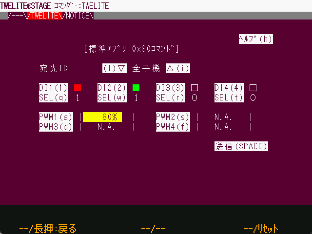
Commander sends strings from the PC to the Parent over serial communication. In other words, it works in the opposite direction to the Standard App Viewer.
Both the “Standard App Viewer” and “Commander” in the TWELITE STAGE app simply exchange strings over serial communication. If you have an environment that supports serial communication, you can integrate your own application with the Parent.
Here, let’s use a Python script to display the input state of DI1, and then control the output of DO1.
By leveraging Python scripts, you can process and save received data, or control output ports from your own software.
This section assumes the reader has knowledge and experience with Python.
Installing the MWings Library
The MWings library makes it easy to integrate TWELITE and Python scripts. Specifically, it interprets strings representing data received from the Child and constructs data to be sent to the Child.
This creates a Twelite object, which serves as the interface for communicating with the Parent.
You specify the serial port as an argument, but here we use the mw.utils.ask_user_for_port() utility to select it dynamically. This function outputs an error message if no serial port exists, returns the port if only one is found, or prompts the user if multiple are present.
Registering a Receive Event Handler
@twelite.on(mw.common.PacketType.APP_TWELITE)
defon_app_twelite(packet):
if packet.di_state[0]:
print("DI1 Pressed")
This registers an event handler that is called when a packet is received from a Child running the Extremely Simple! Standard App.
Event handler registration uses a Python decorator (?). Here, since we are targeting data from the Extremely Simple! Standard App (App_Twelite), we use @twelite.on(mw.common.PacketType.APP_TWELITE). The function defined immediately after this decorator becomes the handler. The function name can be anything, but it must be defined after initializing the Twelite object.
To detect when the Child’s DI1 becomes Low, the receive handler checks the first boolean value in the List-like object di_state (digital interface state) of the packet variable (mwings.parsers.app_twelite.ParsedPacket). Each value in di_state is True when Low.
Handling Other Data
The packet variable contains not only input states but also information about the sender and receiver. For example, by using to_json(), you can output all data in JSON format as follows:
This creates a Twelite object, which serves as the interface for communicating with the Parent.
You specify the serial port as an argument, but here we use the mw.utils.ask_user_for_port() utility to select it dynamically. This function outputs an error message if no serial port exists, returns the port if only one is found, or prompts the user if multiple are present.
This initializes a command object (mwings.serializers.app_twelite.Command), which represents the packet to be sent to a Child running the Extremely Simple! Standard App.
The dictionary initial represents the initial state of the command. Here, the destination logical device ID is set to 0x78 (all Children), with DI1 as the target for change, and initially set to High.
Here, the command data is converted to a string and sent to the Parent every second.
Blinking is achieved by toggling the first boolean value in the List-like object di_state (digital interface state) of the command data, which controls the state of DOx.
Rewrite the TWELITE firmware to the Serial Communication App (App_Uart), which is specialized for wireless serial communication. While the “Extremely Simple! Standard App” also has a function for transmitting binary data via serial communication, its functionality is very limited.
Press Enter several times until the write is complete
By default, after a successful write, the device transitions to the following Interactive Mode screen.
--- CONFIG/TWE UART APP V1-04-5/SID=0x82018ca0/LID=0x78 -- ---
 a: set Application ID (0x67720103)
 i: set Device ID (120=0x78)
 c: set Channels (18)
 x: set RF Conf (3)
 r: set Role (0x0)
 l: set Layer (0x1)
 b: set UART baud (38400)
 B: set UART option (8N1)
 m: set UART mode (E)
 k: set Tx Trigger (sep=0x0d0a, min_bytes=0 dly=0[ms])
 h: set header format [;U;%t;%i;0x%A;%q;%s;<*>;%X;\n]
 C: set crypt mode (0)
 o: set option bits (0x00000100)
---
 S: save Configuration
 R: reset to Defaults
List of Communication Modes
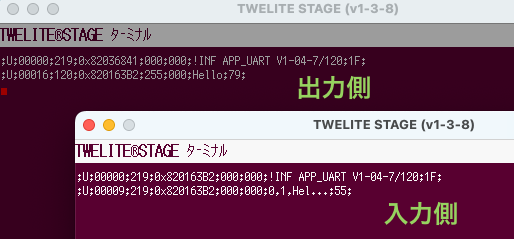
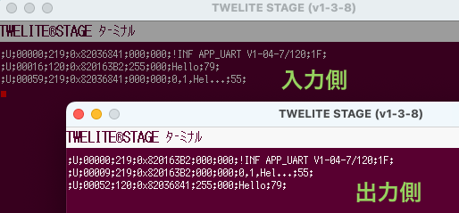
The Serial Communication App provides five communication modes, allowing you to select the most suitable one for your application.
Format Mode (ASCII): Applies a format to both transmission and reception.
Format Mode (Binary): The binary version of Format Mode (ASCII).
Set the i: Logical Device ID to 0 (Parent) on one terminal, and to 1 (Child, ID 1) on the other.
For an overview and usage instructions for Interactive Mode, please refer to the TWELITE APPS Manual.
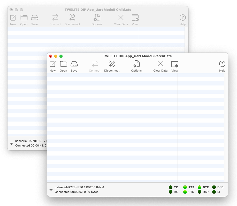
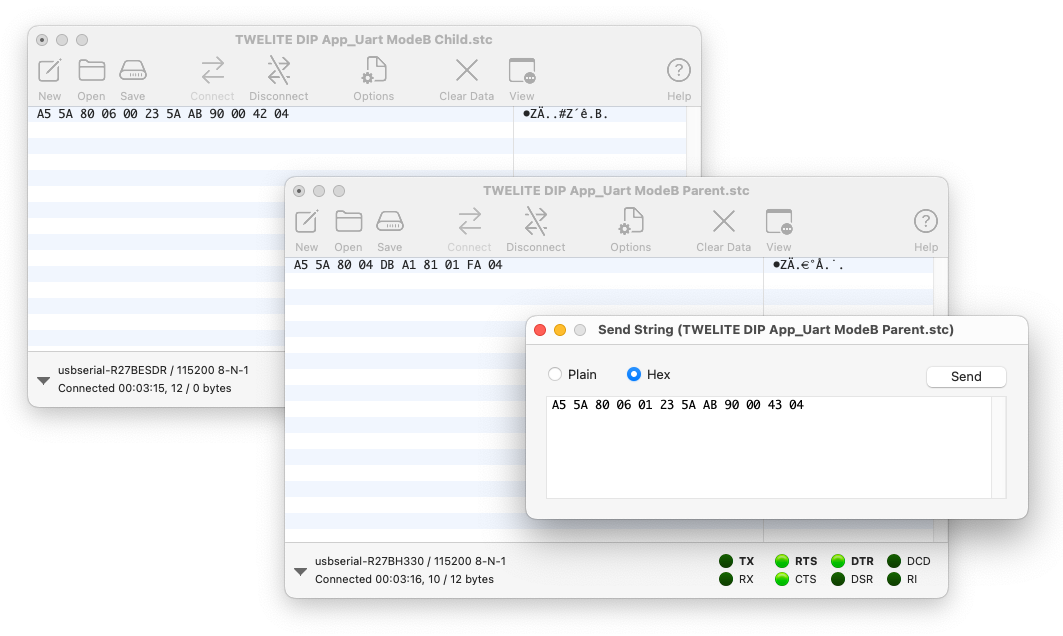
Prepare an Environment that Supports Binary Data
The terminal features of the TWELITE STAGE App and TeraTerm do not support binary data. You need to use a terminal software that supports binary format.
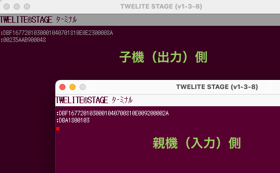
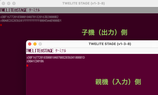
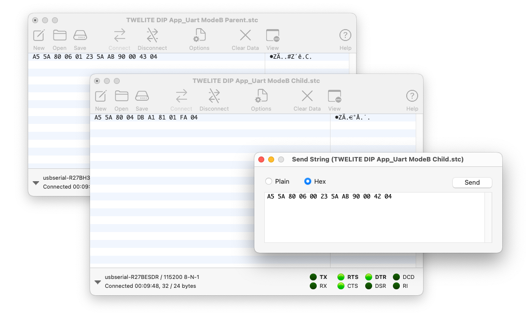
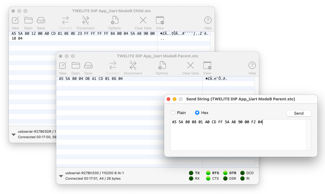
For the sender’s response message format A5 5A 80 04 DBA1..., see the manual.
3. Sending from the Child Side
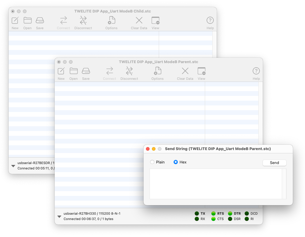
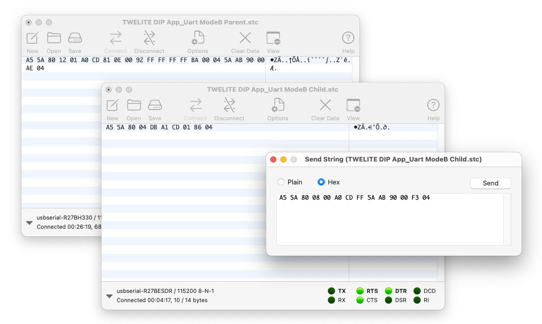
Just as with the Parent, select the Child window, then go to Connection > Send String... to open the send window, and make sure the Hex radio button is selected.
Enter the following content and click Send to transmit to the Parent.
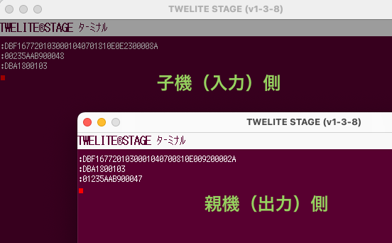
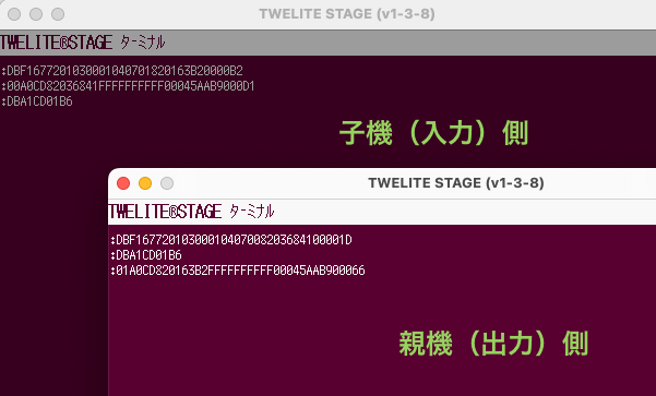
For the sender’s response message format A5 5A 80 04 DB A1..., see the manual.
3. Send from the Child Side
As with the Parent, select the Child window, then go to Connection > Send String... to open the send window, and make sure the Hex radio button is selected.
Enter the following and click Send to transmit to the Parent.
5 - Advanced Digital Transmission with Remote Control App
Use the Remote Control App to access advanced features specialized for digital signals
By writing the firmware from Extremely Simple! Standard App (App_Twelite) to the Remote Control App (App_IO), you can access advanced features specialized for digital signals.
Use the Remote Control App to utilize advanced features specialized for digital signal transmission. For example, you can increase the number of Child digital inputs to 12 channels.
Write the TWELITE firmware to the Remote Control App (App_IO), which is specialized for digital signal transmission. While the Extremely Simple! Standard App supports digital signal transmission, its I/O is limited to 4 lines. The Remote Control App expands the number of I/O and allows you to switch their combinations.
Writing the Firmware
Write the firmware to all Parent, Child, and other devices as follows:
Press Enter several times until writing is complete
With the default settings, after a successful write, the device will switch to the following Interactive Mode screen:
--- CONFIG/APP_IO V1-03-2/SID=0x86300001/LID=0x00 ---
 a: set Application ID (0x67720107)
 i: set Device ID (--)
 c: set Channels (16)
 x: set Tx Power (3)
 t: set mode4 sleep dur (1000ms)
 y: set mode7 sleep dur (0s)
 f: set mode3 fps (16)
 d: set hold mask (000000000000)
 D: set hold dur (1000ms)
 o: set Option Bits (0x00000000)
 b: set UART baud (38400)
 p: set UART parity (N)
 C: set crypt mode (0)
 K: set crypt key []
---
 S: save Configuration
 R: reset to Defaults
In the default state, the Parent can receive up to 12 digital signals.
Parent wiring diagram
In the diagram above, DIP pin 9 (O3) is used as an output, but other Ox pins can be used similarly. To test the channel override function, which is not available in the Extremely Simple! Standard App, a tactile switch is connected to DIP pin 23 (C1).
Child Wiring
In the default state, the Child can send up to 12 digital signals.
Child wiring diagram
In the diagram above, DIP pin 17 (I3) is used as an input, but other Ix pins can be used similarly. Similarly, to test the channel override function, a tactile switch is connected to DIP pin 23 (C1).
Operation Check
Press and release the button connected to the Child’s I3.
The LED connected to the Parent’s O3 will turn on and off accordingly.
While pressing the button connected to the Child’s C1, press and release the button on I3.
Communication will not occur because the Child’s frequency channel is temporarily overridden.
While pressing the buttons connected to both the Parent’s and Child’s C1, press and release the button connected to the Child’s I3.
Communication will resume because both Parent and Child frequency channels are overridden to match.
The C1/C2 pins override the frequency channel as follows:
Compared to the Extremely Simple! Standard App, you can handle two more digital signals!
Reflecting Child Input to Parent Output as Fast as Possible
When using the Child’s continuous mode, there is usually a delay of about 30-70ms from Child input to Parent output. If you need faster response, set Option Bits 0x00000001: Low Latency Mode via Interactive Mode.
Press Enter and confirm that the settings list is shown
Enter o (lowercase), input the Option Bits value 00000001, and press Enter
Enter S (uppercase) to save, then press ESC to exit
If multiple inputs change almost simultaneously, they are transmitted in order, which may cause delays for subsequent inputs.
Also, if input chattering occurs, it may be reflected directly to the output.
When Low Latency Mode is applied to the Child’s intermittent mode, its behavior differs from continuous mode:
Upon wake-up by interrupt, only the value of the corresponding interrupt port is sent
If a port is used as an interrupt wake-up pin, the states of other ports cannot be read simultaneously upon wake-up
When returning from sleep, the IO port state is determined in 1/4 the usual time
Best suited for sending digital outputs from sensors, rather than buttons that may have chattering!
Restoring Output Signals When Packets Are Lost
If radio communication is interrupted while any input is held Low, the output will remain Low even if the actual input returns to High.
To return the signal to its original state when packets are lost, enable Remote Long Press Mode. In this mode, after the sending side input changes, the signal is sent continuously for a while. On the receiving side, if no packet indicating a Low state is received for a certain period, the output times out and returns to High.
Press Enter and confirm that the settings list is shown
Enter o (lowercase), input the Option Bits value 00000100 and press Enter
Enter d (lowercase), input the hold/long-press target (for example, 000000001010 for O2 and O4), and press Enter
Enter D (uppercase), input the hold/long-press time (the duration to return the output from Low to High after signal loss), and press Enter
Enter S (uppercase) to save, then press ESC to exit
Ideal for applications such as remotely controlling motors from a remote control!
Using the Child as a Low Power Remote
If the Child is battery-powered, intermittent mode, which alternates sleep and wake, is effective. By combining Low Latency Mode and Hold Mode, the Parent’s output can be maintained for a set time when the Child’s button is pressed.
Press Enter and confirm that the settings list is shown
Enter d (lowercase), input the hold/long-press target (for example, 000000001010 for O2 and O4), and press Enter
Enter D (uppercase), input the hold/long-press time (hold time), and press Enter
Enter S (uppercase) to save, then press ESC to exit
Set the hold/long-press time according to your remote control requirements. For example, to keep a lamp on for a while when a button is pressed, use a longer time such as 3000 ms; for frequent button operations, a shorter time such as 50 ms is suitable.
Ideal for applications such as remotely controlling LEDs from a low-power remote!
Using the Child as a Low Power Remote with Long Press
If the Child is battery-powered, intermittent mode is effective. By combining Low Latency Mode and Remote Long Press Mode, the Child can continuously send data to the Parent while a button is held. Even after the button is released, the Child continues sending for a set period, and on the Parent side, if radio packets indicating the button remains pressed are lost for a set period, the output returns to its original state. This ensures reliable delivery of the Child’s input even in low-power operation.