DIx/AIx port onto the other DOx/PWMx port.Products Used
 |
|---|
| TWELITE DIP |
| TWELITE Parent / Child / Repeater |
| Extremely Simple! Standard App |
| 2 units (3 units when using a Repeater) |
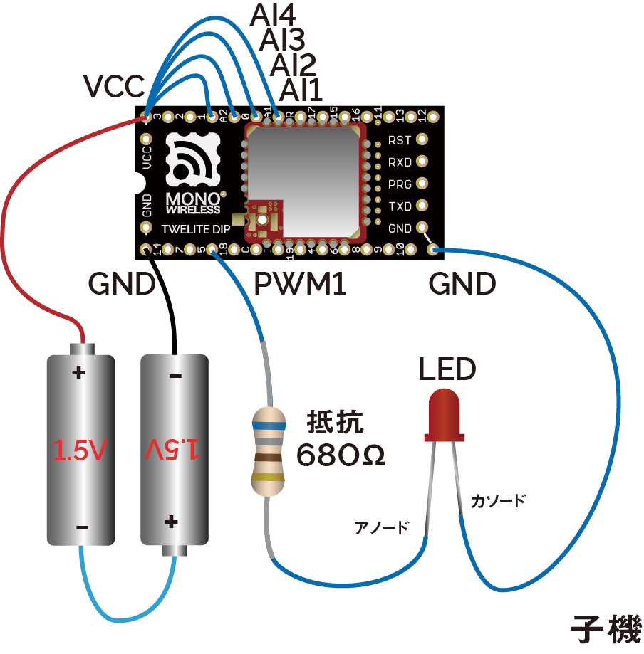
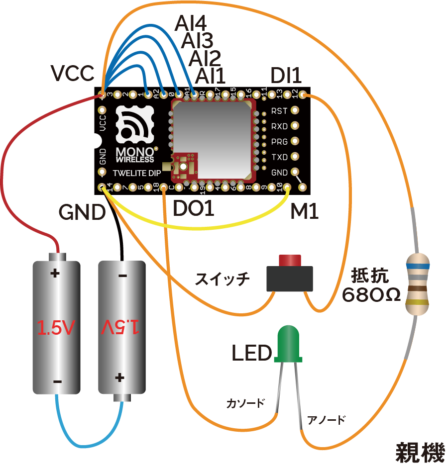
One-Way Signal Transmission
Signals input to the Parent can be output from the Child.
The Parent sends data to all Children
DIx can simultaneously control the DOx of all Children.Digital Signal
Pressing the switch connected to the Parent lights the LED connected to the Child, and releasing the switch on the Parent turns off the LED on the Child.
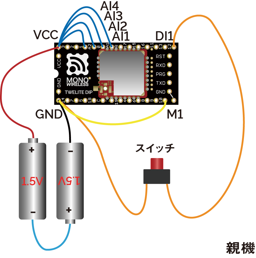
Parent Wiring
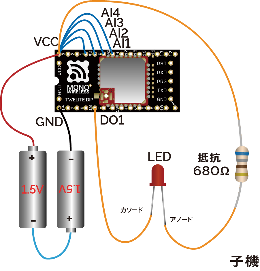
Child Wiring
In the above example, only DI1 and DO1 are used, but there are a total of 4 ports. Other ports can be used similarly.
Connect the M1 pin of one TWELITE DIP to GND. This unit will act as the Parent.
Also, connect unused AIx ports to VCC to disable them (this can be omitted by changing settings in Interactive Mode).
Output current capacity is limited
| Supply Voltage | Drive Capacity |
|---|---|
| 2.7V-3.6V | 4mA |
| 2.2V-2.7V | 3mA |
| 2.0V-2.2V | 2.5mA |
If exceeding the drive capacity, please use a MOSFET or transistor.
Analog Signal
Turning the potentiometer connected to the Parent changes the brightness of the LED connected to the Child.
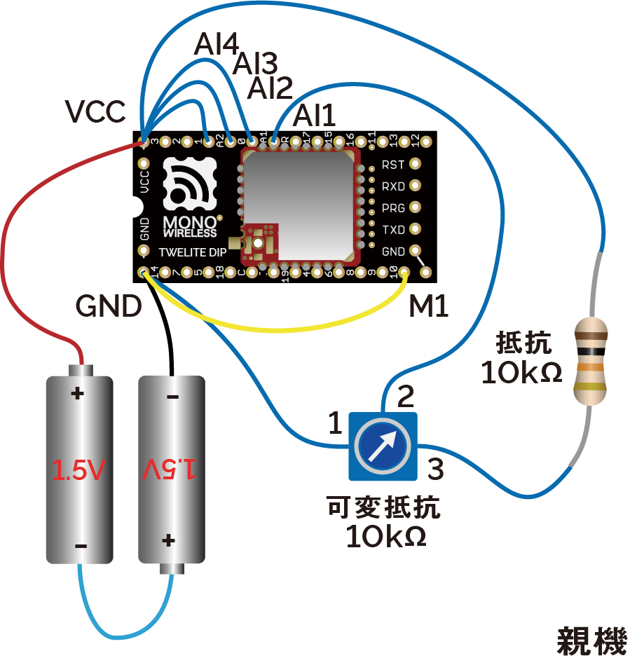
Parent Wiring
Child Wiring
In the above example, only AI1 and PWM1 are used, but there are a total of 4 ports. Other ports can be used similarly.
About input/output voltage
The analog input operates at 2.0V or below.
In the above example, the supply voltage is divided in half by a potentiometer (10KΩ) and a resistor (10KΩ). In the initial state of the Extremely Simple! Standard App, the output adjusted for the potentiometer is applied to PWMx. When the duty cycle is \(duty\), the input voltage \(V_{input}\), and the supply voltage \(V_{cc}\), the calculation formula is as follows:
\(duty=min(230\frac{V_{input}}{V_{cc}}-5, 100)\)
If you set the option bit 0x00000040 using Interactive Mode, full scale output is possible for inputs below 1.8V (inputs above 2.0V are treated as unused).
\(duty=100\frac{min(V_{input}, 1.8)}{1.8}\)
If anything is wired to PWM2 or PWM3, firmware writing may fail.
These pins have functions used during firmware writing (Details).
Two-Way Signal Transmission
Signal transmission can be performed not only from Parent to Child but also from Child to Parent in the same way.
The Parent receives data from all Children
When multiple Children are prepared, the exclusive DIx of each Child can control the Parent’s DOx in parallel.
(Example: Reflect one Child’s DI1 to the Parent’s DO1, and another Child’s DI2 to the Parent’s DO2)
Let’s extend the digital signal transmission example to two-way. The analog signal transmission example can be extended similarly.
Pressing the switch connected to the Parent lights the LED connected to the Child, and releasing the switch on the Parent turns off the LED on the Child. At the same time, pressing the switch connected to the Child lights the LED connected to the Parent, and releasing the switch on the Child turns off the LED on the Parent.
Parent Wiring
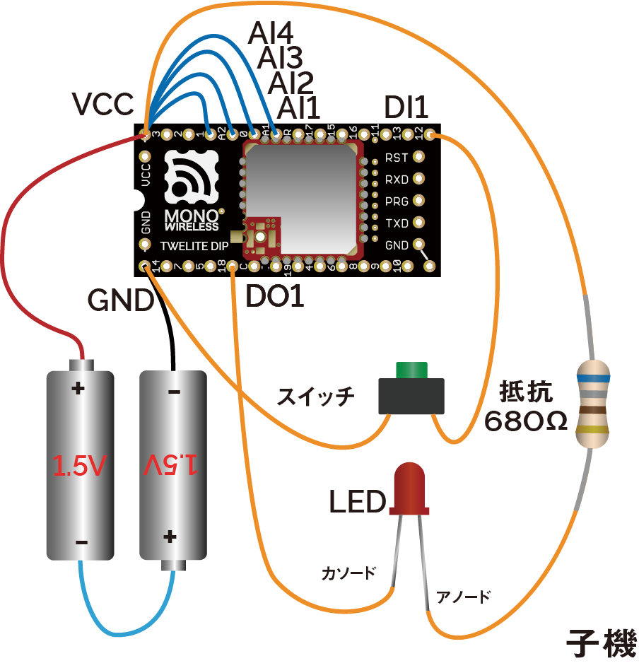
Child Wiring
In the above example, only DI1 and DO1 are used, but there are a total of 4 ports. Other ports can be used similarly.
Installing a Repeater
By placing a unit configured as a Repeater between the Parent and Child, communication distance can be extended. Up to 3 stages of repeaters can be used.
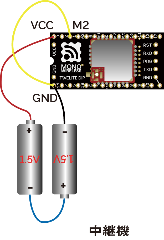
Repeater Wiring
Connect M2 to GND.