Products Used
 |  |
|---|---|
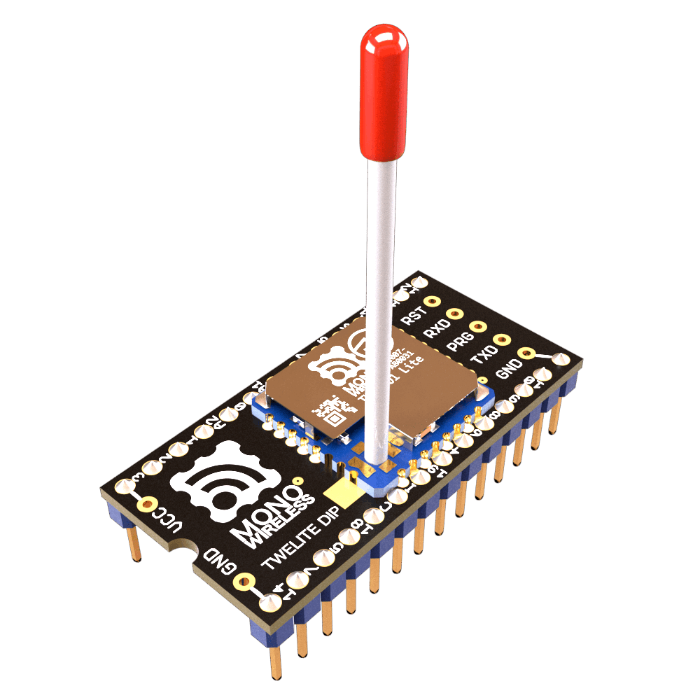
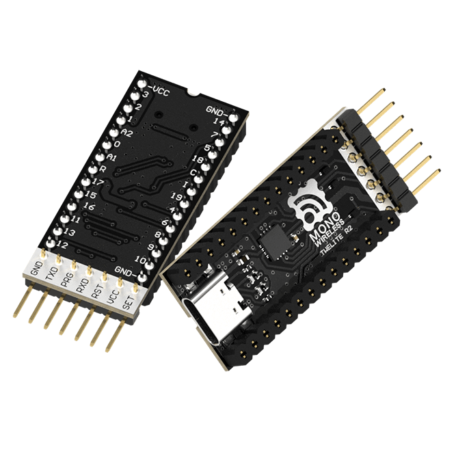
| TWELITE DIP | TWELITE R2 |
| TWELITE Parent/Child | USB Adapter |
| Extremely Simple! Standard App | - |
| 2 units | 1 unit |
Remote Control App
Write the TWELITE firmware to the Remote Control App (App_IO), which is specialized for digital signal transmission. While the Extremely Simple! Standard App supports digital signal transmission, its I/O is limited to 4 lines. The Remote Control App expands the number of I/O and allows you to switch their combinations.
Writing the Firmware
Write the firmware to all Parent, Child, and other devices as follows:
- Install the TWELITE STAGE SDK and launch the TWELITE STAGE App
- Select the connected device from Serial Port Selection
- From the Main Menu, select 2: Firmware Write
- Select 1: Select from BIN and choose
App_IO... - Press
Enterseveral times until writing is complete
With the default settings, after a successful write, the device will switch to the following Interactive Mode screen:
--- CONFIG/APP_IO V1-03-2/SID=0x86300001/LID=0x00 ---
 a: set Application ID (0x67720107)
 i: set Device ID (--)
 c: set Channels (16)
 x: set Tx Power (3)
 t: set mode4 sleep dur (1000ms)
 y: set mode7 sleep dur (0s)
 f: set mode3 fps (16)
 d: set hold mask (000000000000)
 D: set hold dur (1000ms)
 o: set Option Bits (0x00000000)
 b: set UART baud (38400)
 p: set UART parity (N)
 C: set crypt mode (0)
 K: set crypt key []
---
 S: save Configuration
 R: reset to Defaults
Try It Out
By default, the Remote Control App is configured for one-way transmission, with the Child having 12 digital input ports and the Parent having 12 digital output ports. Let’s do the wiring.
| Name | Child | Parent | Standard | DIP # |
|---|---|---|---|---|
I1/O5 | I1 | O5 | DI1 | 15 |
I2/O6 | I2 | O6 | DI2 | 16 |
I3/O7 | I3 | O7 | DI3 | 17 |
I4/O8 | I4 | O8 | DI4 | 18 |
I5/O1 | I5 | O1 | DO1 | 5 |
I6/O2 | I6 | O2 | DO2 | 8 |
I7/O3 | I7 | O3 | DO3 | 9 |
I8/O4 | I8 | O4 | DO4 | 12 |
I9/O9 | I9 | O9 | SCL | 2 |
I10/O10 | I10 | O10 | SDA | 19 |
I11/O11 | I11 | O11 | PWM1 | 4 |
I12/O12 | I12 | O12 | PWM4 | 11 |
Parent Wiring
In the default state, the Parent can receive up to 12 digital signals.
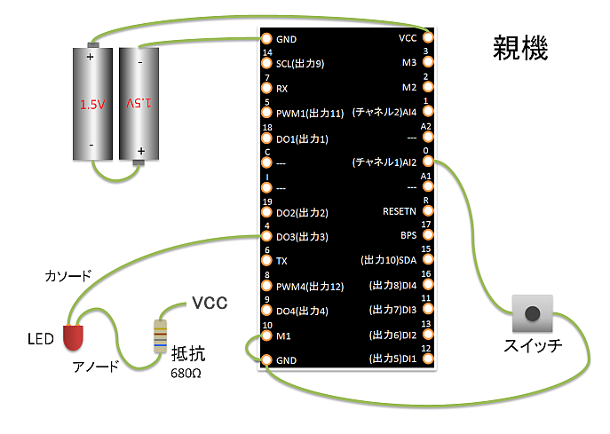
Parent wiring diagram
In the diagram above, DIP pin 9 (O3) is used as an output, but other Ox pins can be used similarly. To test the channel override function, which is not available in the Extremely Simple! Standard App, a tactile switch is connected to DIP pin 23 (C1).
Child Wiring
In the default state, the Child can send up to 12 digital signals.
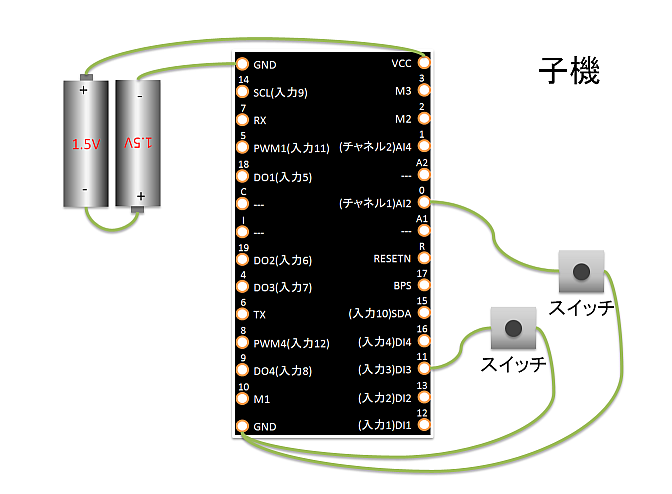
Child wiring diagram
In the diagram above, DIP pin 17 (I3) is used as an input, but other Ix pins can be used similarly. Similarly, to test the channel override function, a tactile switch is connected to DIP pin 23 (C1).
Operation Check
- Press and release the button connected to the Child’s
I3.- The LED connected to the Parent’s
O3will turn on and off accordingly.
- The LED connected to the Parent’s
- While pressing the button connected to the Child’s
C1, press and release the button onI3.- Communication will not occur because the Child’s frequency channel is temporarily overridden.
- While pressing the buttons connected to both the Parent’s and Child’s
C1, press and release the button connected to the Child’sI3.- Communication will resume because both Parent and Child frequency channels are overridden to match.
The C1/C2 pins override the frequency channel as follows:
C2 | C1 | Frequency Channel |
|---|---|---|
| Not connected | Not connected | Default (initial value is 16) |
| Not connected | GND | 12 |
GND | Not connected | 21 |
GND | GND | 25 |
If you have extra buttons and LEDs, try increasing the number of I/O.
With 12 channels available, you could use, for example, a 7-segment LED.
Using Advanced Features
Let’s try changing settings in Interactive Mode for the following scenarios:
- Change the I/O assignment so both Child and Parent have 6 inputs and 6 outputs each
- Reflect the Child’s input to the Parent as quickly as possible
- Restore output signals if packets are lost
- Use the Child as a low-power remote
- Use the Child as a low-power remote supporting continuous transmission by long press
Assigning 6 Inputs and 6 Outputs to Both Child and Parent
By changing the value of Option Bits in Interactive Mode, you can select the I/O assignment from the following options:
| Child Input | Child Output | Parent Input | Parent Output | Note |
|---|---|---|---|---|
| 12 | 0 | 0 | 12 | Default |
| 8 | 4 | 4 | 8 | Option Bit 0x00001000 |
| 6 | 6 | 6 | 6 | Option Bit 0x00002000 |
| 0 | 12 | 12 | 0 | Option Bit 0x00003000 |
Let’s set both devices to have 6 inputs and 6 outputs.
- Launch the TWELITE STAGE App
- Select the connected device from Serial Port Selection
- From the Main Menu, select 3: Interactive Mode
- Press
Enterand confirm that the settings list is shown - Enter
o(lowercase), input the Option Bits value00002000, and pressEnter - Enter
S(uppercase) to save, then pressESCto exit
Now, the assignment with both Child and Parent having 6 inputs and 6 outputs will be as follows:
| Name | Child | Parent | Standard | DIP # |
|---|---|---|---|---|
I1/O5 | I1 | I1 | DI1 | 15 |
I2/O6 | I2 | I2 | DI2 | 16 |
I3/O7 | I3 | I3 | DI3 | 17 |
I4/O8 | I4 | I4 | DI4 | 18 |
I5/O1 | O1 | O1 | DO1 | 5 |
I6/O2 | O2 | O2 | DO2 | 8 |
I7/O3 | O3 | O3 | DO3 | 9 |
I8/O4 | O4 | O4 | DO4 | 12 |
I9/O9 | O5 | I5 | SCL | 2 |
I10/O10 | O6 | I6 | SDA | 19 |
I11/O11 | I5 | O5 | PWM1 | 4 |
I12/O12 | I6 | O6 | PWM4 | 11 |
Reflecting Child Input to Parent Output as Fast as Possible
When using the Child’s continuous mode, there is usually a delay of about 30-70ms from Child input to Parent output. If you need faster response, set Option Bits 0x00000001: Low Latency Mode via Interactive Mode.
Child Settings
- Launch the TWELITE STAGE App
- Select the connected device from Serial Port Selection
- From the Main Menu, select 3: Interactive Mode
- Press
Enterand confirm that the settings list is shown - Enter
o(lowercase), input the Option Bits value00000001, and pressEnter - Enter
S(uppercase) to save, then pressESCto exit
If multiple inputs change almost simultaneously, they are transmitted in order, which may cause delays for subsequent inputs.
Also, if input chattering occurs, it may be reflected directly to the output.
When Low Latency Mode is applied to the Child’s intermittent mode, its behavior differs from continuous mode:
- Upon wake-up by interrupt, only the value of the corresponding interrupt port is sent
- If a port is used as an interrupt wake-up pin, the states of other ports cannot be read simultaneously upon wake-up
- When returning from sleep, the IO port state is determined in 1/4 the usual time
Restoring Output Signals When Packets Are Lost
If radio communication is interrupted while any input is held Low, the output will remain Low even if the actual input returns to High.
To return the signal to its original state when packets are lost, enable Remote Long Press Mode. In this mode, after the sending side input changes, the signal is sent continuously for a while. On the receiving side, if no packet indicating a Low state is received for a certain period, the output times out and returns to High.
Child Settings
- Set
M1/M2/M3open, and set Child: Continuous Mode - Launch the TWELITE STAGE App
- Select the connected device from Serial Port Selection
- From the Main Menu, select 3: Interactive Mode
- Press
Enterand confirm that the settings list is shown - Enter
o(lowercase), input the Option Bits value00000100and pressEnter - Enter
d(lowercase), input the hold/long-press target (for example,000000001010forI2andI4), and pressEnter - Enter
D(uppercase), input the hold/long-press time (the duration to continue sending after all inputs return from Low to High), and pressEnter - Enter
S(uppercase) to save, then pressESCto exit
Parent Settings
- Set
M1/M2/M3open, and set Child: Continuous Mode - Launch the TWELITE STAGE App
- Select the connected device from Serial Port Selection
- From the Main Menu, select 3: Interactive Mode
- Press
Enterand confirm that the settings list is shown - Enter
o(lowercase), input the Option Bits value00000100and pressEnter - Enter
d(lowercase), input the hold/long-press target (for example,000000001010forO2andO4), and pressEnter - Enter
D(uppercase), input the hold/long-press time (the duration to return the output from Low to High after signal loss), and pressEnter - Enter
S(uppercase) to save, then pressESCto exit
Using the Child as a Low Power Remote
If the Child is battery-powered, intermittent mode, which alternates sleep and wake, is effective. By combining Low Latency Mode and Hold Mode, the Parent’s output can be maintained for a set time when the Child’s button is pressed.
Child Settings
- Connect
M1/M2/M3toGNDand set Child: Intermittent 10s Mode - Launch the TWELITE STAGE App
- Select the connected device from Serial Port Selection
- From the Main Menu, select 3: Interactive Mode
- Press
Enterand confirm that the settings list is shown - Enter
o(lowercase), input the Option Bits value00000001and pressEnter - Enter
S(uppercase) to save, then pressESCto exit
Parent Settings
- Set
M1/M2/M3open, and set Child: Continuous Mode - Launch the TWELITE STAGE App
- Select the connected device from Serial Port Selection
- From the Main Menu, select 3: Interactive Mode
- Press
Enterand confirm that the settings list is shown - Enter
d(lowercase), input the hold/long-press target (for example,000000001010forO2andO4), and pressEnter - Enter
D(uppercase), input the hold/long-press time (hold time), and pressEnter - Enter
S(uppercase) to save, then pressESCto exit
Using the Child as a Low Power Remote with Long Press
If the Child is battery-powered, intermittent mode is effective. By combining Low Latency Mode and Remote Long Press Mode, the Child can continuously send data to the Parent while a button is held. Even after the button is released, the Child continues sending for a set period, and on the Parent side, if radio packets indicating the button remains pressed are lost for a set period, the output returns to its original state. This ensures reliable delivery of the Child’s input even in low-power operation.
Child Settings
- Connect
M1/M2/M3toGNDand set Child: Intermittent 10s Mode - Launch the TWELITE STAGE App
- Select the connected device from Serial Port Selection
- From the Main Menu, select 3: Interactive Mode
- Press
Enterand confirm that the settings list is shown - Enter
o(lowercase), input the Option Bits value00000103(00000100+00000001+00000002), and pressEnter - Enter
d(lowercase), input the hold/long-press target (for example,000000001010forI2andI4), and pressEnter - Enter
D(uppercase), input the hold/long-press time (the duration to continue sending after all inputs return from Low to High), and pressEnter - Enter
S(uppercase) to save, then pressESCto exit
Parent Settings
- Set
M1/M2/M3open, and set Child: Continuous Mode - Launch the TWELITE STAGE App
- Select the connected device from Serial Port Selection
- From the Main Menu, select 3: Interactive Mode
- Press
Enterand confirm that the settings list is shown - Enter
o(lowercase), input the Option Bits value00000100and pressEnter - Enter
d(lowercase), input the hold/long-press target (for example,000000001010forO2andO4), and pressEnter - Enter
D(uppercase), input the hold/long-press time (the duration to return the output from Low to High after signal loss), and pressEnter - Enter
S(uppercase) to save, then pressESCto exit