Customization via Interactive Mode
What is Interactive Mode
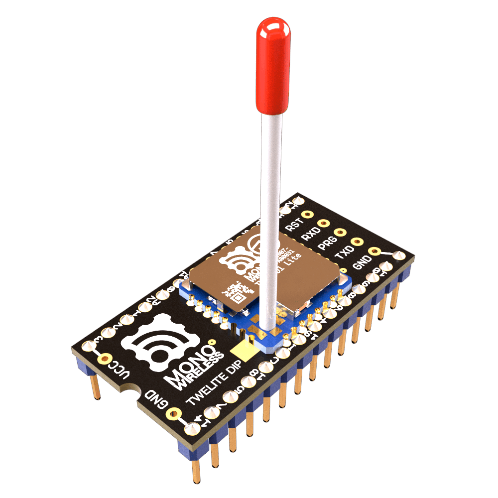
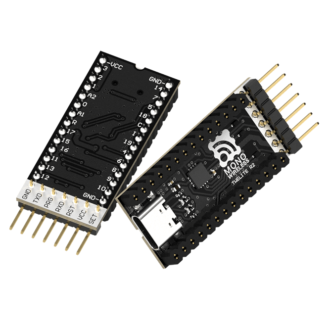
Interactive Mode is a mode used when connecting the TWELITE series to a PC for configuration. By connecting the TWELITE series to a PC via a USB adapter TWELITE R series, you can change various parameters through UART communication.
We recommend using the TWELITE STAGE app. The TWELITE STAGE app is a tool that includes functions for firmware configuration and writing, as well as features to evaluate communication with the parent device. The TWELITE STAGE app is included in the TWELITE STAGE SDK.
For more details about the TWELITE STAGE app, please refer to the TWELITE APPS Manual.
Custom Examples
Below are customization examples of TWELITE DIP for different purposes.
Please select and try the ones you are interested in.
- Network Grouping
- Prepare two pairs of parent and child devices and operate them independently
- Using Low Latency Mode
- Prepare a pair of parent and child devices and reduce delay in transmission from
DIxtoDOx
- Prepare a pair of parent and child devices and reduce delay in transmission from
- Transmit Only When Button is Pressed
- Prepare a pair of parent and child devices and configure so that transmission occurs only when the parent’s button is pressed
Network Grouping
By default, all TWELITE DIP devices can communicate with each other. When you prepare two pairs of parent and child devices, the inputs of the parent are reflected to both children, and the inputs of the children are reflected to both parents.
Using Interactive Mode, change the Application ID and frequency channel to separate the two pairs so they can be used independently at the same time.
Products Used
 |  |
|---|---|
| TWELITE DIP | TWELITE R2 |
| TWELITE Parent / Child | USB Adapter |
| Extremely Simple! Standard App | - |
| 4 units | 1 unit |
Customization Details
Set the Interactive Mode values as follows to divide the two pairs into Group A and Group B.
- Group A
- Parent / Child
- Application ID:
0xAAAAAAAA - Frequency Channel:
11
- Application ID:
- Parent / Child
- Group B
- Parent / Child
- Application ID:
0xBBBBBBBB - Frequency Channel:
26
- Application ID:
- Parent / Child
Customization Procedure
- Insert the TWELITE DIP into the TWELITE R2 and connect it to the PC using a USB-C cable
- Launch the TWELITE STAGE app and select the target TWELITE R2 from Serial Port Selection
- From the Main Menu, select “3: Interactive Mode”
- Press uppercase
Rto reset settings to default - Press
a, inputAAAAAAAA/BBBBBBBB, and pressEnter - Press
c, input11/26, and pressEnter - Press uppercase
Sto apply settings (TWELITE will reset) - Press
ESCseveral times to return to the Main Menu and disconnect the TWELITE R2 USB-C cable - Remove the TWELITE DIP and insert it into a breadboard or connect it to the circuit
Operation Check
Wire both Group A and Group B as in the “Try It Out First” One-Way Digital Signal Example, connecting a switch to the parent and an LED to the child.
- Pressing the switch on Group A’s parent lights only Group A’s child LED
- Pressing the switch on Group B’s parent lights only Group B’s child LED
Change the Application ID of Group B’s child to 0xAAAAAAAA and the frequency channel to 11.
- Pressing the switch on Group A’s parent lights LEDs on both children
Using Low Latency Mode
By default, there is a delay of about 30-70ms from when the source DIx changes until it is reflected on the destination DOx. This delay exists due to processing to avoid chattering and wireless packet interference.
Low Latency Mode shortens this delay to about 3-10ms by simplifying these processes.
Enable low latency mode on the transmitting device (parent) via Interactive Mode.
Low latency mode is useful in cases such as:
- When the hardware has no concern about chattering
- When input states change rapidly
Products Used
| |
|---|---|
| TWELITE DIP | TWELITE R2 |
| TWELITE Parent / Child | USB Adapter |
| Extremely Simple! Standard App | - |
| 2 units | 1 unit |
Customization Details
Set the Interactive Mode values as follows to enable low latency mode on the transmitting device (parent).
- Parent
- Child: No change
Customization Procedure
- Insert the TWELITE DIP into the TWELITE R2 and connect it to the PC using a USB-C cable
- Launch the TWELITE STAGE app and select the target TWELITE R2 from Serial Port Selection
- From the Main Menu, select “3: Interactive Mode”
- Press uppercase
Rto reset settings to default - Press
o, input00000001, and pressEnter - Press uppercase
Sto apply settings (TWELITE will reset) - Press
ESCseveral times to return to the Main Menu and disconnect the TWELITE R2 USB-C cable - Remove the TWELITE DIP and insert it into a breadboard or connect it to the circuit
Operation Check
Wire the parent and child as in the “Try It Out First” One-Way Digital Signal Example, connecting a switch to the parent and an LED to the child.
- Pressing the parent’s switch lights the child’s LED
- The operation is the same as the default state, but you might notice slightly improved response
- Connect an oscilloscope to the parent’s
DO1and child’sDI1to compare and confirm the effect
Transmit Only When Button is Pressed
By default, transmission occurs when the input state changes and also once every second.
In this case, for example, if the transmitting device’s button is held down and the power is cut, the output on the receiving side remains.
The Transmit Only When Button is Pressed setting causes the transmitting device to repeatedly send when DIx is Low, and continue sending for one second after transitioning to High. If the receiving device’s DOx is set Low and reception stops, it returns to High.
Change the setting via Interactive Mode to transmit only when the button is pressed.
DIx is Low, increasing the number of transmitters on the same frequency channel is not recommended. Apply this option only for 1:1 communication.Products Used
| |
|---|---|
| TWELITE DIP | TWELITE R2 |
| TWELITE Parent / Child | USB Adapter |
| Extremely Simple! Standard App | - |
| 2 units | 1 unit |
Customization Details
Set the Interactive Mode values as follows to change the behavior of digital input/output on the transmitting device (parent) and receiving device (child).
- Parent / Child
- Option Bits:
0x00000100
- Option Bits:
Customization Procedure
- Insert the TWELITE DIP into the TWELITE R2 and connect it to the PC using a USB-C cable
- Launch the TWELITE STAGE app and select the target TWELITE R2 from Serial Port Selection
- From the Main Menu, select “3: Interactive Mode”
- Press uppercase
Rto reset settings to default - Press
o, input00000100, and pressEnter - Press uppercase
Sto apply settings (TWELITE will reset) - Press
ESCseveral times to return to the Main Menu and disconnect the TWELITE R2 USB-C cable - Remove the TWELITE DIP and insert it into a breadboard or connect it to the circuit
Operation Check
Wire the parent and child as in the “Try It Out First” One-Way Digital Signal Example, connecting a switch to the parent and an LED to the child.
- Pressing the parent’s switch lights the child’s LED
- If the parent’s switch is held down and the power supply is cut off, the child’s LED turns off (it does not turn off in the default state)