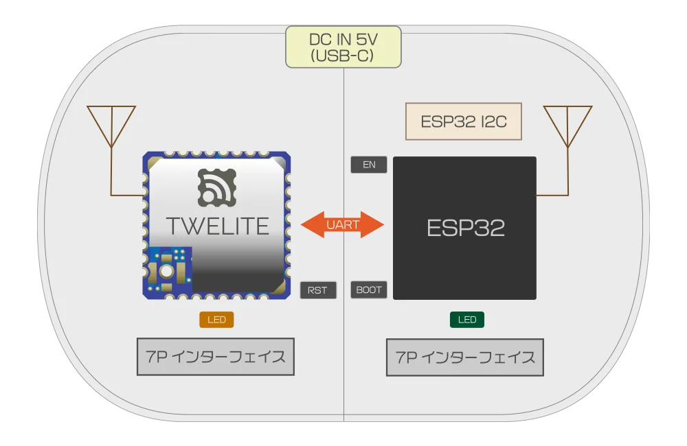
The wireless LAN gateway TWELITE SPOT is a product that combines the low-power wireless microcontroller module TWELITE with the wireless LAN microcontroller module ESP32. By developing firmware for the ESP32, you can integrate the TWELITE network with Wi-Fi networks.
For product specifications, please refer to the Datasheet.
Expanding Possibilities with TWELITE and ESP32
TWELITE SPOT is a product that combines the compact, low-power, and pairing-free TWELITE series—which allows many devices to be used simultaneously—with the wireless LAN microcontroller module ESP32.
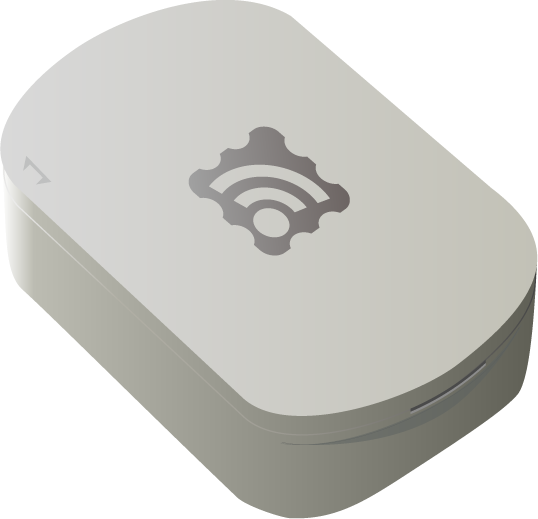
Appearance
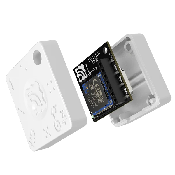
Internal Structure
For customers who frequently use the TWELITE series
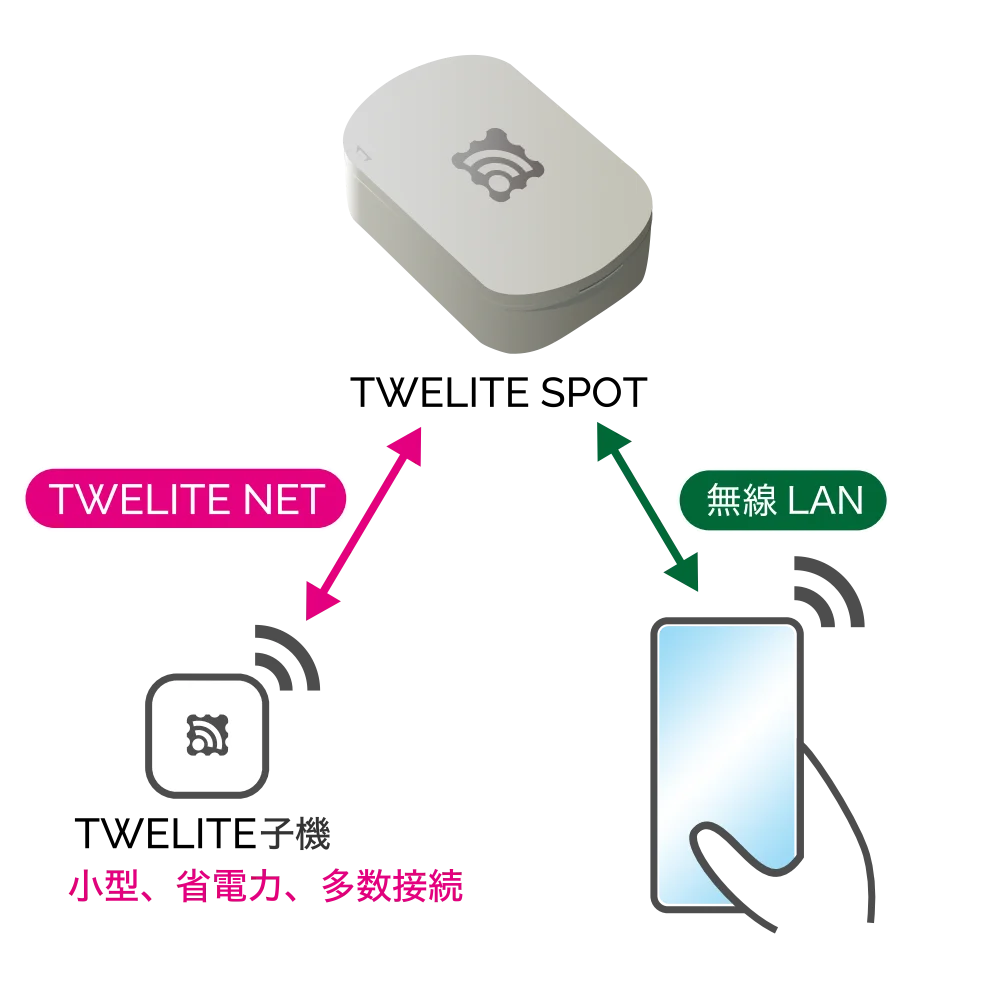
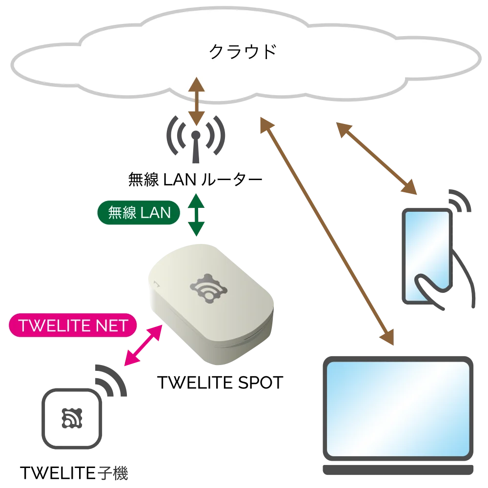
Share data from TWELITE Child devices within the LAN
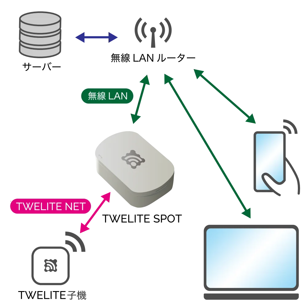
Use data from TWELITE Child devices within the LAN
Use data from TWELITE Child devices in the cloud
Local Server
The ESP32 is used as a server. For example, you can display acceleration data measured by a TWELITE CUE on a smartphone or operate the output ports of a TWELITE DIP from a smartphone.
The ESP32 connects to the LAN. For example, data sent from TWELITE ARIA devices installed throughout a building can be received by TWELITE SPOT devices on each floor, aggregating temperature and humidity data from all floors on a server within the LAN.
The ESP32 connects to the Internet. For example, by attaching a TWELITE CUE and a magnet to a door, you can detect on the cloud whether the door remains open based on the acquired door open/close status.
Development with Arduino IDE and Dedicated Library
To build a system using TWELITE SPOT, you need to develop firmware for the ESP32.
Arduino IDE can be used for firmware development on the ESP32.
Development using Arduino IDE
There is a vast amount of information online about firmware development using Arduino IDE.
For example, try searching for esp32 arduino.
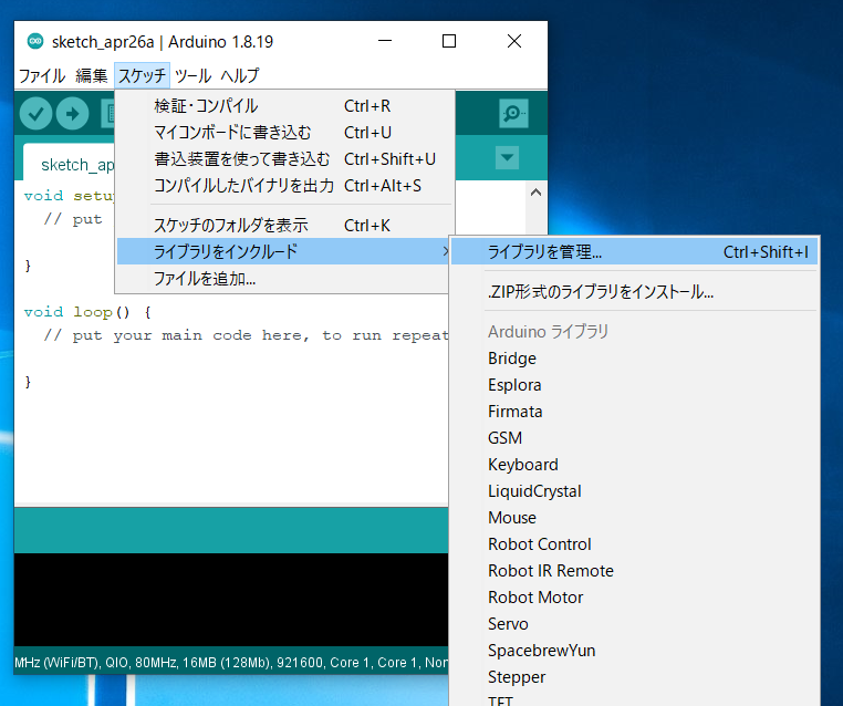
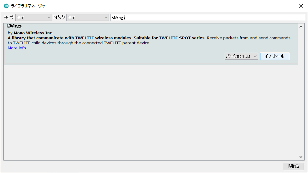
The MWings library, distributed via the Arduino Library Manager, makes it easy to receive packets from TWELITE Child devices and send commands to them.
The start guide uses third-party open-source software.
We cannot provide detailed instructions on the use of third-party software. We also assume no responsibility for any damages resulting from the use of third-party software.
1 - Getting Started
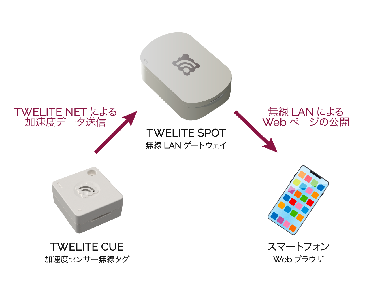
Display acceleration data from TWELITE CUE on your smartphone using TWELITE SPOT
TWELITE SPOT can host dynamic pages on a web server running on ESP32, distributing data received from TWELITE Child devices within the network.
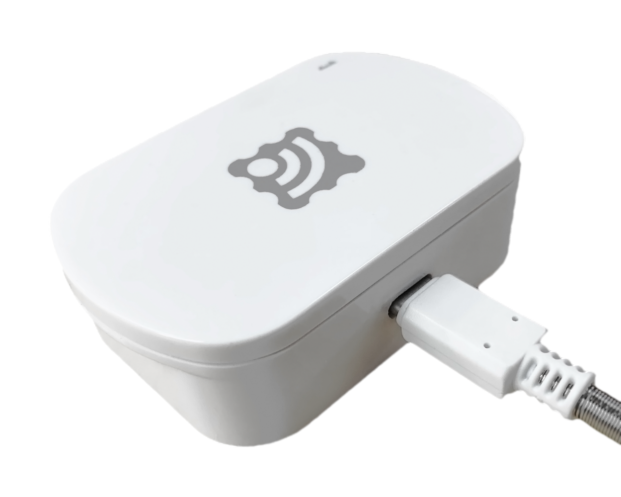
Connect the USB-C cable to the side of TWELITE SPOT and supply power from the USB AC adapter.
Connecting USB Power
2. Power On TWELITE CUE ⚡
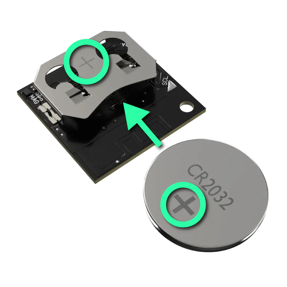
Insert a CR2032 coin battery into TWELITE CUE. It will start operating immediately.
Inserting Coin Battery
When TWELITE CUE starts normally, the LED on the side with the logo will blink.
TWELITE CUE cannot communicate with TWELITE SPOT unless it is in the default factory settings.
If you have changed the settings of TWELITE CUE, please change the settings again to return it to factory default.
3. Connect Your Smartphone 📱
Connect your smartphone to the Wi-Fi network TWELITE SPOT (XXXX) from the Wi-Fi settings.
The password is twelitespot. The XXXX in the SSID is a device-specific identifier.
4. Open a Web Browser 🌐
Open a web browser on your smartphone and access spot.local.
If you cannot connect, try accessing 192.168.1.1.
If that still does not work, try accessing http://192.168.1.1/.
You will see a screen like the following.
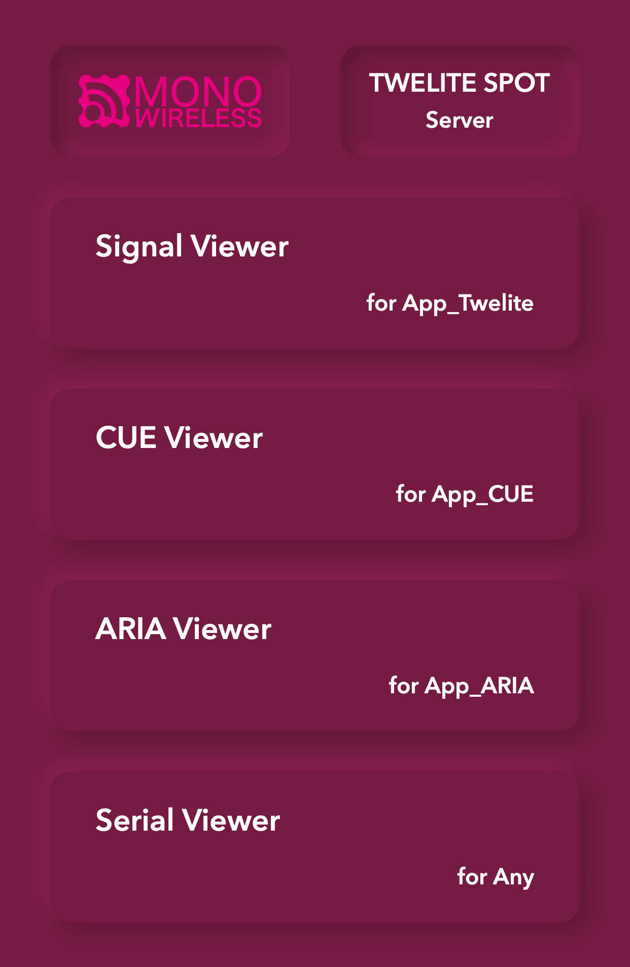
Top Page
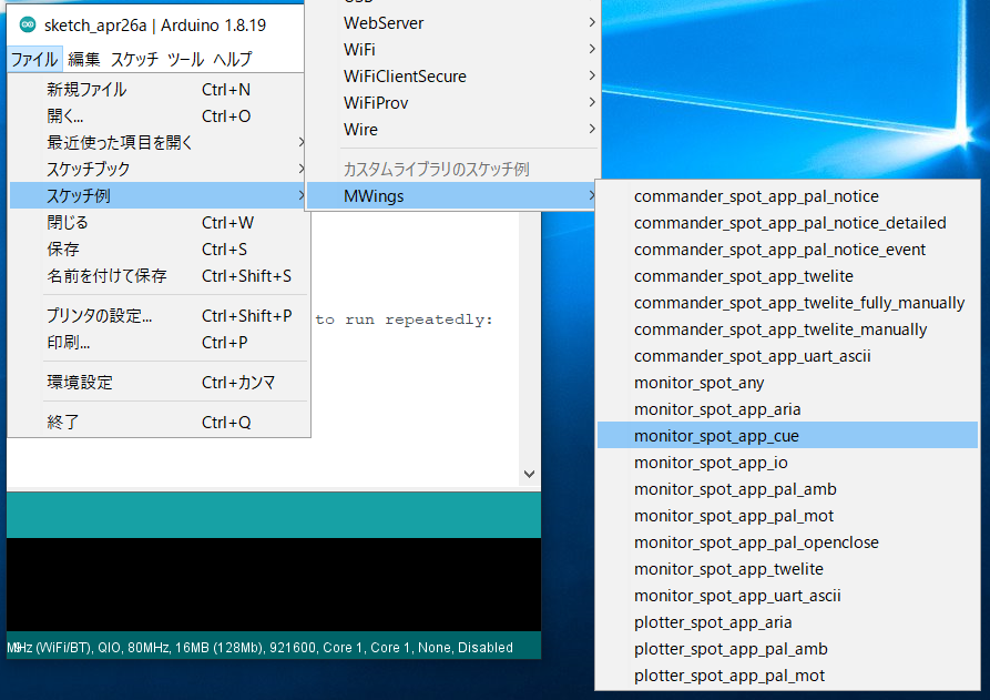
5. Open the CUE Viewer 📈
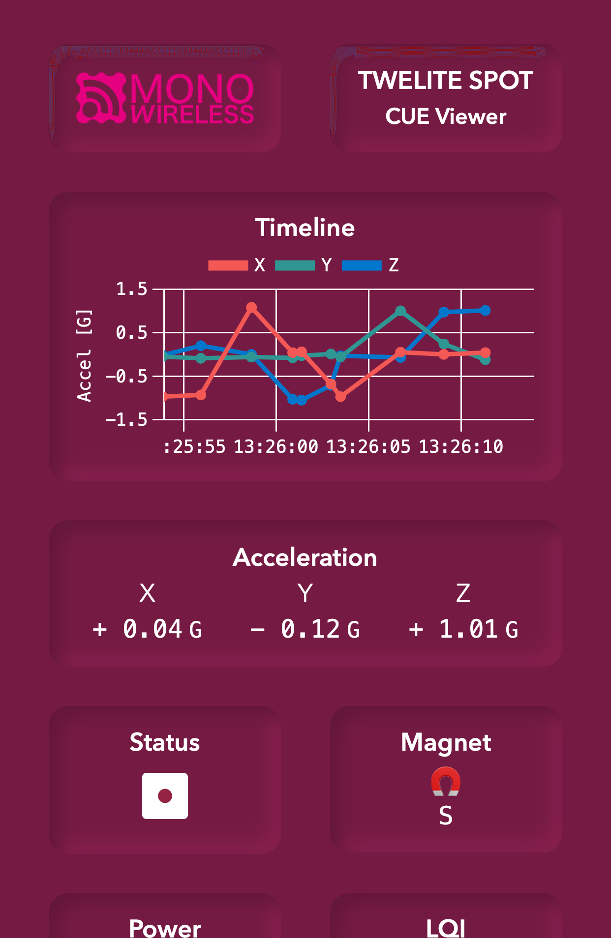
Tap on CUE Viewer to open the CUE viewer screen.
You will see a screen like the following.
Try changing the orientation of TWELITE CUE.
The CUE viewer displays the number on the dice printed on TWELITE CUE.
You have confirmed the operation of TWELITE SPOT using TWELITE NET and wireless LAN!
For more details about the features, please refer to the TWELITE SPOT Manual.
2 - Basics of Firmware Development with ESP32
Try Hello World on ESP32 for TWELITE SPOT firmware development
ESP32 can build a system using wireless LAN on its own. For example, you can display data on a hosted web page, send data to a server within the LAN via WebSocket, or send REST API requests to cloud services.
TWELITE SPOT is a product that combines this ESP32 with TWELITE, enabling the use of many small, low-power wireless tags.
First, let’s try Hello World to learn the basics of firmware development for ESP32.
We will set up the development environment, create and write the Hello World sketch, and verify its operation.
This content also serves as an operation check for TWELITE SPOT. Even if you have experience developing firmware for ESP32 using Arduino IDE, please review the following.
TWELITE SPOT is equipped with both TWELITE and ESP32, but usually, you only develop firmware for the latter. For TWELITE firmware, please use the pre-installed Parent and Repeater applications.
Although the latest Arduino IDE 2.x can also write sketches similarly to Arduino IDE 1.x, as of May 2023, the Java-based plugin does not work, so the Legacy IDE is recommended.
2. Install the Toolchain 🚚
If you have not installed Arduino core for the ESP32 in Arduino IDE, add the following URL to the Board Manager URLs and install the esp32 board definition.
From here, the content is specific to TWELITE SPOT.
Configure Arduino core for the ESP32 to match TWELITE SPOT.
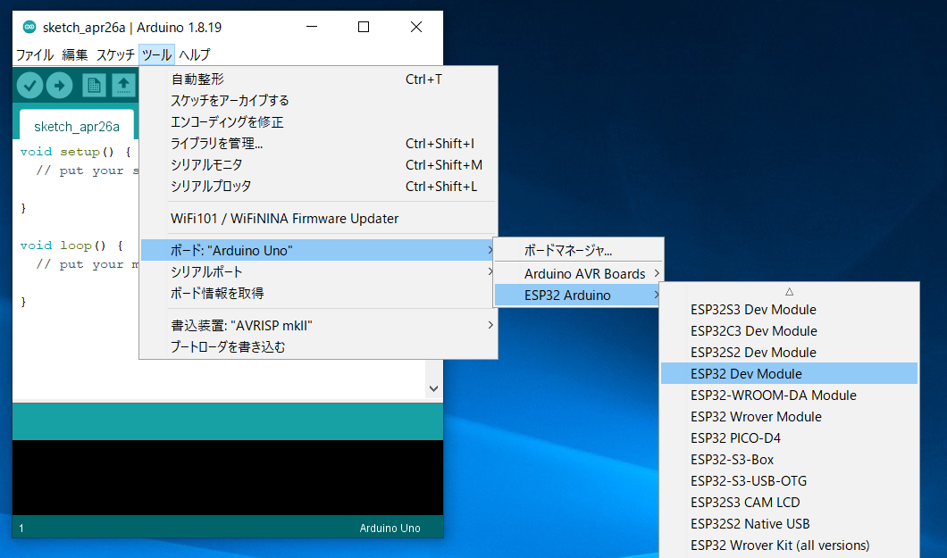
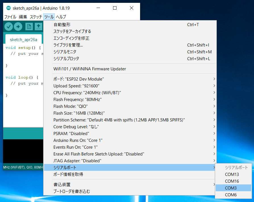
Select the Board Type
From the toolbar, select Tools -> Board -> ESP32 Arduino -> ESP32 Dev Module.
Location of ESP32 Dev Module
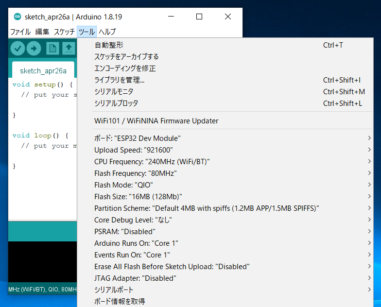
Configure Board Settings
Configure as shown in the figure below.
Settings after configuration
Change Flash size from 4MB (32Mb) to 16MB (128Mb).
Prepare TWELITE SPOT
1. Remove the Cover ⛏️
Remove the cover on the top of the TWELITE SPOT case.
Switches and connectors will be exposed.
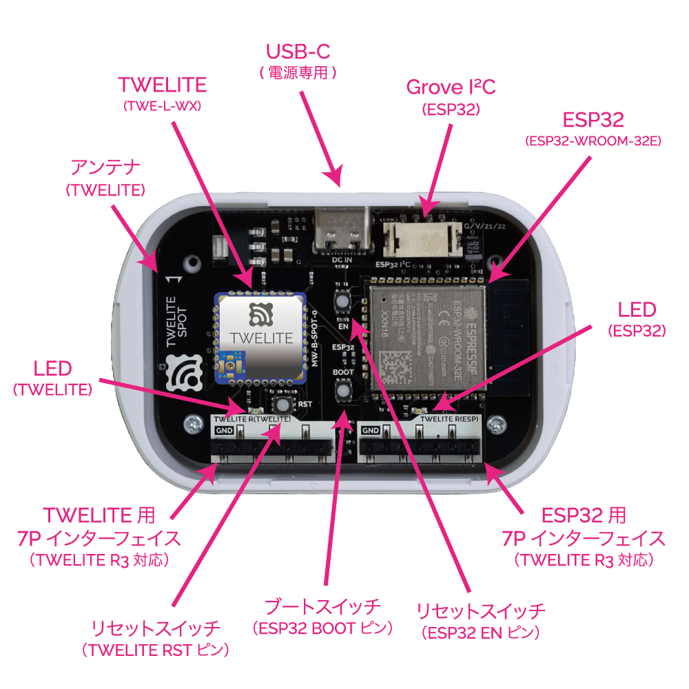
Names of each part
For details of each part, please see the datasheet.
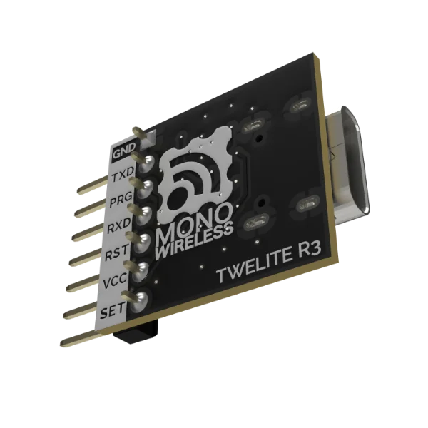
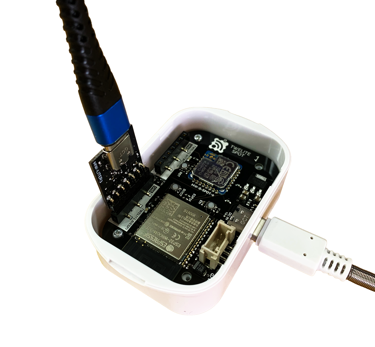
2. Connect TWELITE R3 / R2 🔌
Connect TWELITE R3 / R2 to the 7P interface for ESP32 (marked ESP32).
Connection example (ESP32)
Always connect TWELITE R3 / R2 to TWELITE SPOT in the same orientation as shown above. Connecting in the wrong orientation may damage TWELITE SPOT or TWELITE R3 / R2.
Tip 👉 Face the surface of TWELITE R3 / R2 towards the connection target.
The VCC pin of each 7P interface is not connected. Since TWELITE R series cannot supply power, you need to supply power from the USB-C connector on the side.
3. Connect USB-C Power ⚡
Supply 5V power to the USB-C connector on the side.
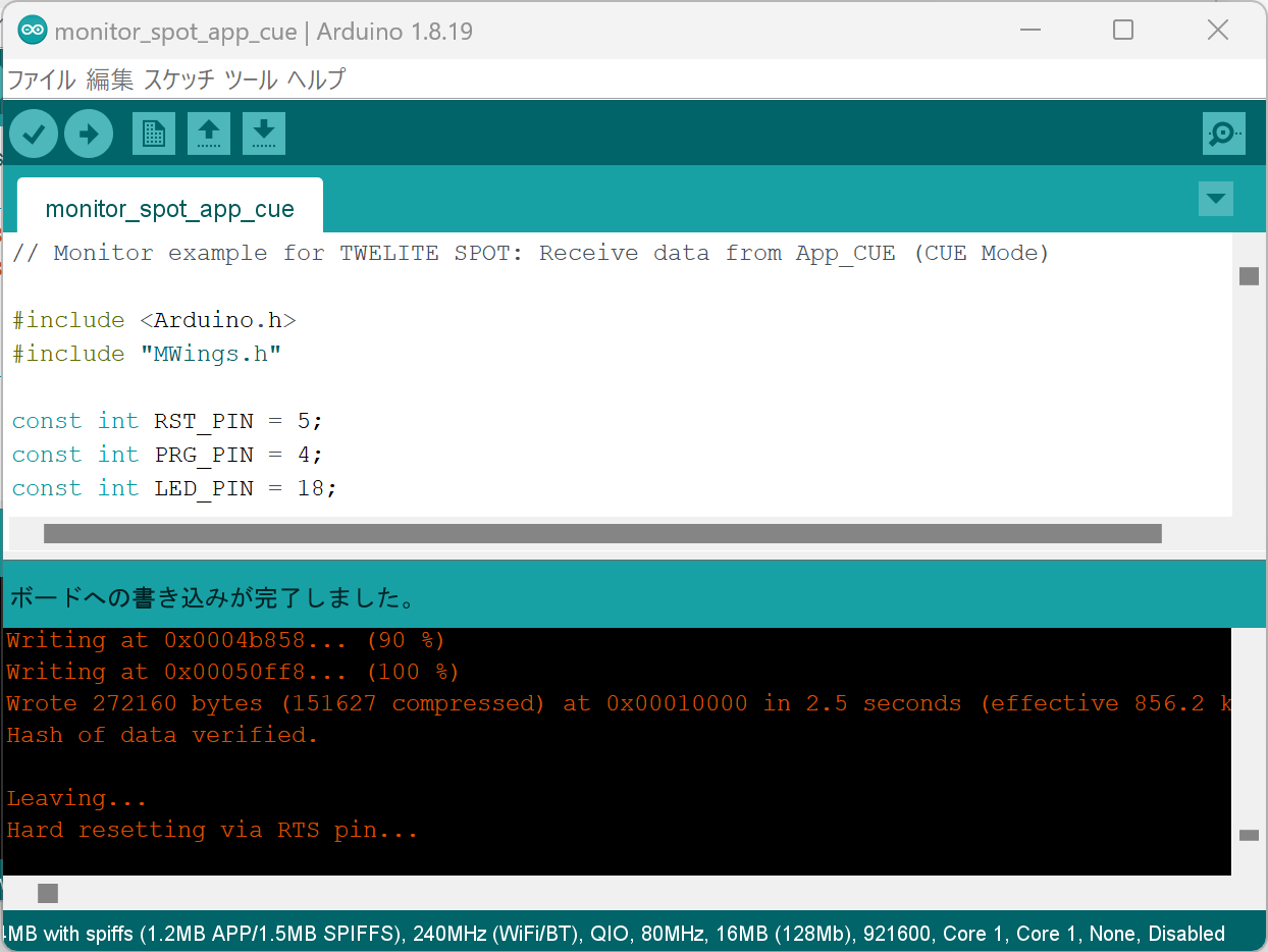
Run the Sketch
In Arduino, programs/projects are called sketches.
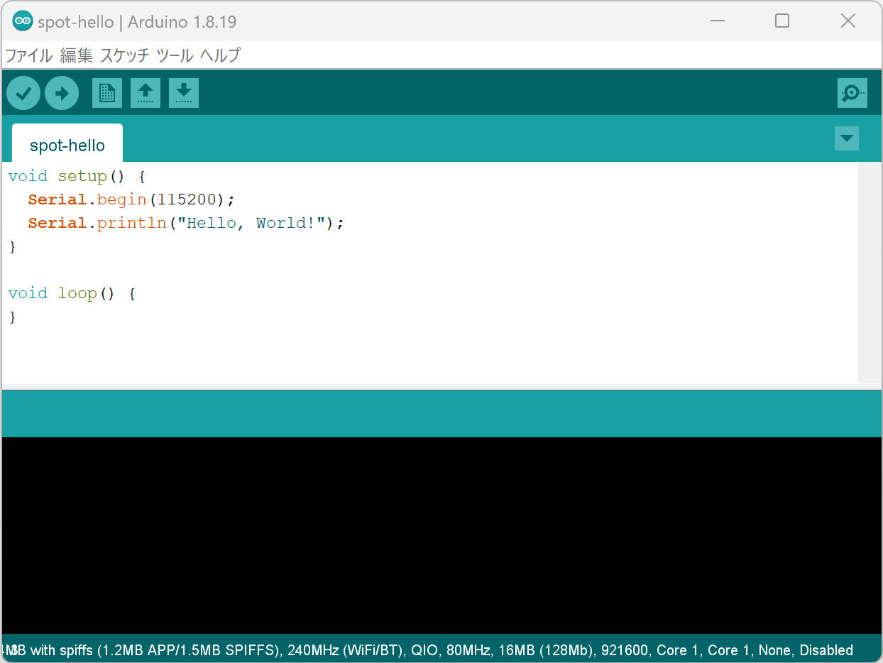
1. Create the Sketch 👨💻
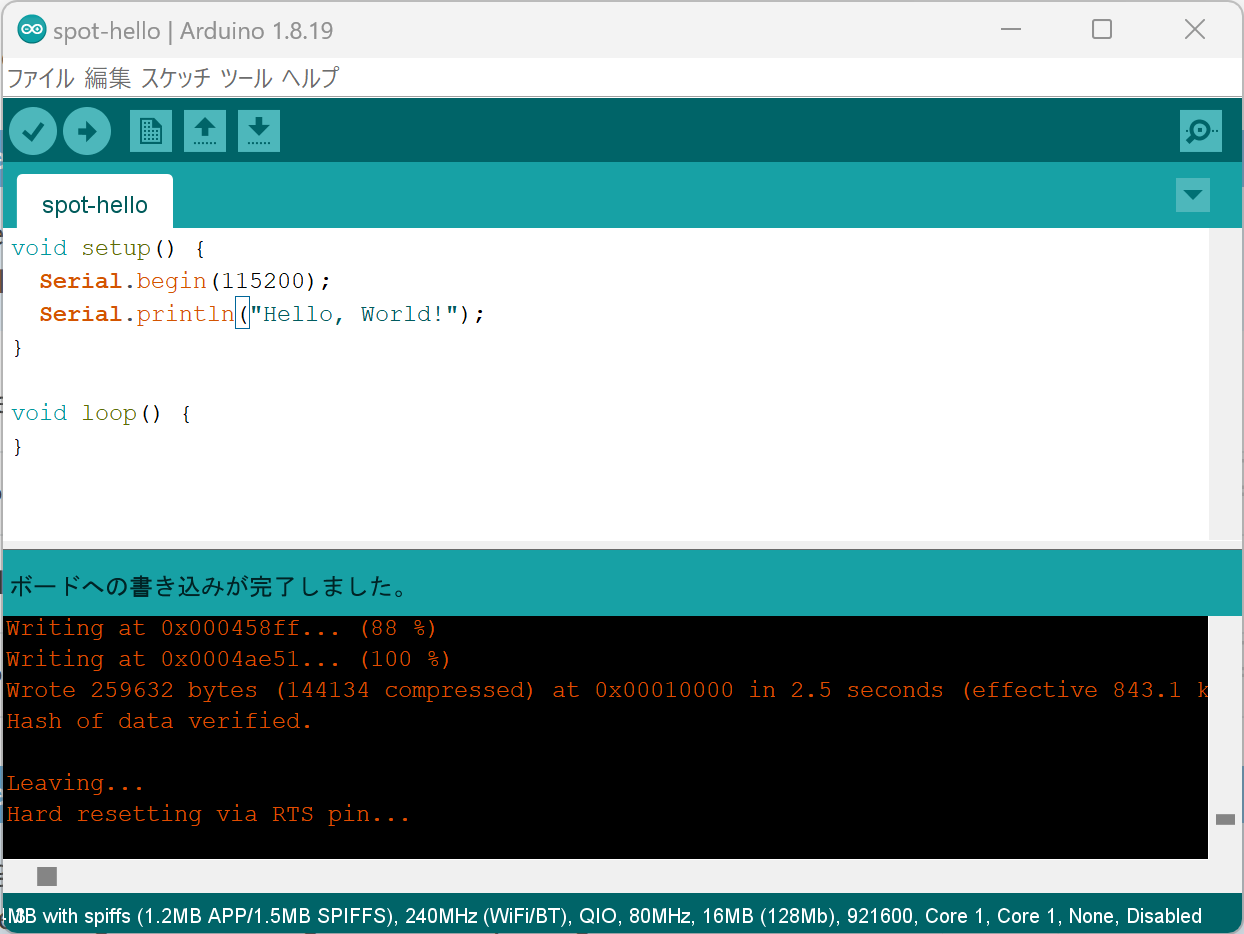
Create a Hello World sketch that outputs a string from ESP32 to the serial port and displays it on the Arduino IDE serial monitor.
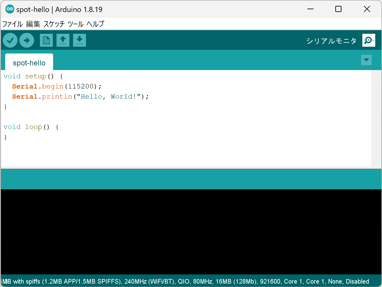
Click the Serial Monitor button at the top right of the Arduino IDE.
Serial Monitor Button at Top Right
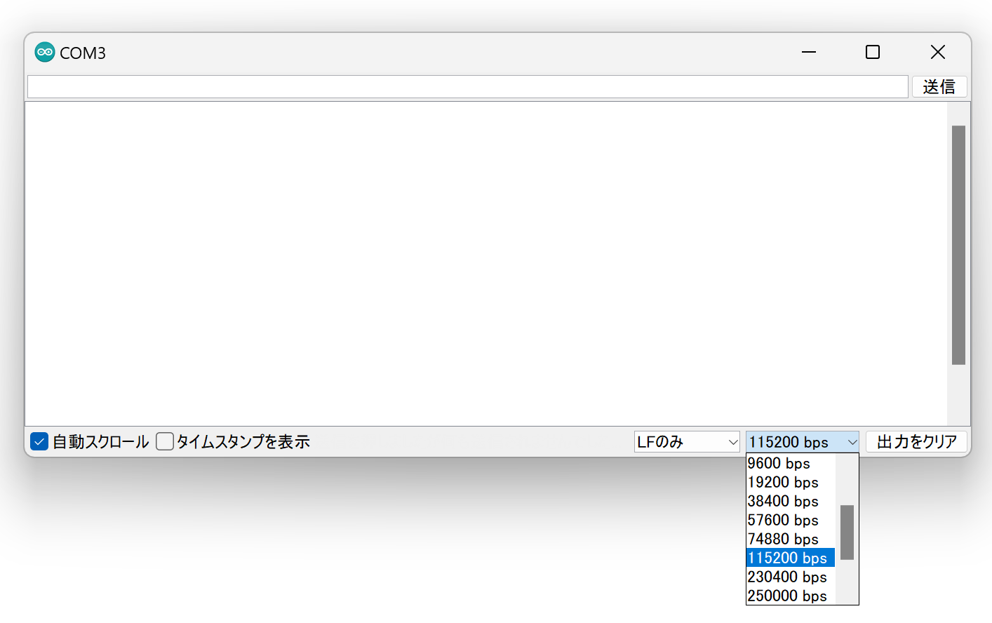
Configure
Set the serial monitor baud rate to 115200.
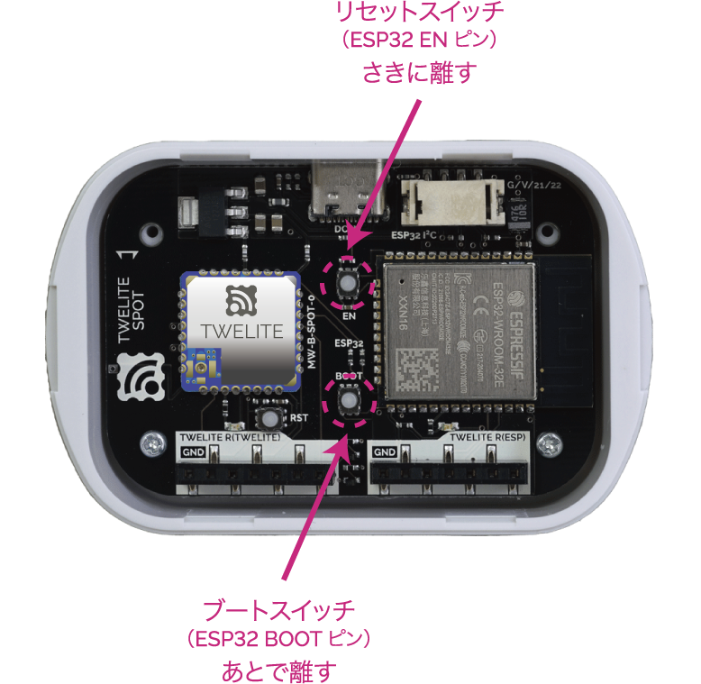
6. Restart ESP32 🚀
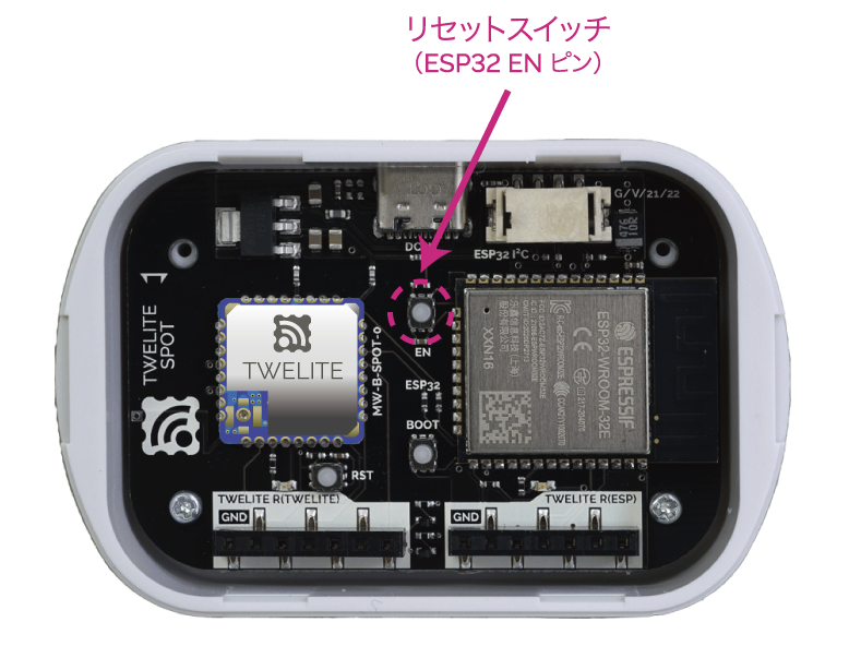
After writing is complete, press and release the ESP32 reset switch EN(RST) on the TWELITE SPOT to reset the ESP32.
Reset Switch Location
Restarting ESP32 also restarts TWELITE.
When ESP32 starts, the LED on the ESP32 side of the board blinks.
When TWELITE starts, the LED on the TWELITE side of the board lights for 1 second.
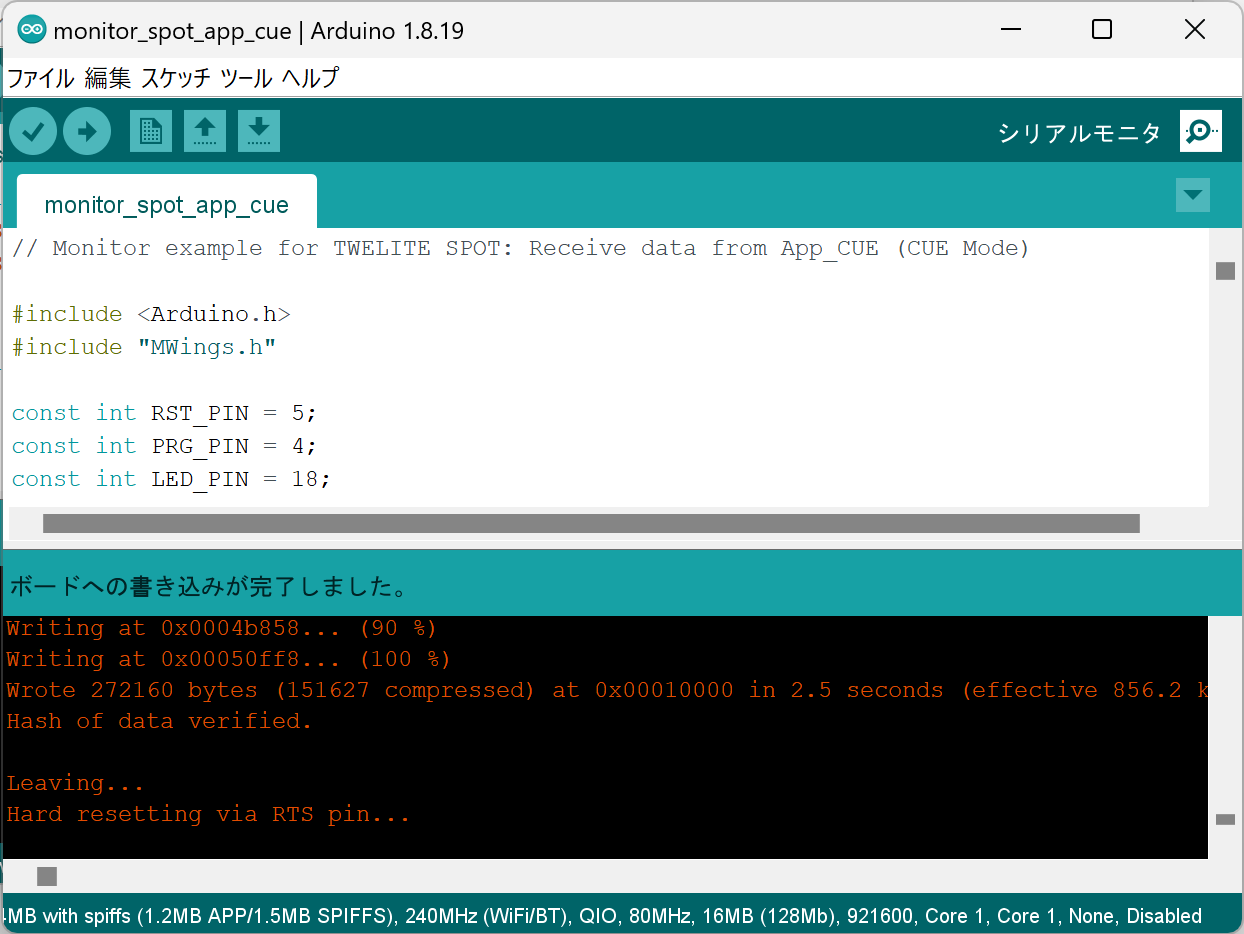
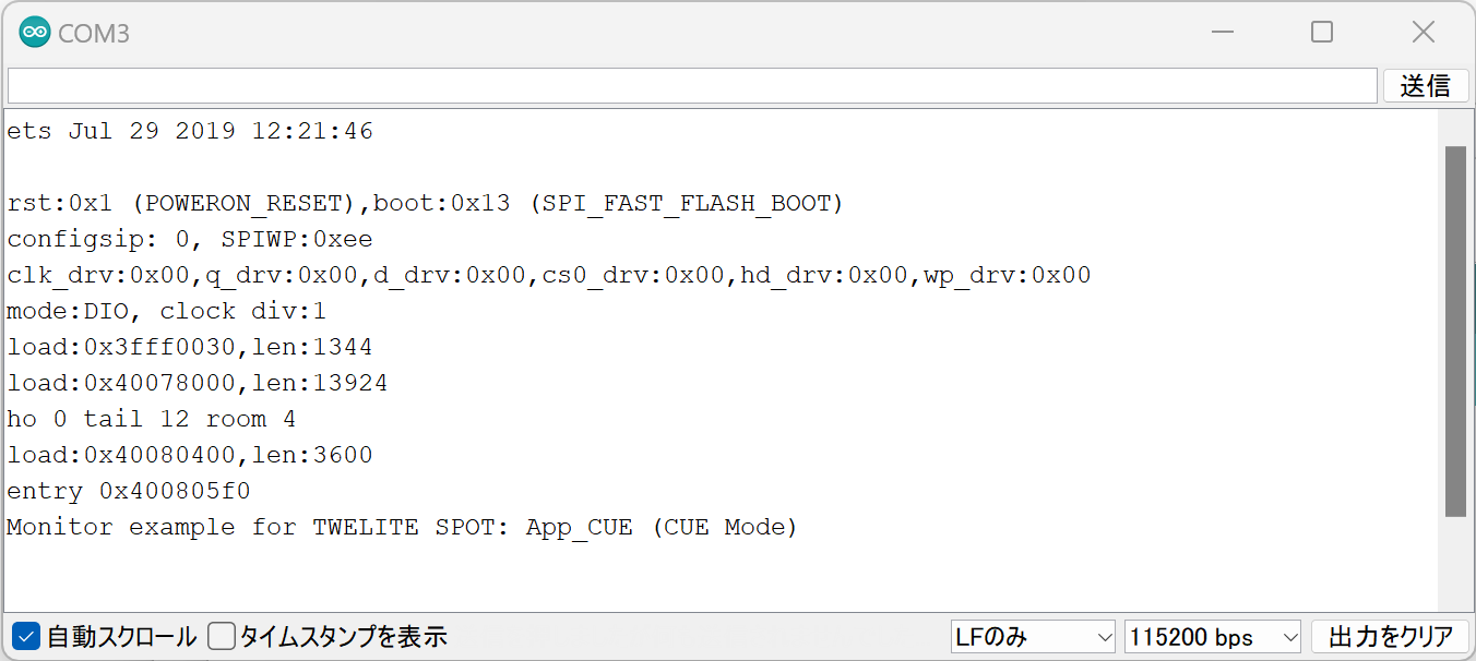
7. Confirm Startup 💬
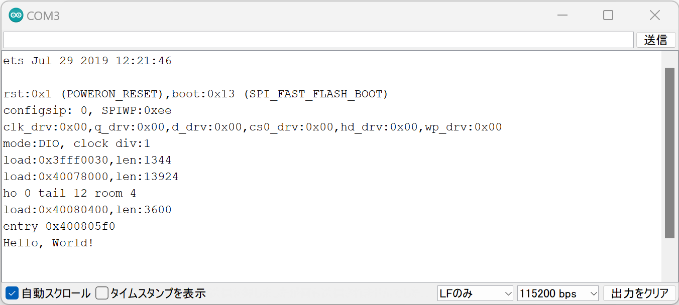
If the following string appears on the serial monitor, startup was successful.
Monitor example for TWELITE SPOT: App_CUE (CUE Mode)
Successful Startup Display
For TWELITE ARIA, the display will look like this:
Monitor example for TWELITE SPOT: App_ARIA (ARIA Mode)
8. Start TWELITE CUE ⚡
Insert a CR2032 coin battery into the TWELITE CUE. It will start operating immediately.
Inserting the Coin Battery
When TWELITE CUE starts normally, the LED on the logo side will blink.
If you have changed TWELITE CUE settings, please change the settings again and restore factory defaults (TWELITE CUE mode, Application ID 0x67720102, Frequency Channel 18).
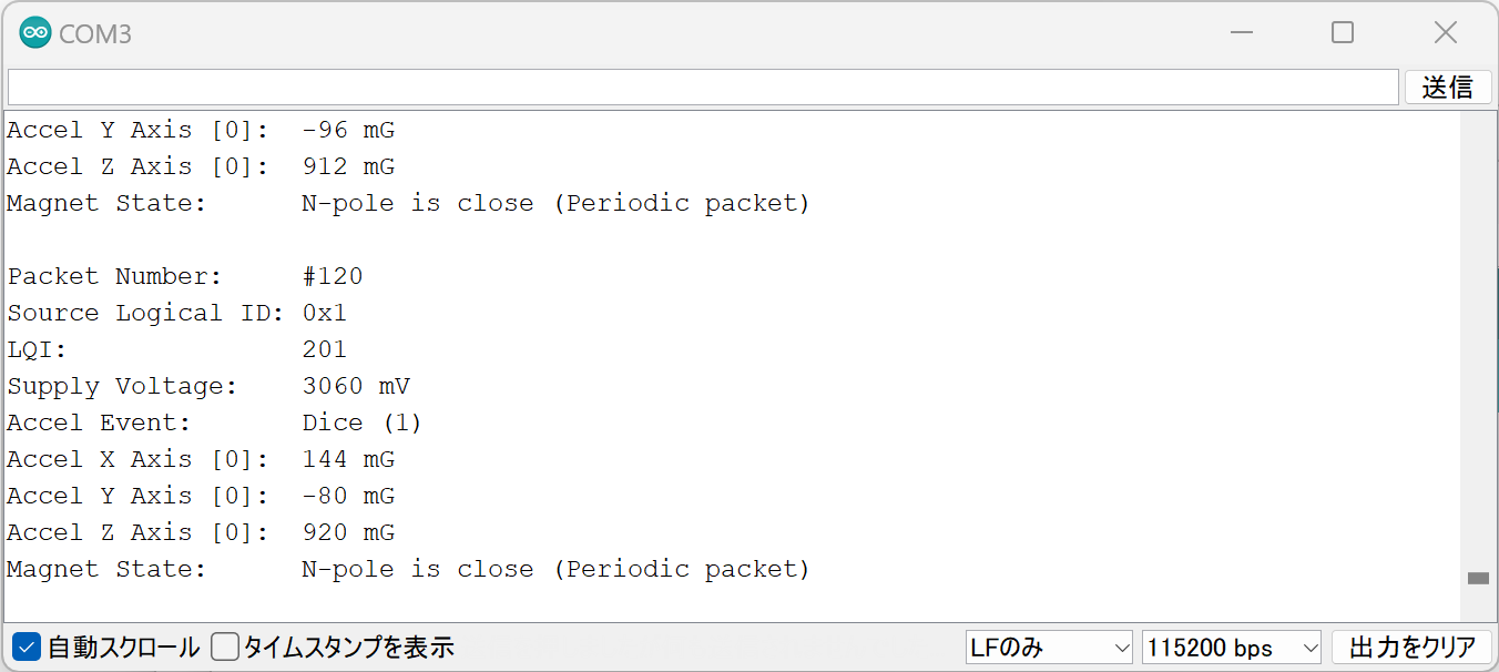
9. Confirm Reception 💬
If the following string appears on the serial monitor, data reception from TWELITE CUE was successful.
Packet Number:     #3
Source Logical ID: 0x1
LQI:               147
Supply Voltage:    3310 mV
Accel Event:       Dice (1)
Accel X Axis [0]:  72 mG
Accel Y Axis [0]:  -64 mG
Accel Z Axis [0]:  1000 mG
Magnet State:      Leaving or Not found
Successful Reception Display
For TWELITE ARIA, temperature and humidity data is output instead of acceleration data, so some parts of the display differ.
You have successfully read acceleration data from TWELITE CUE via the TWELITE installed on TWELITE SPOT!
Lines 19-21 initialize the serial ports and output the startup message to the serial monitor.
  Serial.begin(115200);
  Serial.println("Monitor example for TWELITE SPOT: App_CUE (CUE Mode)");
  Serial2.begin(115200);
Serial is used for communication with the Arduino IDE serial monitor. The baud rate is set to 115200 bps to match the serial monitor settings.
Serial2 is used for communication with the TWELITE Parent installed on TWELITE SPOT. This is also set to 115200 bps to match the Parent’s initial settings.
The TWELITE Parent’s serial communication initial settings are 115200 bps / 8N1.
TWELITE Initialization
Lines 24-26 call Twelite.begin() to configure and start the TWELITE Parent on TWELITE SPOT.
Twelite.update() reads packet data (ModBus ASCII format) from the TWELITE Parent one byte at a time.
By repeatedly calling Twelite.update() inside loop(), the parsing of packet data from the TWELITE Parent progresses. When packet parsing is complete, events like those described above are called.
Blocking calls such as delay() may cause packet data reading to fall behind. Always implement time-consuming processes asynchronously and keep the loop() function running as fast as possible.
You have learned how to read acceleration data from TWELITE CUE via TWELITE installed on TWELITE SPOT!
For further steps, see the sketch explanation below and Related Information.