What You Need
-
Wireless LAN Gateway TWELITE SPOT
- USB-C cable for power
- USB AC adapter (capable of supplying 1A or more)
-
Acceleration Sensor Wireless Tag TWELITE CUE (If you do not have one, please purchase 👉 List of Retailers)
- CR2032 coin battery
-
USB Adapter TWELITE R3 (If you do not have one, please purchase 👉 List of Retailers)
- USB-C cable for communication
- 💻 Computer
Setting Up the Environment
1. Install the Development Environment 🚛
If you have not set up the environment described in Basic Firmware Development Using ESP32, please do so first.
2. Configure the Board Settings ⚙️
Set the board type to ESP32 Dev Module and configure as shown below.
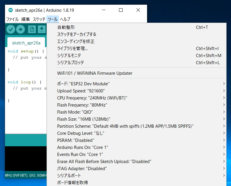
Settings After Configuration
3. Install the Library 🚚
Install the MWings Library required to use TWELITE from ESP32.
Open Sketch -> Include Library -> Manage Libraries…
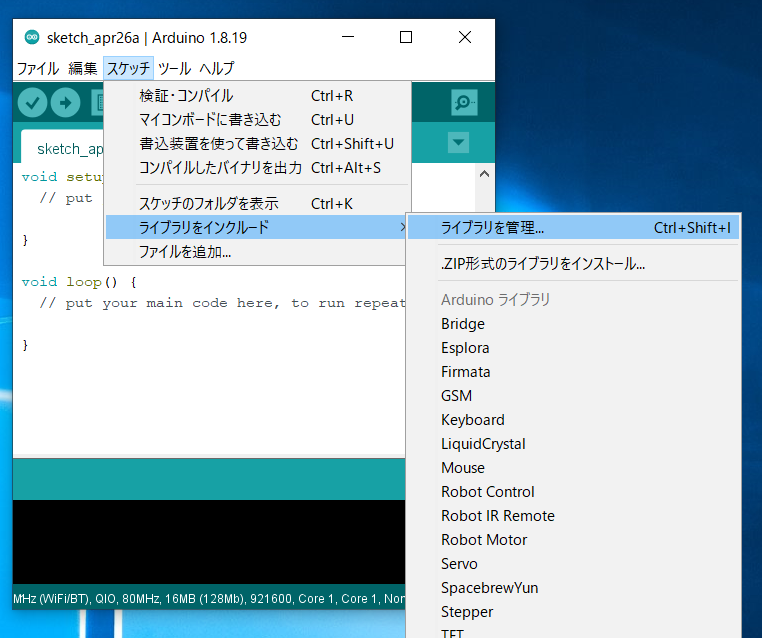
Location of Library Manager
Type MWings in the search box and install MWings.
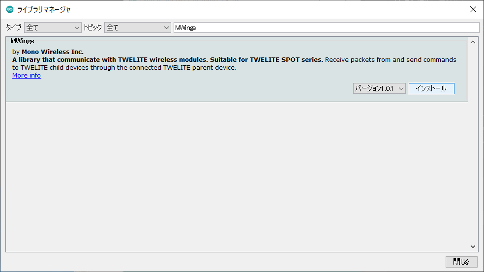
Library Manager
Prepare the TWELITE SPOT
1. Remove the Cover ⛏️
Remove the top cover of the TWELITE SPOT case.
2. Connect the Cables 🔌
Connect TWELITE R3 / R2 to the ESP32 7P interface labeled ESP32, then supply 5V power to the USB-C connector on the side.
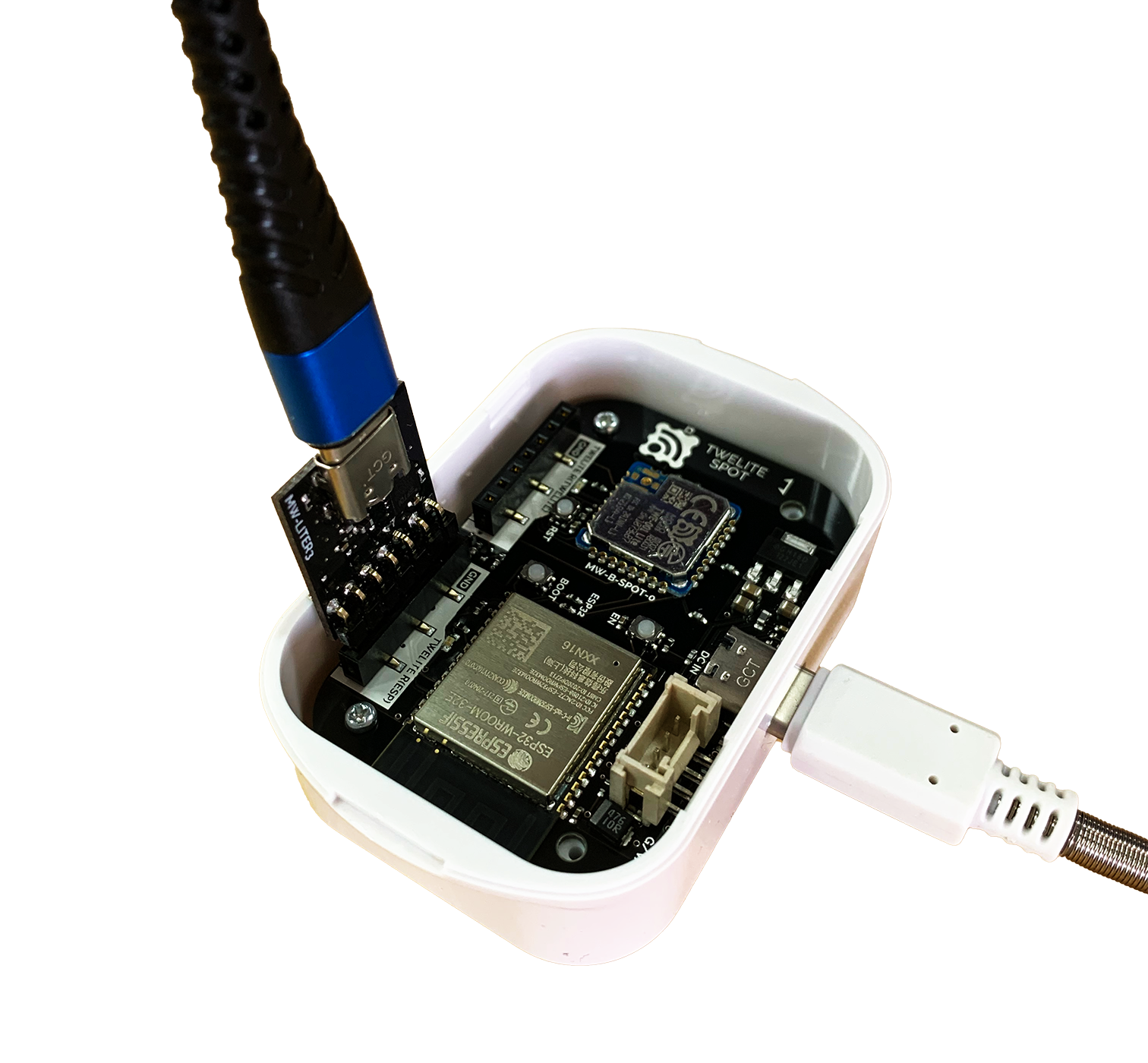
Connection Example (ESP32)
Run the Sketch First
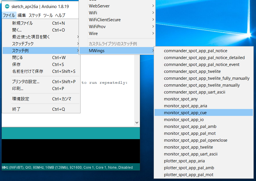
1. Open the Sample 📂
Launch Arduino IDE, then select File -> Examples -> MWings -> monitor_spot_app_cue.
2. Select the Serial Port ⚙️
From the Tools -> Port menu, select the port of the connected device (TWELITE R series).
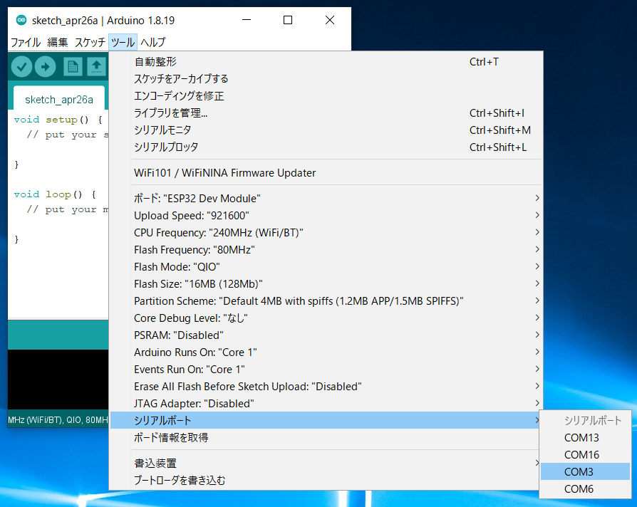
Serial Port Selection
3. Start the ESP32 👇
Start ESP32 in programming mode.
Press the reset switch EN(RST) and the ESP32 boot switch BOOT, then release in the order EN(RST) -> BOOT.
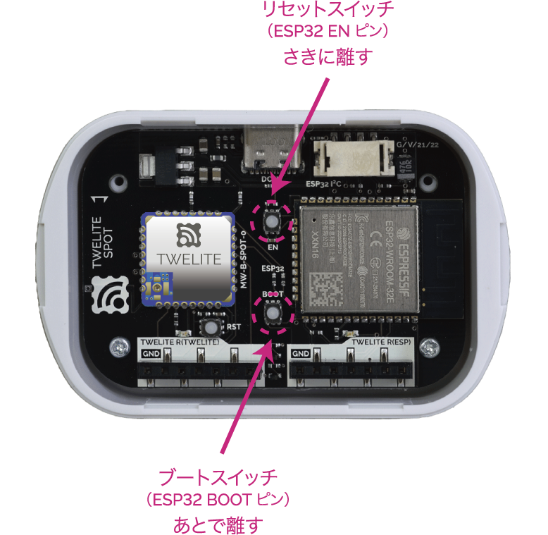
Button Locations
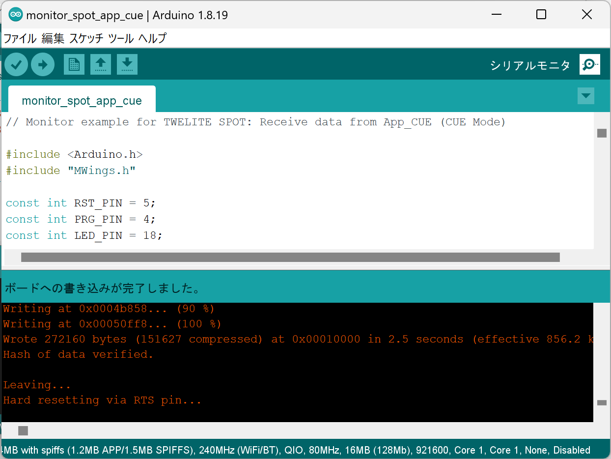
4. Write the Sketch ⚒️
Click the Upload button at the top of the Arduino IDE.
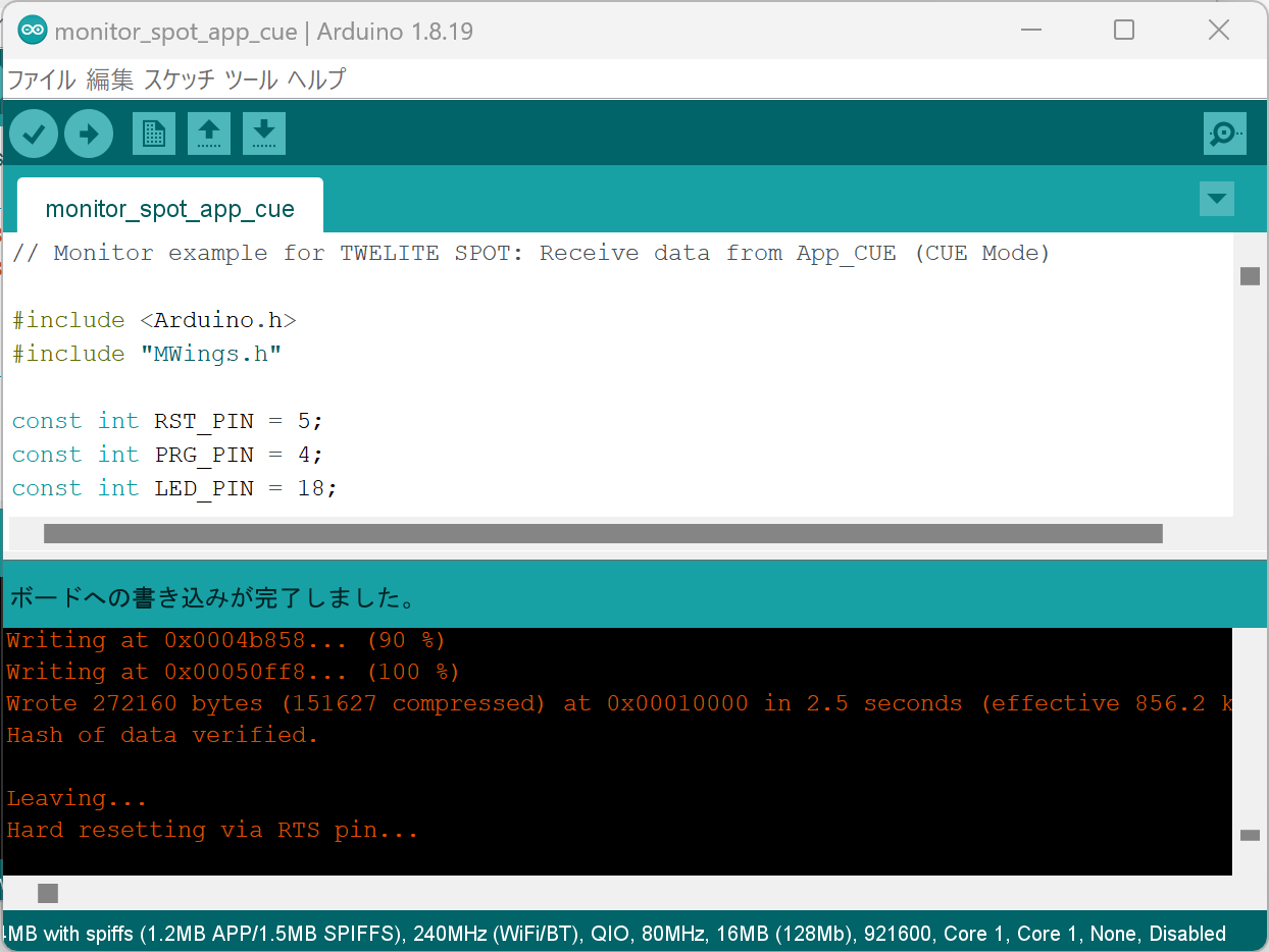
Upload Completion Screen
5. Open the Serial Monitor 🖥️
Open the Window
Click the Serial Monitor button at the top right of the Arduino IDE.
Serial Monitor Button at Top Right
Configure
Set the serial monitor baud rate to 115200.
6. Restart ESP32 🚀
After writing is complete, press and release the ESP32 reset switch EN(RST) on the TWELITE SPOT to reset the ESP32.
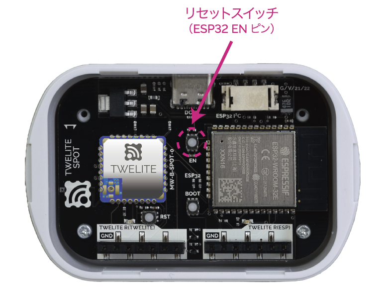
Reset Switch Location
Restarting ESP32 also restarts TWELITE.
- When ESP32 starts, the LED on the ESP32 side of the board blinks.
- When TWELITE starts, the LED on the TWELITE side of the board lights for 1 second.
7. Confirm Startup 💬
If the following string appears on the serial monitor, startup was successful.
Monitor example for TWELITE SPOT: App_CUE (CUE Mode)
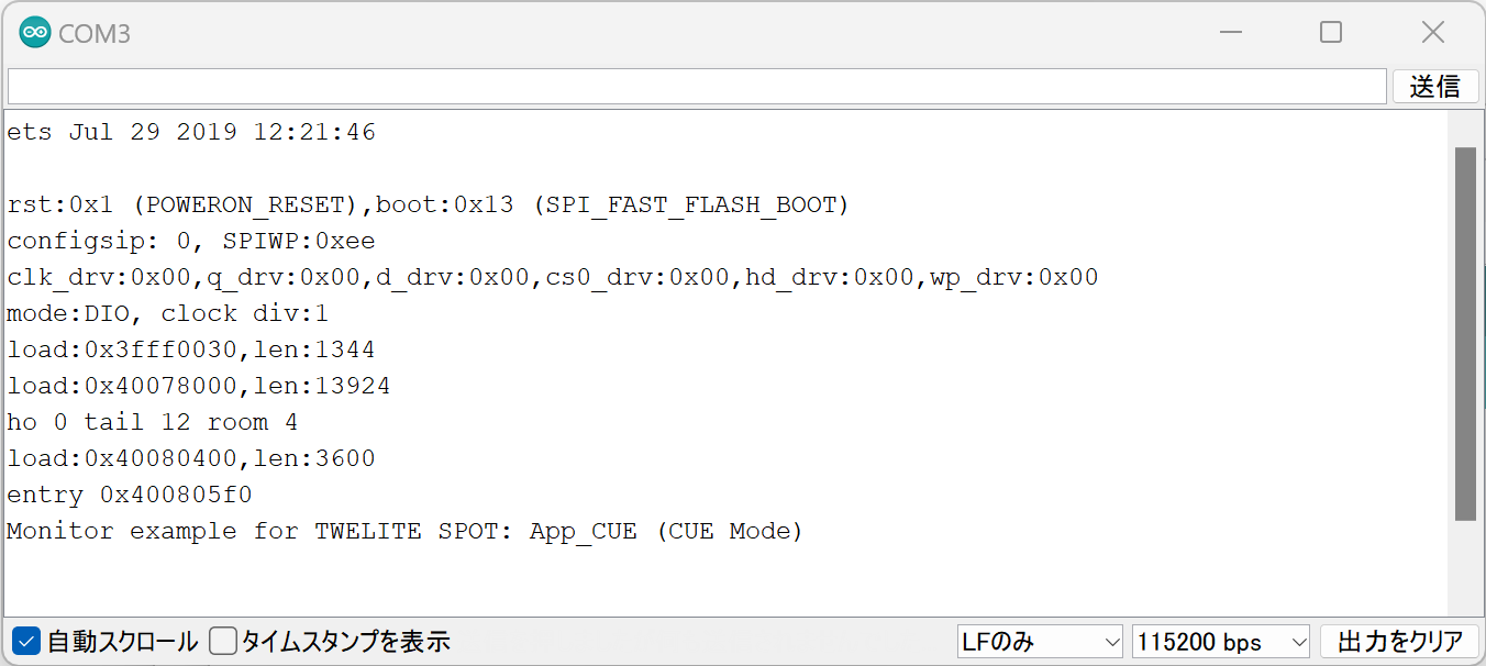
Successful Startup Display
For TWELITE ARIA, the display will look like this:
Monitor example for TWELITE SPOT: App_ARIA (ARIA Mode)
8. Start TWELITE CUE ⚡
Insert a CR2032 coin battery into the TWELITE CUE. It will start operating immediately.
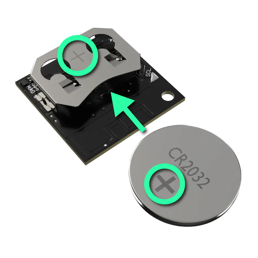
Inserting the Coin Battery
0x67720102, Frequency Channel 18).9. Confirm Reception 💬
If the following string appears on the serial monitor, data reception from TWELITE CUE was successful.
Packet Number:     #3
Source Logical ID: 0x1
LQI:               147
Supply Voltage:    3310 mV
Accel Event:       Dice (1)
Accel X Axis [0]:  72 mG
Accel Y Axis [0]:  -64 mG
Accel Z Axis [0]:  1000 mG
Magnet State:      Leaving or Not found
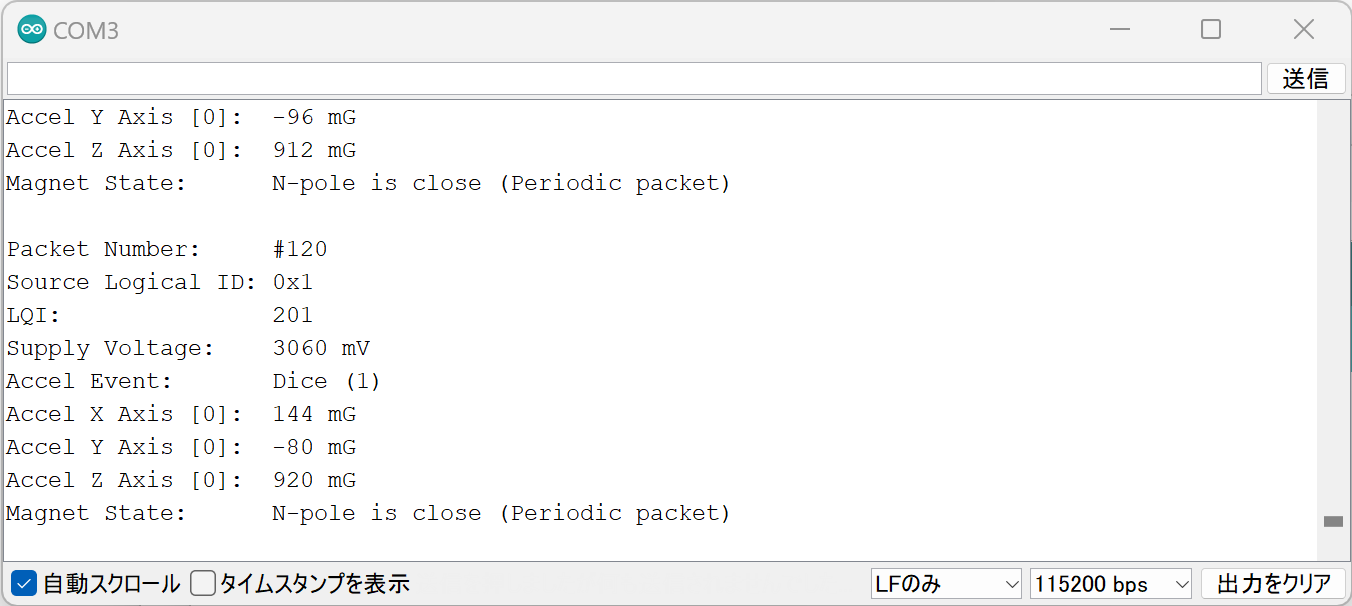
Successful Reception Display
Sketch Explanation
Here is a brief explanation of the sample sketch (monitor_spot_app_cue.ino).
Including the Library
Line 4 includes the MWings library you installed earlier.
#include "MWings.h"
Defining Pin Numbers
Lines 6-8 define the pin numbers.
const int RST_PIN = 5;
const int PRG_PIN = 4;
const int LED_PIN = 18;
| Name | Description |
|---|---|
RST_PIN | Pin number connected to the TWELITE RST pin |
PRG_PIN | Pin number connected to the TWELITE PRG pin |
LED_PIN | Pin number connected to the ESP32 LED on the board |
Do not change the RST_PIN and PRG_PIN numbers.
Changing these will prevent proper TWELITE startup.
Defining TWELITE Settings
Lines 10-11 define the settings applied to the TWELITE Parent installed in TWELITE SPOT.
const uint8_t TWE_CHANNEL = 18;
const uint32_t TWE_APP_ID = 0x67720102;
| Name | Description |
|---|---|
TWE_CHANNEL | TWELITE frequency channel |
TWE_APP_ID | TWELITE application ID |
Serial Port Setup
Lines 19-21 initialize the serial ports and output the startup message to the serial monitor.
  Serial.begin(115200);
  Serial.println("Monitor example for TWELITE SPOT: App_CUE (CUE Mode)");
  Serial2.begin(115200);
Serial is used for communication with the Arduino IDE serial monitor. The baud rate is set to 115200 bps to match the serial monitor settings.
Serial2 is used for communication with the TWELITE Parent installed on TWELITE SPOT. This is also set to 115200 bps to match the Parent’s initial settings.
TWELITE Initialization
Lines 24-26 call Twelite.begin() to configure and start the TWELITE Parent on TWELITE SPOT.
    Twelite.begin(Serial2,
                      LED_PIN, RST_PIN, PRG_PIN,
                      TWE_CHANNEL, TWE_APP_ID);
| Parameter | Type | Description |
|---|---|---|
Serial2 | HardwareSerial& | Serial port used for communication with TWELITE |
LED_PIN | int | Pin number connected to the status LED |
RST_PIN | int | Pin number connected to the TWELITE RST pin |
PRG_PIN | int | Pin number connected to the TWELITE PRG pin |
TWE_CHANNEL | uint8_t | TWELITE frequency channel |
TWE_APP_ID | uint32_t | TWELITE application ID |
Registering Packet Reception Event
Lines 29-49 call Twelite.on() to register the processing to be done when data is received from the TWELITE CUE.
Here, the received packet content is output to the serial monitor.
    Twelite.on([](const ParsedAppCuePacket& packet) {
        Serial.println("");
        Serial.print("Packet Number:     #");
        Serial.println(packet.u16SequenceNumber, DEC);
        Serial.print("Source Logical ID: 0x");
        Serial.println(packet.u8SourceLogicalId, HEX);
        Serial.print("LQI:               ");
        Serial.println(packet.u8Lqi, DEC);
        Serial.print("Supply Voltage:    ");
        Serial.print(packet.u16SupplyVoltage, DEC); Serial.println(" mV");
        Serial.print("Accel Event:       ");
        printAccelEvent(packet.u8AccelEvent);
        Serial.print("Accel X Axis [0]:  ");
        Serial.print(packet.i16SamplesX[0], DEC); Serial.println(" mG");
        Serial.print("Accel Y Axis [0]:  ");
        Serial.print(packet.i16SamplesY[0], DEC); Serial.println(" mG");
        Serial.print("Accel Z Axis [0]:  ");
        Serial.print(packet.i16SamplesZ[0], DEC); Serial.println(" mG");
        Serial.print("Magnet State:      ");
        printMagnetState(packet.u8MagnetState, packet.bMagnetStateChanged);
    });
This event is called only when a packet is received from the TWELITE CUE.
The received packet content is stored in the argument packet of type ParsedAppCuePacket.
packet contains the following data (the bold data are used in the code above).
| Data | Type | Description |
|---|---|---|
packet.u32SourceSerialId | uint32_t | Source Serial ID |
packet.u8SourceLogicalId | uint8_t | Source Logical Device ID |
packet.u16SequenceNumber | uint16_t | Sequence Number |
packet.u8Lqi | uint8_t | LQI (Radio Signal Quality Indicator) |
packet.u16SupplyVoltage | uint16_t | Supply Voltage (mV) |
packet.i16SamplesX | int16_t[10] | X-axis acceleration samples (mG) |
packet.i16SamplesY | int16_t[10] | Y-axis acceleration samples (mG) |
packet.i16SamplesZ | int16_t[10] | Z-axis acceleration samples (mG) |
packet.u8SampleCount | uint8_t | Number of samples |
packet.bHasAccelEvent | bool | true if acceleration event is present |
packet.u8AccelEvent | uint8_t | Acceleration Event ID |
packet.u8MagnetState | uint8_t | Magnetic Event ID |
packet.bMagnetStateChanged | bool | true if magnetic sensor state changed |
For TWELITE ARIA, use the ParsedAppAriaPacket type.
Twelite.on() can be written for each data type, for example, you can add the following to handle data received from TWELITE ARIA.
Twelite.on([](const ParsedAppAriaPacket& packet) {
    // Handle packet...
});
For details, see the API Reference.
Updating TWELITE Data
Line 55 calls Twelite.update().
Twelite.update();
Twelite.update() reads packet data (ModBus ASCII format) from the TWELITE Parent one byte at a time.
Twelite.update() inside loop(), the parsing of packet data from the TWELITE Parent progresses. When packet parsing is complete, events like those described above are called.delay() may cause packet data reading to fall behind. Always implement time-consuming processes asynchronously and keep the loop() function running as fast as possible.For further steps, see the sketch explanation below and Related Information.