Basic Operation Check
Connect the TWELITE STICK
Connect the TWELITE STICK to the USB port of your PC.
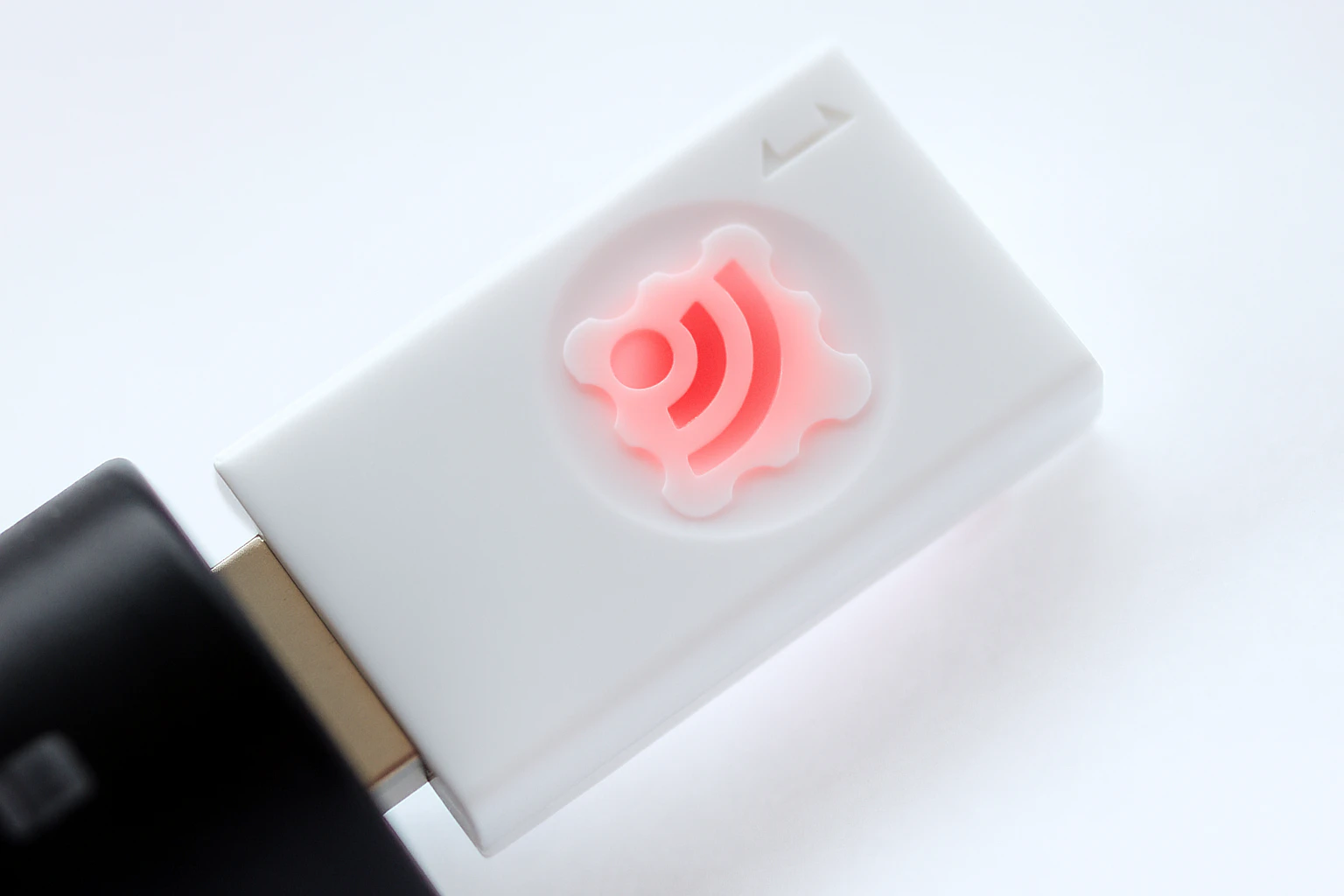
The factory-shipped TWELITE is set to Parent mode of the Parent and Repeater App. It can send and receive data with child devices of the TWELITE series, and the logo mark should light up magenta.
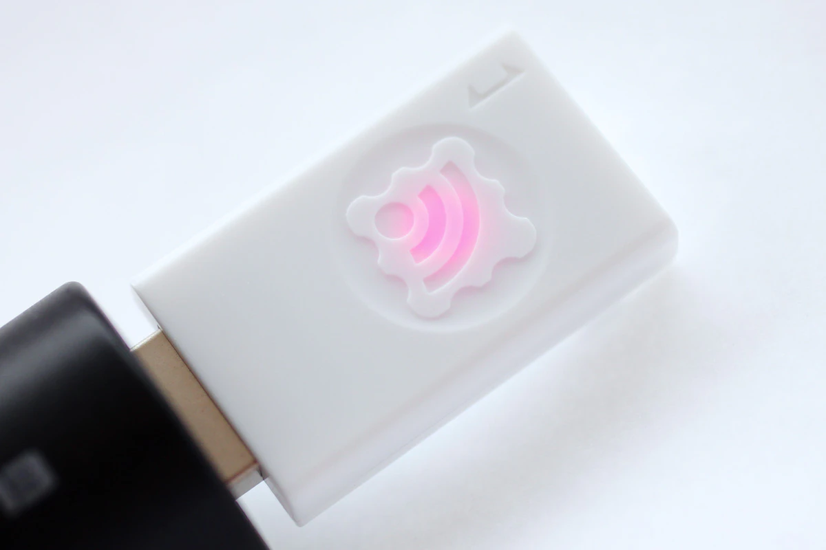
Factory default state
Check the Startup Message
To verify the operation of the TWELITE STICK, first check the startup message output during boot.
With TWELITE STICK connected, launch TWELITE_Stage from the MWSTAGE folder. On the “Serial Port Selection” screen, TWELITE STICK will be listed.
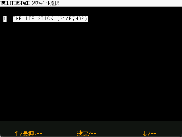
Serial Port Selection
If TWELITE STICK does not appear, try installing the FTDI D2XX driver.
On Windows, it appears as a COM port in Device Manager. On other systems, it appears as /dev/tty*.
When you select TWELITE STICK, the application proceeds to the main menu.
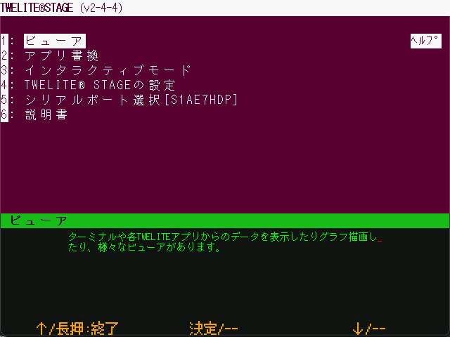
Main Menu
Selecting Viewer will take you to the viewer selection menu.
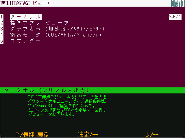
Viewer
ESC key.Selecting Terminal will open a VT-100 compatible terminal screen, just like a typical terminal application.
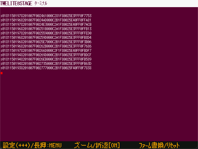
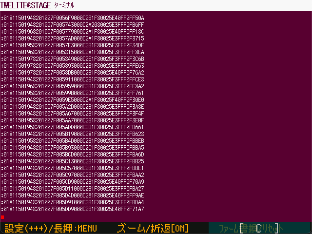
Terminal Screen
By default, TWELITE STICK may already be outputting received packet data, as shown above.
Long-press the Firmware Write/Reset button in the lower-right corner to reset the TWELITE.
Long-press the lower-right corner to reset
A startup message will appear.
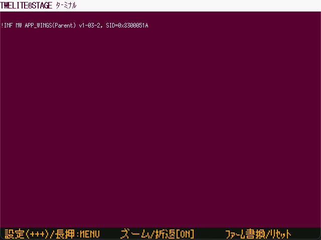
Example of Startup Message Output
In the example above, the following message is shown:
!INF MW APP_WINGS(Parent) v1-03-2, SID=0x8300051A
If you see !INF MW APP_WINGS(Parent) in the output, it indicates that the Parent mode of the Parent and Repeater App (App_Wings) is running.
Communicating with a TWELITE DIP Child Device
This section describes how to verify communication with a child device using the TWELITE DIP.
The TWELITE DIP runs the Extremely Simple! Standard App (App_Twelite) that is written at the factory.
Preparing the TWELITE DIP
Connect a switch between DI1 and GND, and connect an LED between DO1 and VCC. This setup is the same as used in Basic Communication Between Terminals Using the Extremely Simple! Standard App.
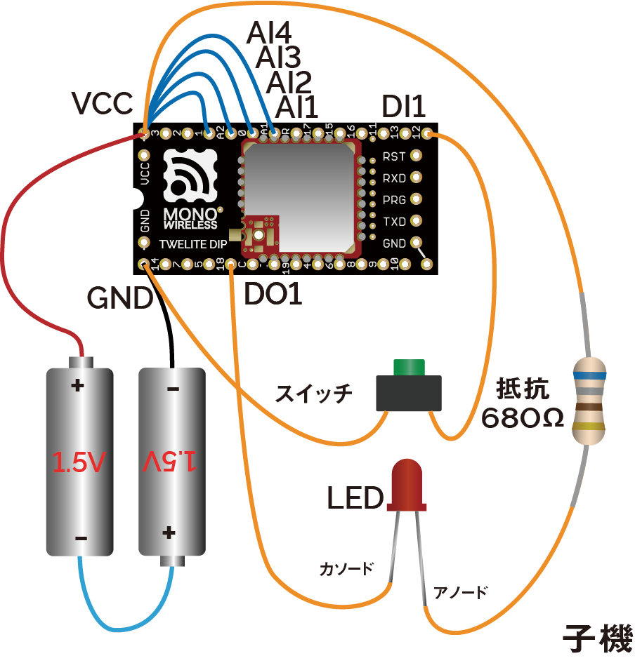
Example wiring for child device
By using a TWELITE STICK in place of a TWELITE DIP parent, you can detect the button state on the PC side or control the LED from the PC.
Connecting the TWELITE STICK
Connect the TWELITE STICK to the USB port of your PC.
If it is set to Parent mode of the Parent and Repeater App, it will light up magenta.

Waiting in Parent Mode
Device Settings
No configuration changes are required. Communication will begin immediately using the factory default settings.
However, for confirmation, let’s check the current configuration.
To change TWELITE settings via UART, start the device in Interactive Mode. TWELITE STAGE APP provides functionality for working with Interactive Mode.
From the main menu, select Interactive Mode.
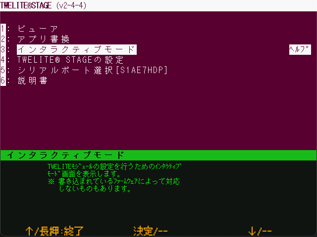
Main Menu
On the next screen, click anywhere or press the Enter key to continue.
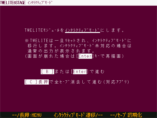
Confirmation Screen
If the following screen appears, the mode has started successfully.
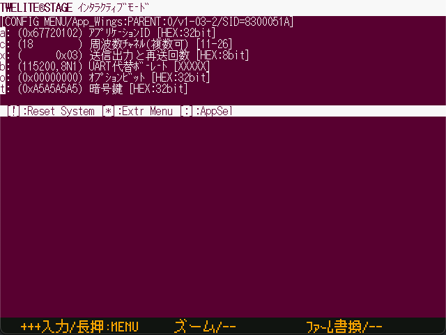
Interactive Mode
If the Channel value, which physically separates networks, is 18, and the Application ID value, which logically separates networks, is 67720102, communication with the factory-shipped TWELITE DIP will be possible.
How to Operate Interactive Mode
- Enter the ID shown on the left to edit each item (e.g., enter
ato edit the Application ID) - After selecting an item, type the value and press the
Enterkey to confirm, or press theESCkey to cancel - Press the
Skey to apply the settings you’ve entered - To reset all settings to default, press the
Rkey to reset, then press theSkey to apply
For details about each setting item, see the documentation for the Parent and Repeater App (App_Wings).
Logo Lighting
With the TWELITE STICK connected to your PC, press the switch connected to DI1 on the TWELITE DIP.
If operating correctly, the logo will glow red and brighter while the button is pressed.
Logo lights up red when DI1 is pressed
DI2, the TWELITE STICK will glow green. If AI1 is disconnected from VCC and a voltage between 0–2V is applied, the brightness will vary depending on the button press on DI1 or DI2.Standard App Viewer
TWELITE STAGE APP includes a feature to display data received from child devices running the Extremely Simple! Standard App.
Let’s read the status of the switch connected to DI1.
From the main menu, select Viewer.
Main Menu
On the viewer selection screen, select Standard App Viewer.
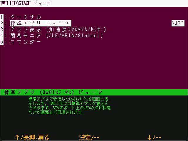
Viewer Selection
The Standard App Viewer displays the latest data received by the TWELITE STICK from the Extremely Simple! Standard App.
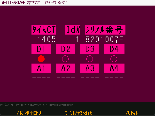
Standard App Viewer
When you press the switch connected to DI1 on the TWELITE DIP, the D1 indicator will light up in red.
Standard App Viewer Items
Time CT: Timestamp of the packetId#: Logical Device ID of the child deviceSerial Number: Serial ID of the child device (engraved on the can)Dx: State of theDIxpinsAx: Voltage input to theAIxpins (inmV, ranging from0mVto2000mV)
Standard App Commander
TWELITE STAGE APP also includes a function to send data to child devices running the Extremely Simple! Standard App. Let’s try controlling the LED connected to DO1.
From the main menu, open Viewer.
Main Menu
On the viewer selection screen, choose Commander.
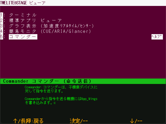
Viewer Selection
Select App_Twelite 0x80 Command.
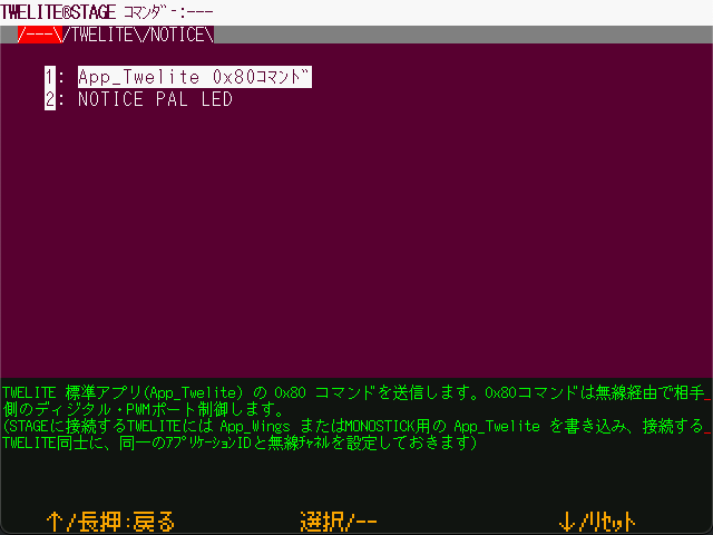
Standard App Commander
Click on DI1(1) or press the 1 key to control the lighting state of DI1.
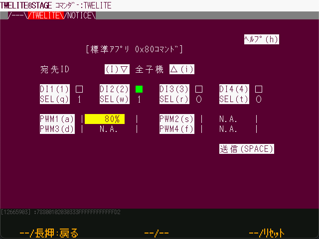
Commander Screen
Standard App Commander Items
Destination ID: Logical Device ID of the target device to which you want to send a state changeDIx(x): State change of the target device’sDOxpinSEL(x): Enable flag forDIx(x)PWMx(x): Change the duty cycle of the target device’sPWMxpinSend (SPACE): Re-send with the current state
Communicating with TWELITE ARIA
This section describes how to verify communication with the temperature and humidity sensor tag TWELITE ARIA.
TWELITE ARIA runs the ARIA App (App_ARIA) that is written at the factory.
Preparing TWELITE ARIA
Insert a CR2032 battery into the TWELITE ARIA.
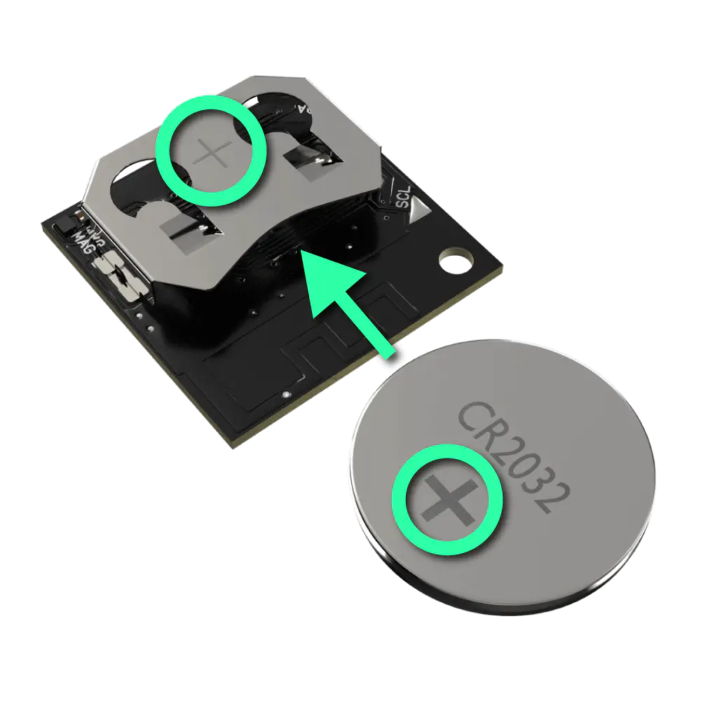
Insert CR2032 battery
By using a TWELITE STICK as the parent device for TWELITE ARIA, you can obtain temperature, humidity, and magnetic proximity data on your PC.
Connecting the TWELITE STICK
Connect the TWELITE STICK to the USB port of your PC.
If it is set to Parent mode of the Parent and Repeater App, it will light up magenta.
Waiting in Parent Mode
Device Settings
No configuration changes are needed. Communication will start immediately with the factory default settings.
If the Channel, which physically separates networks, is set to 18, and the Application ID, which logically separates networks, is set to 67720102, then communication with the factory-configured TWELITE ARIA is possible.
Logo Lighting
With TWELITE STICK connected to the PC, bring a magnet close to the Hall sensor on TWELITE ARIA.
If working properly, TWELITE ARIA will send a packet each time a magnet is brought near, and TWELITE STICK’s logo will flash in response.
Simple Monitor
TWELITE STAGE APP includes a simple monitor feature to display data received from TWELITE ARIA.
From the main menu, select Viewer.
Main Menu
On the viewer selection screen, choose Simple Monitor (CUE/ARIA/Glancer).
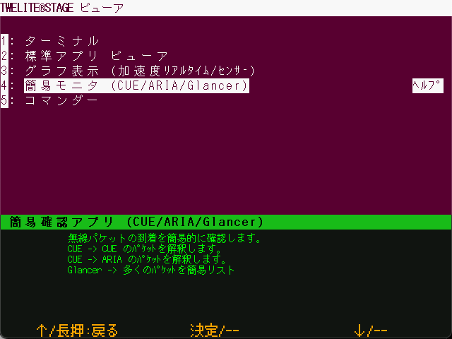
Viewer Selection
Next, select Simple Monitor for TWELITE ARIA.
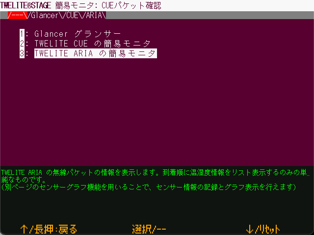
Simple Monitor Selection Screen
The Simple Monitor screen displays the latest data received by the TWELITE STICK from TWELITE ARIA.
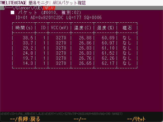
Simple Monitor
When a magnet is brought close to TWELITE ARIA, a new packet is received.
Simple Monitor Items
Packet: Information of the latest packet#: Packet sequence number (includes all types)Type: Packet type ID (fixed as02)ID: Logical Device IDAD: Serial ID (engraved on the can of the device)LQ: Link Quality Indicator (LQI, higher is better, range: 0–255)SQ: Packet sequence number based on TWELITE ARIA data
- History
Time: Timestamp when received (not included in packet)ID: Logical Device IDVCC(mV): Supply voltage of TWELITE ARIATemp(C): TemperatureHumidity(%): Relative humidityMagnet: Hall sensor result (None,[N],[S])
Sensor Graph
TWELITE STAGE APP includes a feature to graphically display temperature and humidity data received from child devices.
From the main menu, open Viewer.
Main Menu
On the viewer selection screen, select Graph View (Accelerometer Real-Time / Sensor).
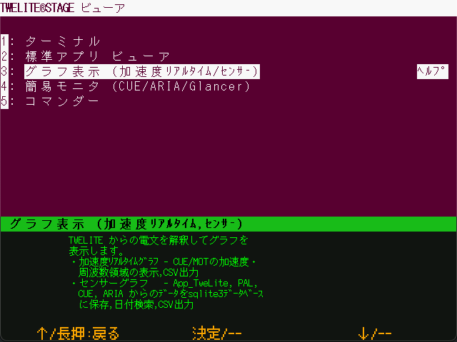
Viewer Selection
Next, select Sensor Graph.
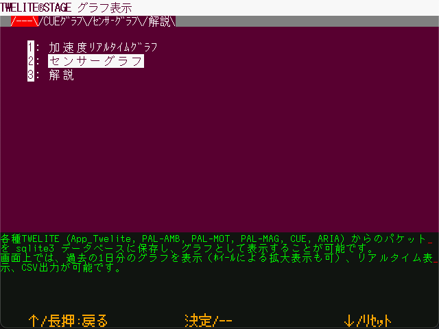
Graph Selection Screen
From the list of nodes on the right, select one that begins with ARA.
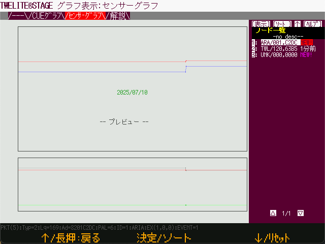
Node Selection
By default, data for the past 24 hours is displayed. To view the most recent data, click [Live >>].
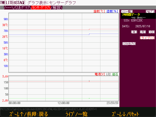
24-Hour Data
The latest data will be displayed. Bring a magnet close to the sensor or warm the sensor near the 7P interface to observe the changes in values.
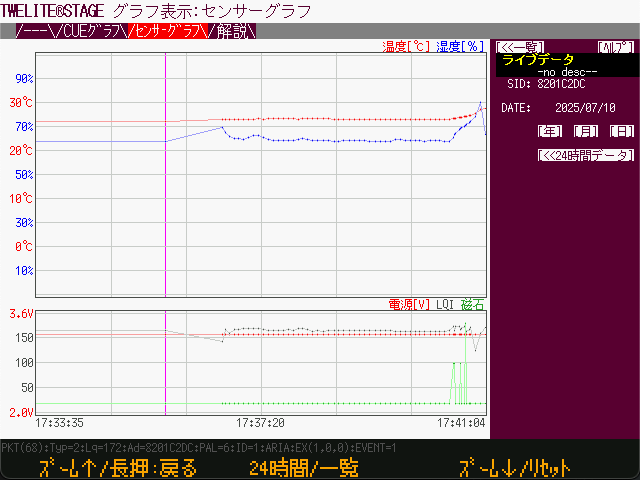
Live Data