Other technical information related to TWELITE is provided here.
This is the multi-page printable view of this section. Click here to print...
For suitable output, we recommend to use Google Chrome (15+) or Microsoft Edge (79+).
Tips
- 1: Glossary
- 2: Software Development
- 3: Hardware Development
1 - Glossary
Explanation of terms related to TWELITE.
1.1 - What is IEEE802.15.4?
Meaning of IEEE802.15.4
IEEE802.15.4 is a wireless standard suitable for building wireless sensor networks. It supports two-way communication and is used for collecting information from sensors or remotely controlling terminal devices.
TWELITE is a wireless microcontroller module compliant with IEEE802.15.4.
It features low power consumption and stable communication performance.
Features
The features of IEEE802.15.4 are as follows.
International Standard
IEEE802.15.4 is a standard established by IEEE (Institute of Electrical and Electronics Engineers), headquartered in the United States. Being a standard means that products based on the specification are supplied by multiple vendors rather than relying on a single proprietary standard, ensuring stability. When using the 2.4 GHz ISM band, it can be sold not only in Japan but worldwide.
Two-Way Digital Communication
IEEE802.15.4 adopts Offset Quadrature Phase Shift Keying (O-QPSK) as the modulation method in the 2.4 GHz band and Direct Sequence Spread Spectrum (DSSS) as the spreading method, making it resistant to interference noise and enabling stable two-way digital communication.
Encrypted Communication
IEEE802.15.4 ensures data communication security using strong encryption technology, 128-bit AES encryption, which is also used in internet banking and online shopping.
Low Power Consumption
The design philosophy of IEEE802.15.4 emphasizes low power consumption. It enables operation for years without battery replacement, operation with coin batteries, or even operation powered by energy harvesting devices that extract power from light, heat, vibration, etc. This makes wireless use possible in locations that were previously difficult to install.
Low Speed
Compared to wireless LAN or Bluetooth, IEEE802.15.4 limits communication speed. This is to optimize the communication speed (250 kbps) for wireless sensor networks, achieving low power consumption and high communication sensitivity. Although described as low speed, it provides sufficient speed for building sensor networks.
Standard Protocol
IEEE802.15.4 is adopted as the physical layer for wireless communication by many standardization organizations such as the ZigBee Alliance, Thread Group, and IETF. Various standard communication protocols are implemented on top of IEEE802.15.4. This flexibility in protocol selection is also a characteristic of IEEE802.15.4, allowing it to flexibly support wireless sensor networks.
Specifications
| Operating Frequency | 2.4 GHz | Usable worldwide |
| Number of Channels | 16 | 16 channels can communicate simultaneously |
| Modulation Method | O-QPSK, DSSS | Resistant to noise |
| Data Rate | 250 kbps | Optimized for sensor networks |
| Current Consumption (During Communication) | <30 mA | Low power consumption |
| Encryption | AES-128 bit | Strong security available |
| Network Node Capacity | 65,535 | Supports large-scale networks |
IEEE802.15.4 Data Frame
Below is the packet structure defined in the IEEE 802.15.4 data frame.
| PHY Header (SHR, PHR) | PHY Payload (PSDU) Maximum 127 bytes | |||||||
| OCTET | 4 | 1 | 1 | 2 | 1 | 4~20 | n | 2 |
| Contents | Preamble Sequence | Frame Delimiter Start Position | Frame Length | Frame Control | Sequence Number | Address Information | MAC Payload | FCS |
OCTET is a unit representing data volume, defined as 1 OCTET = 8 bits.
While not common nowadays, some systems do not treat 1 byte as 8 bits, so the byte unit can be ambiguous. In communication definitions, OCTET, defined as 8 bits, is used.
- When programming using the IEEE802.15.4 MAC API, the areas to be aware of are frame control, address information, and data.
- The sequence number is automatically assigned by the MAC layer, so users cannot obtain or set this value.
- LQI (Link Quality Indicator) information is not included in the packet information. It is obtained from the receiver circuit at packet reception.
- The maximum packet length is 127 OCTETs (PHY payload: PSDU).
- In typical communication, when address information is 8 OCTETs (16-bit short addresses for both sender and receiver), the data area (MAC payload) can be up to 127 - 2 (frame control) - 1 (sequence number) - 8 (address) - 2 (FCS) = 114 OCTETs.
- In stacks like ZigBee PRO, headers used by the stack reduce the data area available to users.
- Communication time for maximum packet length is about 4.3 ms.
- The composition of address information consists of the following combinations:
- Source (Src) PAN ID (2 OCTET)
- Source (Src) address (0: no address, 2: short address, 8: extended address)
- Destination (Dst) PAN ID (2 OCTET)
- Destination (Dst) address (0: no address, 2: short address, 8: extended address)
- Typically, the structure is Src PAN ID, Src short address, Dst PAN ID, Dst short address, totaling 8 OCTETs.
- It is also possible to use the MAC address only for the Src address. In this case, the total is 14 OCTETs: Src PAN ID, Src MAC address, Dst PAN ID, Dst short address.
| Addressing Mode | Address Area Size |
| No source or destination address (PAN ID only) | 4 |
| 118 | |
| Source and destination use 16-bit short addresses | 8 |
| 114 | |
| Source and destination use 64-bit extended addresses | 20 |
| 102 |
Addressing modes other than the above combinations are also possible.
What is IEEE802.15.4g?
IEEE802.15.4g is a communication method intended for smart meter communication. The frequencies usable with IEEE802.15.4g vary by country; in Japan, the 920 MHz band physical layer (PHY) can be used. The MAC layer is also being standardized as IEEE802.15.4e. Neither is compatible with IEEE802.15.4. In Japan, IEEE802.15.4g is expected to be a standard mainly for enabling automatic gas meter reading.
What is IEEE802.15.4k?
IEEE802.15.4k is a communication method intended for smart grid communication. It is called Low Energy Critical Infrastructure Monitoring (LECIM) and aims to provide reliable communication over low speed and long distances.
Wireless Microcontroller Connecting Things: TWELITE
There are many everyday situations where you want to operate something remotely or monitor something. Wireless is suitable when you want to know the status of a distant object or control it remotely. However, when making things wireless, various constraints such as battery life, communication distance, simultaneous connections, and size make it difficult to realize with conventional wireless technologies. Thus, wireless technology to connect things was born.
Our company offers TWELITE, a wireless microcontroller compliant with IEEE802.15.4, optimal for building wireless sensor networks, supporting customers in simplifying communication function development for wireless sensor network-related devices and accelerating time to market.
It is aimed at those who want to easily use wireless functions to create devices for collecting various sensor information wirelessly or creating various remote controls but find it too challenging. Using TWELITE DIP, you can easily acquire wireless functionality.
It supports a wide range of users from hobbyists and learners to various prototyping and small-lot production.
Evaluation and Development of Wireless Sensor Networks (IEEE802.15.4 Compliant)
Our company also provides development tools for monitoring various sensor information wirelessly applicable to wireless sensor networks and for conducting communication quality measurements.
2 - Software Development
Various tips and notes related to TWELITE software development.
2.1 - UART Communication Without the STAGE App
Use CoolTerm for UART communication instead of the TWELITE STAGE App
The terminal function of the TWELITE STAGE app is not suitable for advanced UART operations. This article introduces how to use the general-purpose software CoolTerm to access interactive mode and send binary data over UART.
We assume no responsibility for the use of external tools.
Also, please refrain from asking questions regarding external tools.
When the TWELITE STAGE App is Not Suitable
The Terminal of the TWELITE STAGE app is intended only for simple evaluation purposes. Therefore, for advanced UART communication such as the serial communication app’s format modes (ASCII / Binary), there are the following issues:
- When inputting a sequence to TWELITE’s
RX, you must paste a pre-copied string usingAlt+V/⌘+V. - Binary data cannot be handled in HEX (hexadecimal) notation.
Overview of CoolTerm
CoolTerm is a general-purpose software specialized for serial communication. Unlike TeraTerm, it can handle binary data without using debug mode and supports multiple platforms.
Using ASCII and Binary format modes of the serial communication app simultaneously
Installation
Please download the files from the author’s homepage.
Configuration
In CoolTerm, you can name the serial port and its associated settings.
Here, we introduce the necessary settings to adapt to the default TWELITE series.
Settings can be changed from the Options menu.
Serial Port
Within Options, under Serial Port, check the following settings:
Port: The port used by the TWELITE R or MONOSTICKBaudrate: Set to115200bps
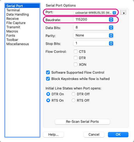
Example settings
Terminal
Within Options, under Terminal, mainly check the following settings:
Terminal Mode:Raw ModeEnter Key Emulation:CR+LF
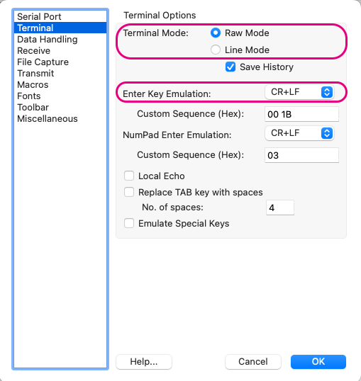
Example settings
When inputting ASCII data (excluding interactive mode), you may set Terminal Mode to Line Mode.
In Line Mode, pressing the Enter key sends the typed data at once.
Data Handling
Within Options, under Data Handling, mainly check the following settings:
Clear Display on: CheckESC[2J](enables screen clearing in interactive mode)- Check
Handle BS and DEL Characters(enables character deletion in interactive mode) Text Encoding:UTF8
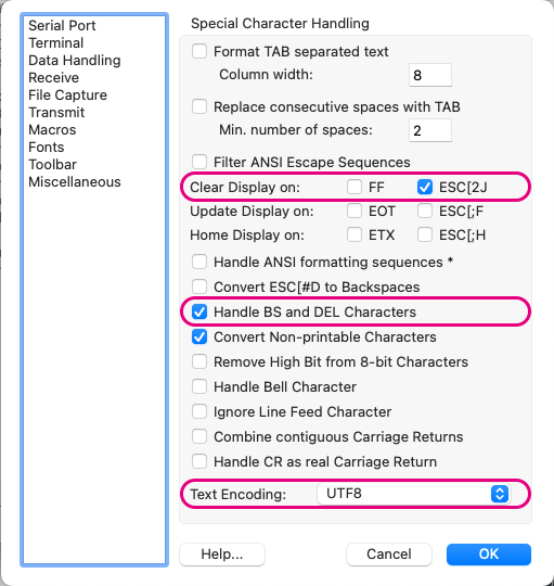
Example settings
Transmit
Within Options, under Transmit, mainly check the following settings:
Send String Options: CheckTerminate 'Send String' DataTermination String:0D 0A(appends CRLF at the end in the send screen)
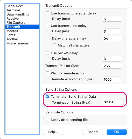
Example settings
In the serial communication app’s format mode (binary), do not check this box (CRLF is not used).
Usage Examples
Interactive Mode
For interactive mode, it is recommended to set Options > Terminal > Terminal Mode to Raw Mode.
After clicking Connect, select the main screen and input the + character three times.
You can use interactive mode by directly typing characters just like in the TWELITE STAGE app.
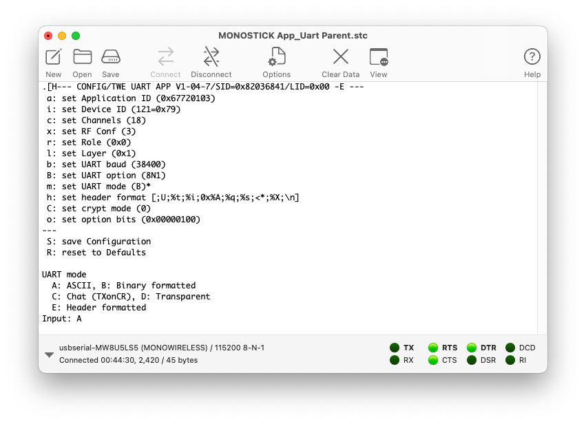
Example of using interactive mode
For operating interactive mode, please refer to the TWELITE APPS manual.
Serial Communication App Format Mode (ASCII)
When handling sequences composed of ASCII strings starting with : and ending with CRLF, as in the serial communication app’s ASCII format mode, setting Options > Terminal > Terminal Mode to Line Mode is convenient.
You can input line by line using the Enter key, and press the ↑ cursor key to refer to the history.
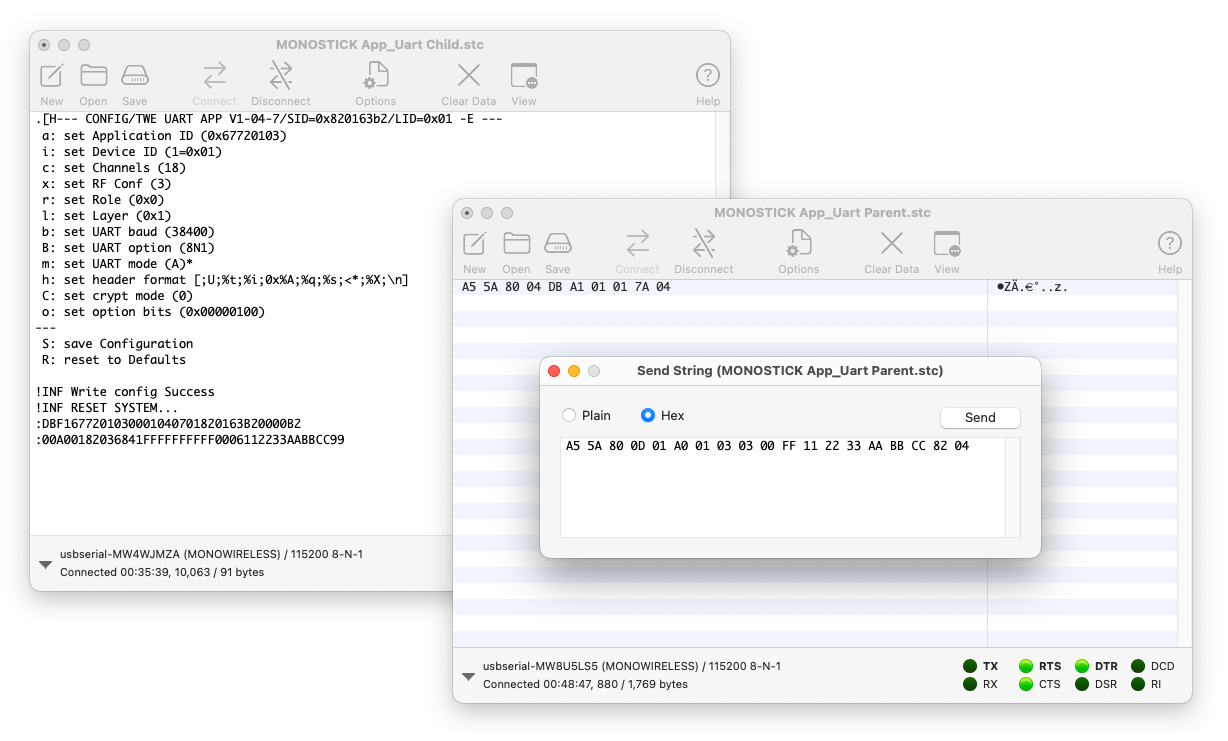
The following figure shows an example of sending the byte sequence 0x11 0x22 0x33 0xAA 0xBB 0xCC several times from the Parent to all Children using the simplified format.
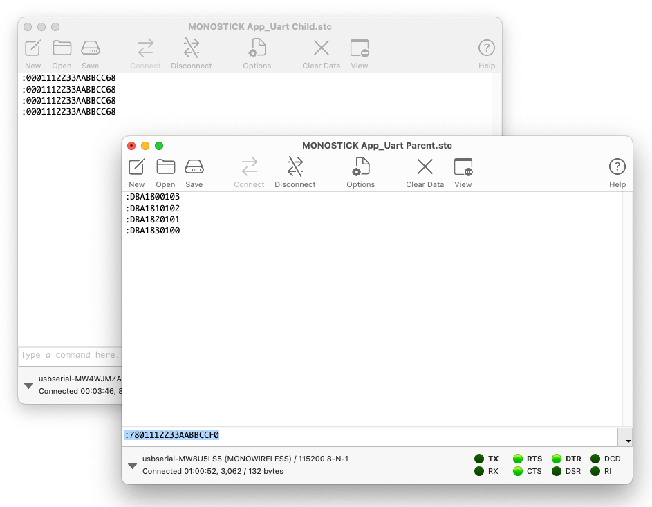
Example of using ASCII format mode
For the format of the serial communication app’s ASCII format mode, please refer to the manual.
Serial Communication App Format Mode (Binary)
In the serial communication app’s binary format mode, set Options > Terminal > Terminal Mode to Raw Mode and uncheck Options > Transmit > Send String Options > Terminate 'Send String' Data.
To display received data in hexadecimal, select View > View Hex.
To send data represented in hexadecimal, select Connection > Send String... to open the send screen, and choose the Hex radio button.
The following figure shows an example of sending the byte sequence 0x11 0x22 0x33 0xAA 0xBB 0xCC from the Parent to all Children using the simplified format.
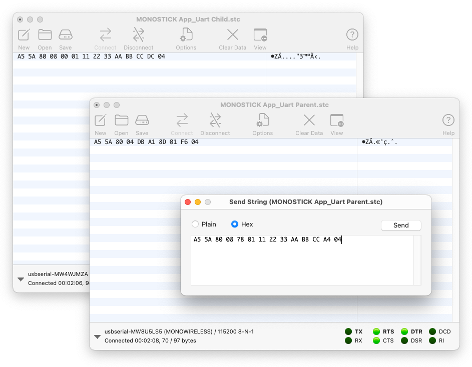
Example of using binary format mode
For the format of the serial communication app’s binary format mode, please refer to the manual.
2.2 - Using Interactive Mode Programmatically
How to access interactive mode programmatically
Since the interactive mode uses the serial port, it can also be operated programmatically.
In production processes, there may be situations where you want to use interactive mode automatically. Here, we introduce an example of reading and writing configuration values using Python.
Mechanism of Interactive Mode
In its initial state, the RX port of TWELITE operates at 115200bps 8N1. To transition into interactive mode, input + three times at intervals of approximately 200 to 1000ms, or for some applications, pull the SET pin low during startup. Since interactive mode accepts only ASCII characters as input, it can be freely controlled programmatically.
Implementation Example
Reading Configuration Values Using Python for Serial Communication App
Below is a script that reads the serial ID and configuration values from a TWELITE device programmed with the serial communication app App_Uart, via TWELITE R2/R3.
The tweliter module is used to identify TWELITE R2/R3, retrieve the serial port, and control the reset pin of TWELITE R2/R3.
pip install tweliter
Script
Using Python 3.12.
For the serial communication app specifications, we enter interactive mode by inputting + three times here.
# -*- coding: utf-8 -*-

import time
import re

from tweliter import Tweliter  # Mono Wireless module for TWELITE R devices


def get_serial_id_and_settings() -> tuple[str, dict[str, str]] | None:
    """
    Get the serial ID and settings from the interactive mode of a TWELITE R device.

    Returns:
        tuple[str, dict[str, str]] | None:
            A tuple containing:
            - str: the serial ID (e.g., "0x82010079")
            - dict[str, str]: the settings dictionary (e.g., {'a': '0x67720103', ...})
            Returns None if the device cannot be accessed or the output is invalid.

    Notes:
        Example output from the interactive mode of an App_Uart device:
        --- CONFIG/TWE UART APP V1-04-6/SID=0x82010079/LID=0x78 -- ---
         a: set Application ID (0x67720103)
         i: set Device ID (120=0x78)
         c: set Channels (18)
         x: set RF Conf (3)
         r: set Role (0x0)
         l: set Layer (0x1)
         b: set UART baud (38400)
         B: set UART option (8N1)
         m: set UART mode (E)
         k: set Tx Trigger (sep=0x0d0a, min_bytes=0 dly=0[ms])
         h: set header format [;U;%t;%i;0x%A;%q;%s;<*;%X;\n]
         C: set crypt mode (0)
         o: set option bits (0x00000100)
        ---
         S: save Configuration
         R: reset to Defaults
    """
    try:
        with Tweliter(
            type_filter=Tweliter.Type.TWELITE_R2 | Tweliter.Type.TWELITE_R3
        ) as liter:
            # Reset the device
            liter.reset_device()

            # Get the serial port instance (pyserial)
            ser = liter.get_serial_instance()
            ser.timeout = 1.0

            # Enter to the interactive mode
            for _ in range(3):
                ser.write("+")
                time.sleep(0.3)

            # Read the output
            raw_output = ser.read_until(b"S:").decode("utf-8")

            # Reset the device (Exit interactive mode)
            liter.reset_device()
    except IOError as e:
        print(f"Couldn't open the device {e}")
        return None

    # Find the settings block in the output
    filter_output = re.search(r"---(.*?)---(.*?)---", raw_output, re.DOTALL)
    if filter_output:
        information_line = filter_output.group(1)
        settings_block = filter_output.group(2)
    else:
        print("No settings block found.")
        return None

    # Extract serial id from the information line
    serial_id_match = re.search(r"SID=0x([0-9A-Fa-f]+)", information_line)
    if serial_id_match:
        serial_id = f"0x{serial_id_match.group(1)}"
    else:
        print("Serial ID not found.")
        return None

    # Extract key-value pairs (str,str) from the settings block
    settings_dict = dict(
        re.findall(r"^\s*(\w):.*?\(([^()]*)\)", settings_block, re.MULTILINE)
    )

    return serial_id, settings_dict


def main() -> None:
    # Get the serial ID and settings from the device
    result = get_serial_id_and_settings()
    if result is None:
        print("Failed to retrieve serial ID and settings.")
        return
    serial_id, settings = result

    # Show the results
    print(f"Serial ID: {serial_id}")
    for id, value in settings.items():
        match id:
            case "a":
                print(f"Application ID: {value}")
            # case "i":
            #     print(f"Logical ID: {value}")
            # case "c":
            #     print(f"Channel: {value}")


if __name__ == "__main__":
    main()
Explanation
Flow of Reading Output from Interactive Mode
- Reset the TWELITE
- Resetting brings the device back to its initial state for entering interactive mode. This reset is performed by controlling the reset pin on TWELITE R2/R3.
- Obtain the serial port instance
- Using
pyserial, obtain an instance for accessing serial I/O of TWELITE from the PC. Through this instance, you can send commands and read data.
- Using
- Input
+three times- By sending
+three times at fixed intervals (200–1000ms), TWELITE transitions into interactive mode. This method is the same as manual operation by the user.
- By sending
- Read output up to the line starting with
S:- In interactive mode, the line
S:appears after a series of configuration items. Reading up to this point ensures that all configuration contents are retrieved.
- In interactive mode, the line
- Reset the TWELITE
- After reading, reset again to return from interactive mode to normal operation.
with Tweliter(
    type_filter=Tweliter.Type.TWELITE_R2 | Tweliter.Type.TWELITE_R3
) as liter:
    # Reset the device
    liter.reset_device()

    # Get the serial port instance (pyserial)
    ser = liter.get_serial_instance()
    ser.timeout = 1.0

    # Enter to the interactive mode
    for _ in range(3):
        ser.write("+")
        time.sleep(0.3)

    # Read the output
    raw_output = ser.read_until(b"S:").decode("utf-8")

    # Reset the device (Exit interactive mode)
    liter.reset_device()
Flow of Interpreting Output from Interactive Mode
- Extract the line and the block enclosed by
---- Use
re.search(r"---(.*?)---(.*?)---", raw_output, re.DOTALL)to retrieve the full configuration info from the interactive mode output, divided into two parts:information_line(containing serial ID etc.), andsettings_block(listing configuration items).re.DOTALLenables matching across multiple lines.
- Use
- Extract the serial ID from the first line
- Use
re.search(r"SID=0x([0-9A-Fa-f]+)", information_line)to obtain the hexadecimal ID followingSID=0x, format it as a string like0x82010079. Both uppercase and lowercase hex digits are matched.
- Use
- Extract command ID and value pairs from the block
- Use
re.findall(r"^\s*(\w):.*?\(([^()]*)\)", settings_block, re.MULTILINE)to extract lines in the format likea: ... (value), retrieving the one-letter command ID and the value inside parentheses. Leading spaces and any characters after the colon are ignored.re.MULTILINEenables matching across multiple lines.
- Use
# Find the settings block in the output
filter_output = re.search(r"---(.*?)---(.*?)---", raw_output, re.DOTALL)
if filter_output:
    information_line = filter_output.group(1)
    settings_block = filter_output.group(2)
else:
    print("No settings block found.")
    return None

# Extract serial id from the information line
serial_id_match = re.search(r"SID=0x([0-9A-Fa-f]+)", information_line)
if serial_id_match:
    serial_id = f"0x{serial_id_match.group(1)}"
else:
    print("Serial ID not found.")
    return None

# Extract key-value pairs (str,str) from the settings block
settings_dict = dict(
    re.findall(r"^\s*(\w):.*?\(([^()]*)\)", settings_block, re.MULTILINE)
)

return serial_id, settings_dict
Reading Configuration Values and Changing Logical Device ID Using Python for Cue App
Here, we introduce a script that reads the serial ID and configuration values from a TWELITE device programmed with the Cue app App_Cue, via TWELITE R2/R3, and updates the logical device ID.
The tweliter module is used to identify TWELITE R2/R3, retrieve the serial port, and control the reset pin of TWELITE R2/R3.
pip install tweliter
Script
Using Python 3.12.
For the Cue app specifications, we enter interactive mode by pulling the SET pin low here.
Easy! Standard apps and serial communication apps may not support SET pin transition
Input + three times at 200-1000ms intervals as follows:
def enter_interactive_mode_manually(liter: Tweliter) -> None:
    liter.reset_device()
    ser = liter.get_serial_instance()
    for _ in range(3):
        ser.write("+")
        time.sleep(0.3)
# -*- coding: utf-8 -*-

import time
import re

from tweliter import Tweliter  # Mono Wireless module for TWELITE R devices


def revert_all_setttings(liter: Tweliter) -> None:
    """
    Revert all settings

    Args:
        liter (Tweliter): Tweliter instance
    """
    # Get the serial port instance (pyserial)
    ser = liter.get_serial_instance()
    ser.timeout = 1.0

    # Set logical id
    ser.write("R")
    time.sleep(0.3)
    ser.write("S")


def get_serial_id_and_settings(liter: Tweliter) -> tuple[str, dict[str, str]] | None:
    """
    Get the serial ID and all settings

    Args:
        liter (Tweliter): Tweliter instance

    Returns:
        tuple[str, dict[str, str]] | None:
            A tuple containing:
            - str: the serial ID (e.g., "82010079")
            - dict[str, str]: the settings dictionary (e.g., {'a': '0x67720103', ...})
            Returns None if the device cannot be accessed or the output is invalid.
    """
    # Get the serial port instance (pyserial)
    ser = liter.get_serial_instance()
    ser.timeout = 1.0

    # Read the output
    raw_output = ser.read_until(b"S:").decode("utf-8")

    # Find the settings block in the output
    filter_output = re.search(r"---(.*?)---(.*?)---", raw_output, re.DOTALL)
    if filter_output:
        information_line = filter_output.group(1)
        settings_block = filter_output.group(2)
    else:
        print("No settings block found.")
        return None

    # Extract serial id from the information line
    serial_id_match = re.search(r"SID=0x([0-9A-Fa-f]+)", information_line)
    if serial_id_match:
        serial_id = f"0x{serial_id_match.group(1)}"
    else:
        print("Serial ID not found.")
        return None

    # Extract key-value pairs (str,str) from the settings block
    settings_dict = dict(
        re.findall(r"^\s*(\w):.*?\(([^()]*)\)", settings_block, re.MULTILINE)
    )

    return serial_id, settings_dict


def set_logical_id(liter: Tweliter, lid: int) -> None:
    """
    Set new logical id and save it

    Args:
        liter (Tweliter): Tweliter instance
        lid (int): New logical id
    """
    # Get the serial port instance (pyserial)
    ser = liter.get_serial_instance()
    ser.timeout = 1.0

    # Set logical id
    ser.write("i")
    time.sleep(0.3)
    ser.write(f"{lid}\r\n")
    time.sleep(0.3)
    ser.write("S")


def print_settings(settings: dict[str, str], select: list[str] | None = None) -> None:
    """
    Print settings

    Args:
        settings (dict[str, str]): Settings dict
        select (list[str] | None): List of IDs for selected entries. None to select all
    """
    for id, value in settings.items():
        if select is None or id in select:
            match id:
                case "a":
                    print(f"Application ID: {value}")
                case "i":
                    print(f"Logical ID: {value}")
                case "c":
                    print(f"Channel: {value}")
                case "x":
                    print(f"Power / Retry: {value}")
                case "b":
                    print(f"UART Baudrate: {value}")
                case "B":
                    print(f"UART Options: {value}")
                case "k":
                    print(f"Encryption Key: {value}")
                case "o":
                    print(f"Option Bits: {value}")
                case "t":
                    print(f"Transmission Interval: {value}")
                case "p":
                    print(f"Sensor Parameters: {value}")
                case _:
                    print(f"{id}: {value}")


def main() -> None:
    """
    Main function
    """
    lid_to_set = 25
    try:
        with Tweliter(
            type_filter=Tweliter.Type.TWELITE_R2 | Tweliter.Type.TWELITE_R3
        ) as liter:
            # Revert all settings
            print("\nReverting to default settings...")
            liter.enter_interactive_mode()
            revert_all_setttings(liter)

            # Get the serial ID and settings from the device
            liter.enter_interactive_mode()
            result = get_serial_id_and_settings(liter)
            if result is None:
                print("Failed to get serial ID and settings.")
                return
            serial_id, settings = result
            print(f"\nCurrent settings for the device {serial_id}:")
            print_settings(settings)

            # Set logical ID
            print(
                f"\nModifying Logical ID {settings["i"]} to {lid_to_set}=0x{lid_to_set:02x}..."
            )
            set_logical_id(liter, lid_to_set)

            # Get updated setttings
            liter.enter_interactive_mode()
            result = get_serial_id_and_settings(liter)
            if result is None:
                print("Failed to get serial ID and settings.")
                return
            serial_id, settings = result
            print(f"\nUpdated setting(s) for the device {serial_id}:")
            print_settings(settings, select=["i"])

            # Reset the device (Exit interactive mode)
            liter.reset_device()

    except IOError as e:
        print(f"Couldn't open the device {e}")
        return None


if __name__ == "__main__":
    main()
When you run the script, it changes the logical device ID to 25 as shown in the following example:
python modify_app_cue_settings.py
Using TWE-Lite-R R27BESFJ @ ftdi://::R27BESFJ/1

Reverting to default settings...

Current settings for the device 0x8201872b:
Application ID: 0x67720102
Logical ID: --
Channel: 18
Power / Retry: 13
UART Baudrate: 38400
UART Options: 8N1
Encryption Key: 0xA5A5A5A5
Option Bits: 0x00000001
Transmission Interval: 5
Sensor Parameters: 0x00000000

Modifying Logical ID -- to 25=0x19...

Updated setting(s) for the device 0x8201872b:
Logical ID: 25=0x19
Explanation
Process for Reading Configuration Values
- Get the serial port instance
- Use
get_serial_instance()to obtain the serial port instance.
- Use
- Read the string from the serial port up to
S:which contains the save command description- In interactive mode, after the configuration values are displayed, the save command description
S:appears. By reading up to this point, you can retrieve all configuration content.
- In interactive mode, after the configuration values are displayed, the save command description
- Extract the first line and the block enclosed by
---- Use
re.search(r"---(.*?)---(.*?)---", raw_output, re.DOTALL)to extract the interactive mode output into two parts: the first capture group is the information line (information_line) containing the serial ID, and the next group is the settings block (settings_block) containing the configuration items.re.DOTALLenables full-text search including newlines.
- Use
- Extract the serial ID from the first line
- Use
re.search(r"SID=0x([0-9A-Fa-f]+)", information_line)to retrieve the hexadecimal ID value followingSID=0x(e.g.,82010079) and format it as a string like0x82010079. Hexadecimal digits are extracted regardless of case.
- Use
- Extract command ID and value pairs from the block
- Use
re.findall(r"^\s*(\w):.*?\(([^()]*)\)", settings_block, re.MULTILINE)to extract the command ID (single character) and the value within parentheses from lines in the formata: ... (value). Leading spaces and any characters after the colon are skipped, extracting only the first parenthesized value found.re.MULTILINEenables matching across multiple lines.
- Use
    # Get the serial port instance (pyserial)
    ser = liter.get_serial_instance()
    ser.timeout = 1.0

    # Read the output
    raw_output = ser.read_until(b"S:").decode("utf-8")

    # Find the settings block in the output
    filter_output = re.search(r"---(.*?)---(.*?)---", raw_output, re.DOTALL)
    if filter_output:
        information_line = filter_output.group(1)
        settings_block = filter_output.group(2)
    else:
        print("No settings block found.")
        return None

    # Extract serial id from the information line
    serial_id_match = re.search(r"SID=0x([0-9A-Fa-f]+)", information_line)
    if serial_id_match:
        serial_id = f"0x{serial_id_match.group(1)}"
    else:
        print("Serial ID not found.")
        return None

    # Extract key-value pairs (str,str) from the settings block
    settings_dict = dict(
        re.findall(r"^\s*(\w):.*?\(([^()]*)\)", settings_block, re.MULTILINE)
    )

    return serial_id, settings_dict
3 - Hardware Development
Various information related to TWELITE hardware development.
3.1 - On Power Saving Performance
How to operate TWELITE on batteries for long periods
To achieve low power consumption as a wireless microcontroller module for connecting things, it is necessary to suppress the current consumption of each process, but it is also very important to shorten the startup time and processing time. Even if the current consumption is low, low power consumption cannot be achieved if the processing time is long.
Power Consumption (Current)
The following are typical current consumptions when sending one packet of 30 bytes.
- Standard output BLUE
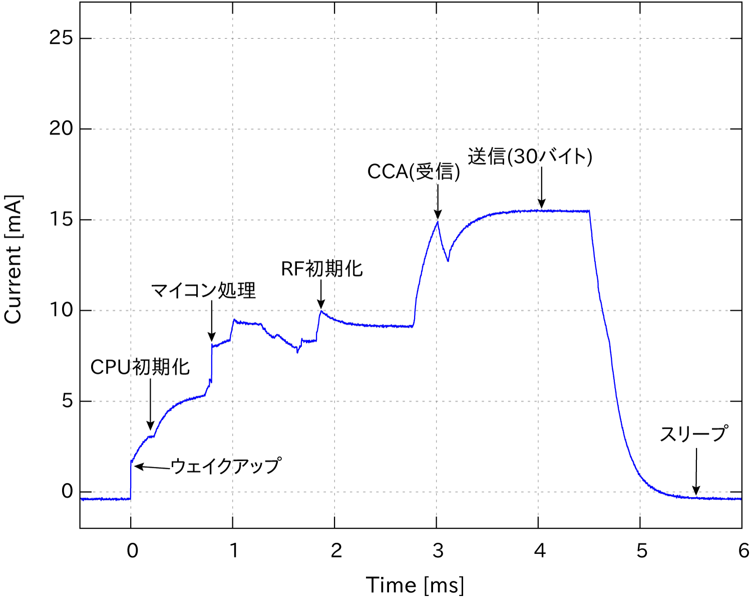
In the case of TWELITE BLUE
- High output RED
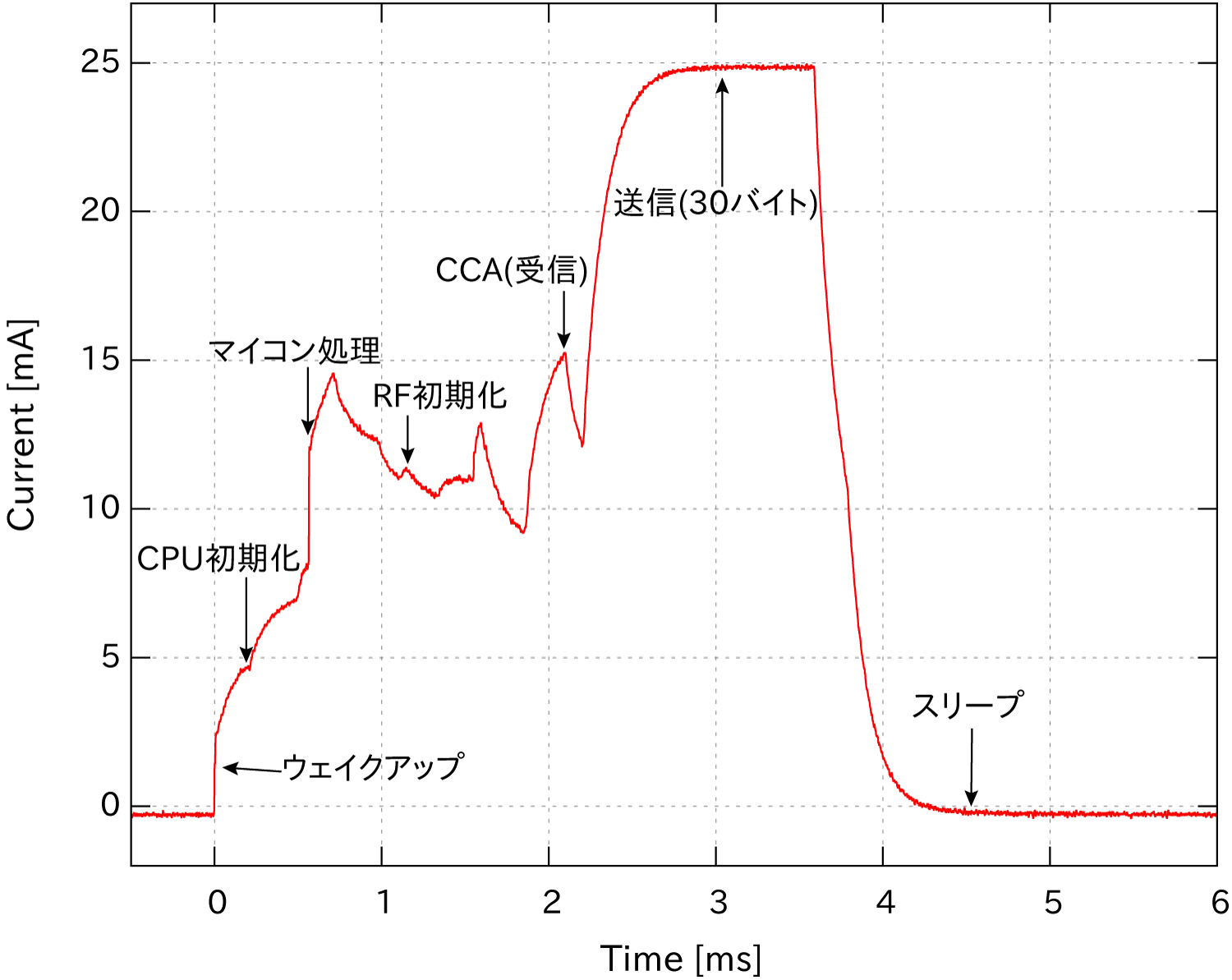
In the case of TWELITE RED
High output RED has a higher current consumption during transmission compared to standard output BLUE, but since the processing time is shorter, the current consumption for sending one packet is equivalent.
TWELITE achieves power saving through low current consumption, instant startup, and high-speed processing.
The current consumption during reception is BLUE
17.0mA and RED 14.7mA. If continuous reception is required, constant power supply or a battery with large capacity is necessary.Please also consider the power consumption of peripheral circuits such as sensors during development.
The pre-installed Extremely Simple! Standard App at shipment is not designed for power saving. If you want to pursue power saving, please modify the app.
Examples of Power Consumption
Here is an example of a wireless tag with minimized power consumption of TWELITE. In this example, no sensors are used, and 4 bytes of ID data are periodically sent using the built-in timer. No reception acknowledgment (ACK) from the transmission counterpart is performed. The average current consumption when sending one packet is 11.6mA, and the processing time is 2.5ms.
- Average current consumption considering only the awake time
11.6[mA] * (2.5/1000)[ms] = 29[uA]
- Average current consumption including sleep (RAM on) time
29[uA] + 1.5[uA] = 30.5[uA] = 0.0305[mA]
Assuming transmission once every second and a CR2032 battery capacity of 220mAh,
220/( 0.0305 ) = approximately 7213[hours] = 300[days] = 10 months
The graph below shows the battery life when using a coin-type battery (CR2032). The battery life exceeds 10 years when data is sent every 30 seconds.
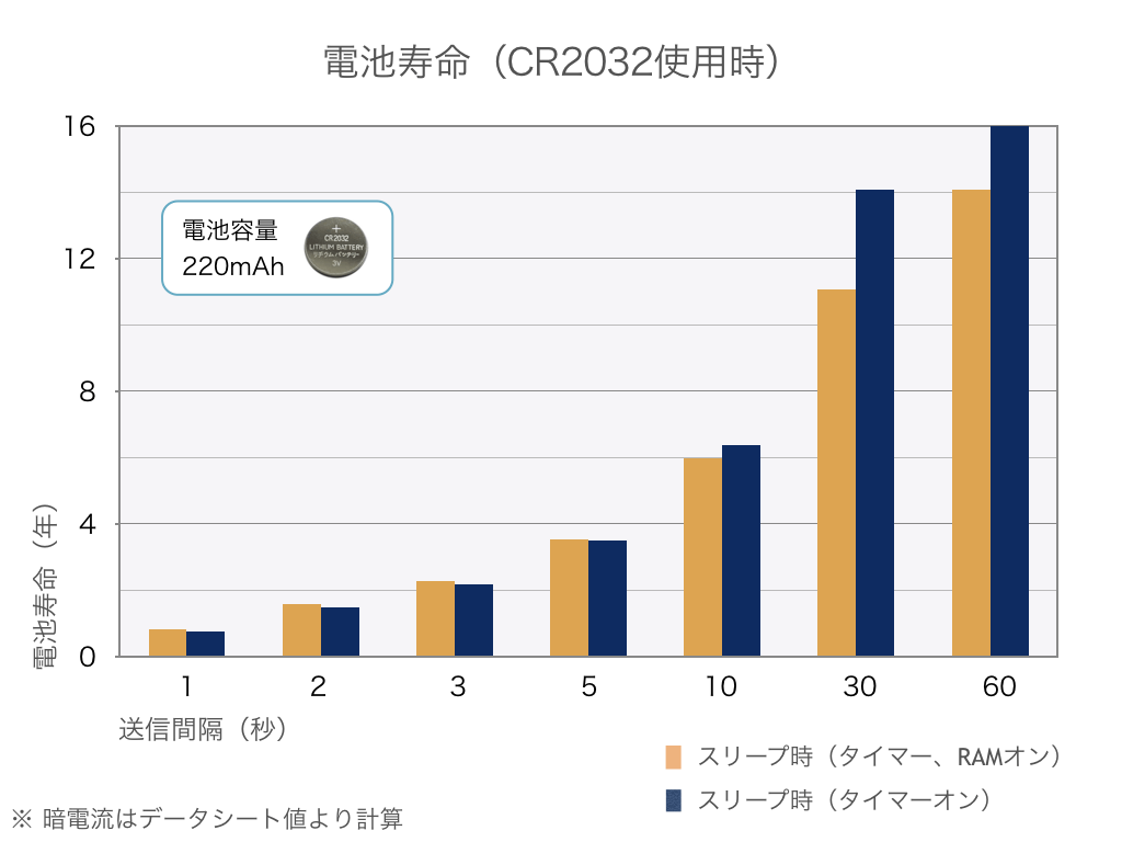
If sending intervals are less than 5 seconds, it is better to keep RAM on and sleep to extend battery life.
The values obtained by this calculation are approximate and may vary depending on battery performance and operating temperature.
Due to the current supply capability of coin batteries (please refer to the battery manufacturer’s datasheet for details), continuous operation of the wireless module is not possible. When using coin batteries, please perform intermittent operation including sleep. More information
The battery life introduced here is a reference value and may be longer or shorter in reality. Battery life varies depending on its performance and operating conditions. (Pulse load [generally extends life], instantaneous overload current [reduces life], temperature conditions [life decreases at high temperature, voltage drops at low temperature]) Please check the characteristics of the battery you are using in detail. Please be especially careful about voltage drops in batteries with high internal resistance.
3.1.1 - Battery Operation and Buffer Capacitor
A buffer capacitor is used when operating TWELITE with a small-capacity battery
When using a small-capacity battery, it may not be able to supply sufficient current. For example, the rated current of a CR2032 is about 0.2mA, and even at maximum, only around 2~3mA is expected.
For instance, when TWELITE transmits a wireless packet, it momentarily consumes about 20mA. At this time, insufficient current supply and voltage drop may occur, causing the system to malfunction.
To avoid this, a buffer capacitor is connected between VCC and GND. (Additionally, it is necessary to control startup using a reset IC.)
Assuming the power is cut off, with a voltage of 3.3V and an average current of 10mA, a 100uF buffer capacitor can keep the system running for about 10ms. From the moment the power is cut off, current is supplied from the buffer capacitor, and the wireless module will operate until the voltage drops near 2V, where the wireless module becomes inoperable.
This is an effective measure for intermittent operation and transmission. A caution is that if retransmissions occur, the time until transmission completion significantly increases. Since one retransmission consumes several milliseconds, a buffer capacitor considering the number of retransmissions is necessary.
However, in cases where the device waits for reception, it continuously consumes a large current (17.2mA), so dealing with this using the above buffer method is difficult. Please use a battery with a higher supply capacity.
Approximate Capacitor Capacity and Operating Time
The current consumption of TWELITE series modules does not depend on the supply voltage. Because the current is constant, we calculate how long the module can operate based on the capacitor’s charge.
If a capacitor with capacitance C stores charge corresponding to voltage v, the time t for the voltage to drop from v to 0 at a constant current i is t = Cv/i.
The time required for the voltage to drop from 3.3V to 2.1V at current i is C(3.3-2.1)/i. For i=10mA and C=100uF, this calculates to 12ms. According to this calculation, if the power to a module operating at 3.3V is suddenly cut, and the average current is 10mA, the operation time can be extended by about 12ms.
The current value of
10mAis only an assumed average. Please refer to actual measured consumption current values.
3.2 - Antenna Implementation
About certification compliance for customer-designed RF circuits and antennas
This document describes important points regarding certification compliance for customer-designed wireless circuits and antennas.
- When certification is obtained by our company and design information is provided to the customer
- Please perform design and production according to the technical information submitted by our company at the time of certification.
- Our certified business partner has been provided with technical information about the RF circuits and antennas. We will present the customer with essential requirements for certification and comments related to performance based on this technical information.
- There may be differences of opinion between the certified business partner and other views. In the unlikely event that problems arise due to these differing opinions, our company and the certified business partner will provide information based on the technical information at the time of certification, but the following actions will not be taken:
- Conducting negotiations or equivalent actions.
- Compensation arising from these issues.
- For overseas certification, please verify compliance status by yourself.
- Requirements for overseas certification may be updated. Please refer to the latest information at that time.
- We cannot provide a final opinion on the appropriateness of your design and implementation.
- When the customer designs independently
- In most cases, certification is required for independent designs.
- To facilitate smooth handling of technical documents related to certification, we generally guide you to our designated business partners. Please contact us for details.
3.2.1 - Implementation of Inverted-F Antenna
Notes on implementing an inverted-F antenna
This document describes important notes regarding the radio certification of the inverted-F pattern antenna (TWELITE-SMD-ANT-REVF).
The reference design is published at the following link.
monowireless/PCB_REF_DESIGN_KICAD: Reference Schematic/PCB design data for KiCAD
Requirements
The following conditions must be satisfied.
- Wiring must be done according to the pattern and through-holes as per the design data.
- Do not modify areas marked as no-change (DO NOT WIRE) in the design data.
- The specified printed circuit board must be used.
- Please specify a 1mm thickness to the PCB manufacturer.
- (If a thickness other than 1mm is required, please refer to the notes below.)
- Due to dielectric properties, glass epoxy (FR-4) must be specified. Other materials are not allowed.
- Layer structure must be double-sided or 4-layer.
- There are no specific requirements for solder mask color or silkscreen.
- Confirm that manufacturing and assembly are performed as per the design.
- There should be no design deviations exceeding commonly accepted tolerances.
- The wireless module must be properly mounted.
Design and Performance
GND Area
The inverted-F antenna consists of an inverted-F shaped element and a GND pattern directly beneath the module. The area of the GND pattern significantly affects performance. The optimal size is between 20x20 mm and 40x40 mm.
Wiring
The inverted-F antenna is sensitive to external wiring. For example, wireless tags such as TWELITE CUE that place a coin cell holder on the GND surface without external wiring can achieve near-ideal performance.
If some wiring must be routed on the GND surface, keep it to a minimum. For example, having just one wire passing through generally has negligible impact.
Performance Evaluation
We offer a paid service to measure wireless performance (gain, etc.) on customer-designed boards.
Especially for inverted-F pattern antennas, performance may fall below expectations depending on the parent board and wiring conditions. Measuring allows you to verify whether the design roughly meets expected values.
If your policy requires strict performance evaluation such as maximum gain, please conduct measurements at official sites (e.g., authorized testing facilities) that provide certified results.
Certification Status
Japan
Applicable Modules
- TWE-L-WX
- MW-R-WX
Requirements
Must satisfy the above requirements.
North America (FCC)
Please ensure compliance yourself regarding overseas certifications.
Applicable Modules
- TWE-L-WX
Requirements
- Must satisfy the above requirements.
- Other requirements such as labeling should follow FCC rules.
Europe (EU)
Please ensure compliance yourself regarding overseas certifications.
Applicable Modules
- TWE-L-WX
Requirements
- Must satisfy the above requirements.
- Other requirements such as labeling should follow CE rules.
Other Regions
No certification support.
About PCB Thickness
This design specifies an FR-4 1mm thick PCB. This thickness is the basis for radio certification approval, so using a different thickness will result in loss of certification.
However, for Japan domestic certification only, the following PCB thicknesses are also approved:
- t=0.5mm (Not approved for overseas certifications obtained by us)
- t=0.8mm (Not approved for overseas certifications obtained by us)
- t=1.6mm (Not approved for overseas certifications obtained by us)
Since the antenna pattern is optimized for t=1mm, characteristics will slightly change. However, the change is usually very minor. Characteristic patterns on PCBs sized according to the ideal GND size show changes of about 1 to 3 dB.
3.2.2 - Implementation of SMA Connector
Notes on implementing an SMA connector
This document provides important notes regarding the radio certification of the SMA connector (TWELITE-SMD-SMA-CONN).
The reference design is published at the following location.
monowireless/PCB_REF_DESIGN_KICAD: Reference Schematic/PCB design data for KiCAD
Requirements
Common
- Wire according to the pattern and through-holes as specified in the design data
- Do not modify areas marked as “No wiring, DO NOT WIRE” in the design data
- Use the specified printed circuit board
- Specify a thickness of 1mm to the PCB manufacturer
- Due to dielectric constant considerations, use glass epoxy (FR-4); other materials are not allowed
- Layer structure should be double-sided or 4-layer
- There are no specific requirements for solder resist color or silk screen
- Confirm that manufacturing and assembly are according to the design
- Ensure no design deviations exceed commonly cited tolerances
- Confirm that the wireless module is properly mounted
- Use the specified connector
Specified Connector
TOCONNE SMA-LR4 (Au)
COSMTEC RESOURCES S-037-TGG
https://akizukidenshi.com/catalog/g/gC-02569/
Available at Akizuki Denshi Tsusho
Certification Status
Japan
Target Modules
- TWE-L-WX
- MW-R-WX
Requirements
- Must satisfy the above requirements
North America (FCC)
No certification support.
Europe (EU)
No certification support.
Other Regions
No certification support.
3.2.3 - Implementation of Wire Antenna
Notes on implementing a wire antenna
You can create an antenna using a wire with a diameter of φ=0.8mm or less.
It can be bent arbitrarily for use, but performance may significantly decrease compared to when it is upright. To maintain antenna performance, please refer to “Wire Antenna Bending Patterns.” (Keep dimensional differences within 0.5mm.)