超簡単!標準アプリのデータを取得・操作
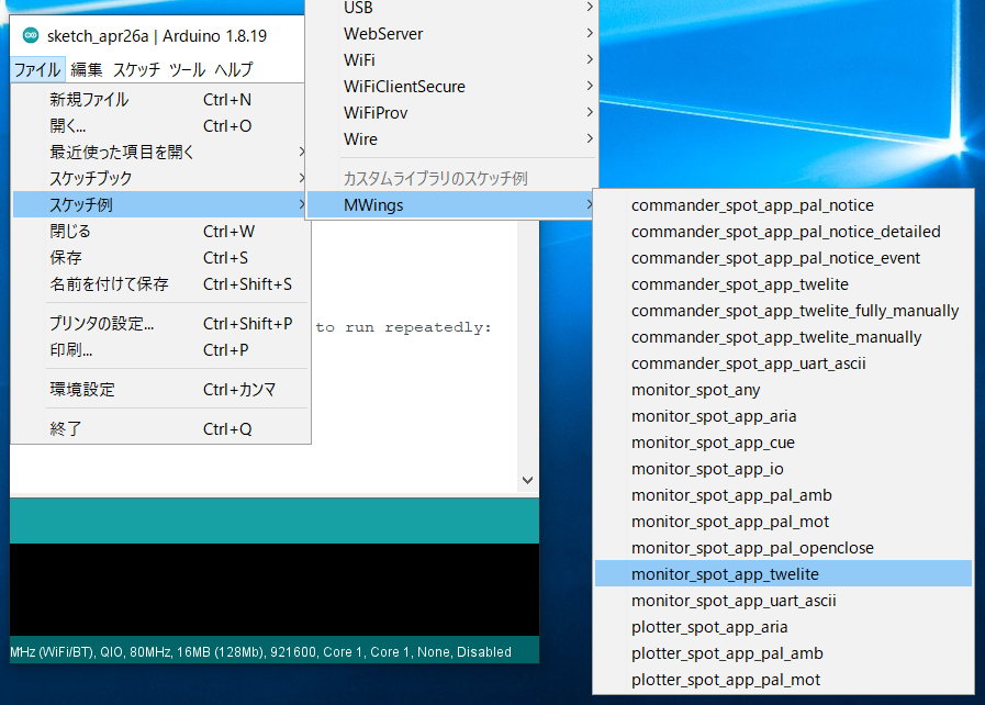
monitor_spot_app_twelite の解説です。最後に、相手先の出力ポートを操作する改変を行います。サンプルスケッチの保存場所
MWings ライブラリを導入していれば、Arduino IDE の ファイル -> スケッチ例 -> MWings -> monitor_spot_app_twelite からスケッチを開くことができます。

保存場所
スケッチ
以下はソースコード本体です。
// Monitor example for TWELITE SPOT: Receive data from App_Twelite

#include <Arduino.h>
#include "MWings.h"

const int RST_PIN = 5;
const int PRG_PIN = 4;
const int LED_PIN = 18;

const uint8_t TWE_CHANNEL = 18;
const uint32_t TWE_APP_ID = 0x67720102;

void setup()
{
    // Initialize serial ports
    Serial.begin(115200);
    Serial.println("Monitor example for TWELITE SPOT: App_Twelite");
    Serial2.begin(115200, SERIAL_8N1);

    // Initialize TWELITE
    Twelite.begin(Serial2,
                  LED_PIN, RST_PIN, PRG_PIN,
                  TWE_CHANNEL, TWE_APP_ID);

    // Attach an event handler to process packets from App_Twelite
    Twelite.on([](const ParsedAppTwelitePacket& packet) {
        Serial.println("");
        Serial.print("Packet Timestamp:  ");
        Serial.print(packet.u16SequenceNumber / 64.0f, 1); Serial.println(" sec");
        Serial.print("Source Logical ID: 0x");
        Serial.println(packet.u8SourceLogicalId, HEX);
        Serial.print("LQI:               ");
        Serial.println(packet.u8Lqi, DEC);
        Serial.print("Supply Voltage:    ");
        Serial.print(packet.u16SupplyVoltage, DEC); Serial.println(" mV");
        Serial.print("Digital Input:    ");
        Serial.print(packet.bDiState[0] ? " DI1:Lo" : " DI1:Hi");
        Serial.print(packet.bDiState[1] ? " DI2:Lo" : " DI2:Hi");
        Serial.print(packet.bDiState[2] ? " DI3:Lo" : " DI3:Hi");
        Serial.println(packet.bDiState[3] ? " DI4:Lo" : " DI4:Hi");
        Serial.print("Analog Input:     ");
        Serial.print(" AI1:"); Serial.print(packet.u16AiVoltage[0]); Serial.print(" mV");
        Serial.print(" AI2:"); Serial.print(packet.u16AiVoltage[1]); Serial.print(" mV");
        Serial.print(" AI3:"); Serial.print(packet.u16AiVoltage[2]); Serial.print(" mV");
        Serial.print(" AI4:"); Serial.print(packet.u16AiVoltage[3]); Serial.println(" mV");
    });
}

void loop()
{
    // Update TWELITE
    Twelite.update();
}
ライブラリのインクルード
4行目では、MWings ライブラリをインクルードしています。
#include "MWings.h"
ピン番号の定義
6-8行目では、ピン番号を定義しています。
const int RST_PIN = 5;
const int PRG_PIN = 4;
const int LED_PIN = 18;
| 名称 | 内容 |
|---|---|
RST_PIN | TWELITE の RST ピンが接続されているピンの番号 |
PRG_PIN | TWELITE の PRG ピンが接続されているピンの番号 |
LED_PIN | 基板上の ESP32 用 LED が接続されているピンの番号 |
TWELITE 設定の定義
10-11行目では、TWELITE SPOT に搭載された TWELITE 親機に適用する設定を定義しています。
const uint8_t TWE_CHANNEL = 18;
const uint32_t TWE_APP_ID = 0x67720102;
| 名称 | 内容 |
|---|---|
TWE_CHANNEL | TWELITE の 周波数チャネル |
TWE_APP_ID | TWELITE の アプリケーション ID |
シリアルポートの設定
16-18行目では、使用するシリアルポートを初期化するとともに、シリアルモニタへ起動メッセージを出力しています。
    Serial.begin(115200);
    Serial.println("Monitor example for TWELITE SPOT: App_Twelite");
    Serial2.begin(115200, SERIAL_8N1);
Serial は、Arduino IDE の シリアルモニタとの通信に使います。シリアルモニタの設定に合わせて、ボーレートを 115200 bps としています。
一方、Serial2 は、TWELITE SPOT に搭載された TWELITE 親機との通信に使います。こちらも TWELITE 親機の初期設定に合わせて、ボーレートを 115200 bps としています。
TWELITE の設定
21-23行目では、Twelite.begin() を呼び出し、TWELITE SPOT に搭載された TWELITE 親機の設定と起動を行っています。
    Twelite.begin(Serial2,
                      LED_PIN, RST_PIN, PRG_PIN,
                      TWE_CHANNEL, TWE_APP_ID);
パケット受信時のイベントの登録
26-46行目では、Twelite.on() を呼び出し、送られたデータに対して行う処理を登録しています。
ここでは、受信したパケットの内容をシリアルモニタに出力しています。
    Twelite.on([](const ParsedAppTwelitePacket& packet) {
        Serial.println("");
        Serial.print("Packet Timestamp:  ");
        Serial.print(packet.u16SequenceNumber / 64.0f, 1); Serial.println(" sec");
        Serial.print("Source Logical ID: 0x");
        Serial.println(packet.u8SourceLogicalId, HEX);
        Serial.print("LQI:               ");
        Serial.println(packet.u8Lqi, DEC);
        Serial.print("Supply Voltage:    ");
        Serial.print(packet.u16SupplyVoltage, DEC); Serial.println(" mV");
        Serial.print("Digital Input:    ");
        Serial.print(packet.bDiState[0] ? " DI1:Lo" : " DI1:Hi");
        Serial.print(packet.bDiState[1] ? " DI2:Lo" : " DI2:Hi");
        Serial.print(packet.bDiState[2] ? " DI3:Lo" : " DI3:Hi");
        Serial.println(packet.bDiState[3] ? " DI4:Lo" : " DI4:Hi");
        Serial.print("Analog Input:     ");
        Serial.print(" AI1:"); Serial.print(packet.u16AiVoltage[0]); Serial.print(" mV");
        Serial.print(" AI2:"); Serial.print(packet.u16AiVoltage[1]); Serial.print(" mV");
        Serial.print(" AI3:"); Serial.print(packet.u16AiVoltage[2]); Serial.print(" mV");
        Serial.print(" AI4:"); Serial.print(packet.u16AiVoltage[3]); Serial.println(" mV");
    });
上記のイベントは、超簡単!標準アプリからのパケットを受信したときにだけ呼び出されます。
受信したパケットの内容は ParsedAppTwelitePacket 型の引数 packet に格納されています。
メッセージの内容
| メッセージ | 内容 |
|---|---|
Packet Timestamp | パケットのタイムスタンプ |
Source Logical ID | 送信元 TWELITE の論理デバイスID |
LQI | 無線通信品質(0~255) |
Supply Voltage | 電源電圧 (mV) |
Digital Input | デジタル入力の状態 |
Analog Input | アナログ入力の状態 |
TWELITE のデータの更新
52行目では、Twelite.update() を呼び出しています。
Twelite.update();
相手先の出力ポートの操作
超簡単!標準アプリの入力ポートの状態を取得するだけでなく、超簡単!標準アプリの出力ポートを操作してみましょう。
ここでは、TWELITE SPOT が受信した際の LQI(無線通信品質)に基づき、相手端末が TWELITE SPOT に近づいた際に、相手端末のデジタル出力ポートを点灯させてみます。
スケッチの改変
改変内容
はじめに、13行目へ下記のコードを追加します。
AppTweliteCommand command;
上記のコードでは、送信するコマンドの内容を格納する AppTweliteCommand を作成しています。
次に、49-51行目へ下記のコードを追加します。
        command.u8DestinationLogicalId = packet.u8SourceLogicalId; // LID
        command.bDiState[0] = (packet.u8Lqi >= 100) ? true : false; // DI1
        Twelite.send(command);
上記のコードでは、AppTweliteCommand を操作し、Twelite.send() でコマンドを送信しています。
ここでは、送信先の論理デバイス ID を設定し、出力ポート(DO1)の状態を指定しています。
データの詳細は AppTweliteCommand のリファレンス をご覧ください。
これでスケッチの改変は終了です。改変後のコードを示します。
// Monitor example for TWELITE SPOT: Receive data from and send data to App_Twelite

#include <Arduino.h>
#include "MWings.h"

const int RST_PIN = 5;
const int PRG_PIN = 4;
const int LED_PIN = 18;

const uint8_t TWE_CHANNEL = 18;
const uint32_t TWE_APP_ID = 0x67720102;

AppTweliteCommand command;

void setup()
{
    // Initialize serial ports
    Serial.begin(115200);
    Serial.println("Monitor example for TWELITE SPOT: App_Twelite");
    Serial2.begin(115200, SERIAL_8N1);

    // Initialize TWELITE
    Twelite.begin(Serial2,
                  LED_PIN, RST_PIN, PRG_PIN,
                  TWE_CHANNEL, TWE_APP_ID);

    // Attach an event handler to process packets from App_Twelite
    Twelite.on([](const ParsedAppTwelitePacket& packet) {
        Serial.println("");
        Serial.print("Packet Timestamp:  ");
        Serial.print(packet.u16SequenceNumber / 64.0f, 1); Serial.println(" sec");
        Serial.print("Source Logical ID: 0x");
        Serial.println(packet.u8SourceLogicalId, HEX);
        Serial.print("LQI:               ");
        Serial.println(packet.u8Lqi, DEC);
        Serial.print("Supply Voltage:    ");
        Serial.print(packet.u16SupplyVoltage, DEC); Serial.println(" mV");
        Serial.print("Digital Input:    ");
        Serial.print(packet.bDiState[0] ? " DI1:Lo" : " DI1:Hi");
        Serial.print(packet.bDiState[1] ? " DI2:Lo" : " DI2:Hi");
        Serial.print(packet.bDiState[2] ? " DI3:Lo" : " DI3:Hi");
        Serial.println(packet.bDiState[3] ? " DI4:Lo" : " DI4:Hi");
        Serial.print("Analog Input:     ");
        Serial.print(" AI1:"); Serial.print(packet.u16AiVoltage[0]); Serial.print(" mV");
        Serial.print(" AI2:"); Serial.print(packet.u16AiVoltage[1]); Serial.print(" mV");
        Serial.print(" AI3:"); Serial.print(packet.u16AiVoltage[2]); Serial.print(" mV");
        Serial.print(" AI4:"); Serial.print(packet.u16AiVoltage[3]); Serial.println(" mV");

        command.u8DestinationLogicalId = packet.u8SourceLogicalId; // LID
        command.bDiState[0] = (packet.u8Lqi >= 100) ? true : false; // DI1
        Twelite.send(command);
    });
}

void loop()
{
    // Update TWELITE
    Twelite.update();
}
動作確認
子機の TWELITE DIP の DO1 ピンと VCC ピンの間に LED と電流制限抵抗を接続してください。
改変したスケッチを書き込むと、TWELITE DIP が TWELITE SPOT に近づいた際(=通信品質がよいとき)に LED が点灯します。